1
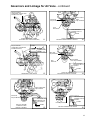
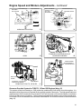
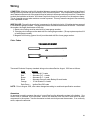
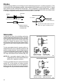
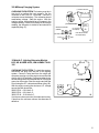
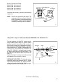
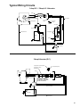
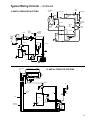
16 Amp Alternator System with External Regulator
CHECKING THE SYSTEM: An open circuit D.C.
voltage check cannot be made with this system. If
a known good battery fails to maintain a charge,
proceed in making an A.C. voltage test.
D.C. OUTPUT - RED
SOLENOID
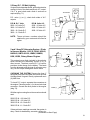
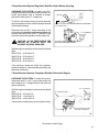
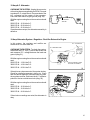
Disconnect the red D.C. output connector at the
wire harness and connect the probes from an A.C.
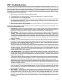
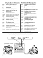
voltmeter to the wire terminals at the regulatorrectifier (diag. 93).
SWITCH
GREEN
MAGNETO
GROUND
FUSE
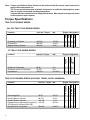
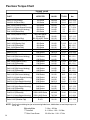
With the engine running the minimum values should
read:
2500 R.P.M. - 21 Volts A.C.
3000 R.P.M. - 26.5 Volts A.C.
3600 R.P.M. - 31.0 Volts A.C.
LIGHT
BATTERY
AMMETER
REGULATED
D.C. OUTPUT
YELLOW
If the minimum values are noted, the alternator is
operating properly. If less than the above values are
noted, the alternator is defective.
RED
NOTE: D.C. OUTPUT MUST BE DISCONNECTED TO PERFORM
A.C. OUTPUT TEST.
93
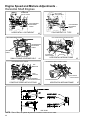
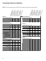
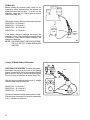
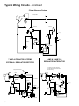
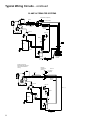
20 Amp Alternator System
In this system, the regulator and rectifier are
combined in one solid state unit which is mounted
into the blower housing of the engine.
CHECKING THE SYSTEM: An open circuit D.C.
voltage check cannot be made. If a known good
battery fails to maintain a charge, proceed to make
an A.C. voltage test.
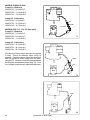
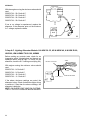
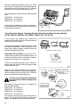
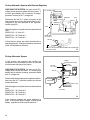
Disconnect the plug leading to the regulator rectifier,
and insert the A.C. voltmeter probes into the two
outside terminals.
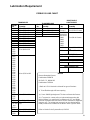
With the engine running the minimum values should
read:
2500 R.P.M. - 32.0 Volts A.C.
3000 R.P.M. - 38.0 Volts A.C.
3600 R.P.M. - 45.0 Volts A.C.
GREEN
(MAGNETO SHUT-OFF)
YELLOW
(A.C. LEAD)
YELLOW
(A.C. LEAD)
YELLOW
A.C.
YELLOW
GREEN
RED
RECT./REG.
GREEN
(MAGNETO SHUT-OFF)
RED
(D.C. WIRE)
94
If the minimum readings are noted, alternator is
okay. If the system fails to charge a known good
battery, regulator-rectifier must be defective.
48