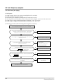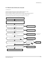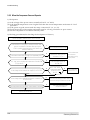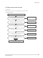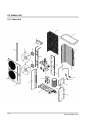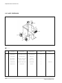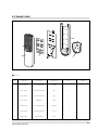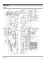
1
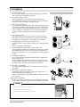
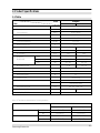
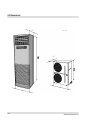
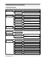
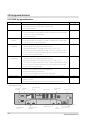
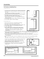
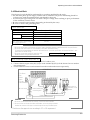
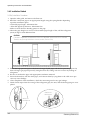
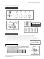
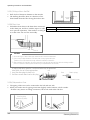
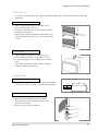
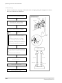
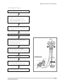
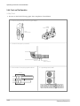
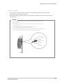
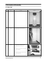
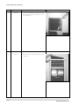
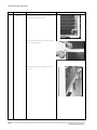
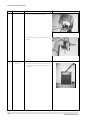
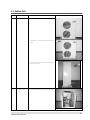
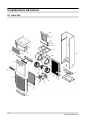
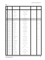
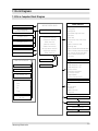
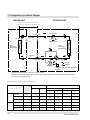
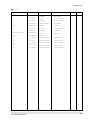
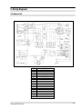
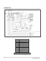
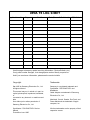
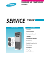
PACKAGED AIR CONDITIONER
APH450PG
SERVICE
Manual
AIR CONDITIONER
CONTENTS
1. Precautions
2. Product Specifications
3. Operating Instructions and
Installation
4. Disassembly and Reassembly
5. Troubleshooting
6. Exploded Views and Parts List
7. Block Diagrams
8. PCB Diagrams
9. Wiring Diagrams
10. Schematic Diagrams
© Samsung Electronics Co., Ltd. MAY. 1998.
Printed in Korea.
Code No. DB81-10147A(1)
1. Precautions
1) Turn off the the power.
Be sure to turn off the power before attempting to repair the
unit such as the disassembly of the unit.
Turn off the sub power switch separately installed.
2) Be careful of electric shock
When checking the circuit with the power connected in
unavoidable circumstances, take special care not to touch the
live parts. There is a danger of electric shock.
3) Use of appropriate parts
Be sure to use the genuine parts of the relevant model when it
is necessary to replace parts. (Replace parts instead of repairing with regard to the malfunctioning of electric contact areas.
Never attempt to modify the unit. It is extremely dangerous
for the consumer to attempt to repair the unit on his(her)
own.)
4) Use of proper tools
Use appropriate tools for repair, and use measuring equipment after accurate calibration. Using worn tools may result
in problems, including poor contact and poor connection.
5) Avoid damage to electric wire or electric cord.
Check the electric cord or electric wire for any damage during
repair.
Be sure to replace it if damaged.
6) Avoid intermediate connection of the electric cord.
Never attempt to make an intermediate connection by cutting
the middle area of the electric cord or make a connection to
the power receptacle as it is very dangerous, causing problems
or fire.
No connection with the power receptacle
7) Checking of insulation
Be sure to check the insulation resistance after completion of
the assembly work.
(Check whether the insulation resistance of the electric wire
and grounding terminal is over 30MΩ by using the insulation
resistance tester, and then connect the power source.)
8) Checking of grounding
Check the grounding condition, and perform repair if poorly
grounded.
9) Checking of installation condition
Check the installation condition of the unit, and perform
repair if there is any defective area.
If the unit remains in an unstable installing condition, install it
at a new site.
10) Be careful of children
As the repair of the unit involves a lot of dangerous elements,
do not allow children to approach nearby during repair work.
Cleaning
Upon completion of the repair, clean the air
conditioner and surrounding area, and
inform the customer of completion of the repair.
Samsung Electronics
1-1
MEMO
1-2
Samsung Electronics
2. Product Specifications
2-1 Table
Model
ITEM
APH450PG
Indoor unit
Outdoor unit
Power source
ø/V/Hz
3 / 380 / 50
Capacity
kcal/h
11,250 / 12,200
(Cooling/Heating)
BTU/h
45,000 / 48,800
Aux. heater
Watt/h
3,000
W
5,000 / 4,700
E.E.R (Cooling/Heating)
kcal/Wh
2.25 / 2.60
Running current (C/H)
A
9 / 8.7
Power consumption
Noise level (C/H)
dBA
53 / 54
63
Moisture removal
l/hr
5.8
Air circulation
3
m /h
1,920
4,800
Dimension
Width
mm
590 / 704
930 / 1,200
(Net/Packed)
Height
mm
1,810 / 1,925
1,240 / 1,370
Depth
mm
420 / 600
385 / 540
75 / 85
123 / 133
Weight(Net/Packed)
kg
Piping box
14
R-22
Refrigerant type
kg
Refrigerant quantity
4.8
Compressor type
Reciprocating
Protective device
Internal thermostat (CM)
High pressure switch
Refrigerant piping size
inch
Drain piping size
mm
Loading Q’ty (20’/40’)
set
Gas : 3/4”, Liquid : 3/8”
I.D 18
I.D 16
12 / 24
Note: (1) The data are measured at the following conditions.
APH450PG
Indoor air temperature
Outdoor air temperature
Samsung Electronics
Cooling
Heating
DB
27.0˚C(80.6˚F)
20.0˚C(68.0˚F)
WB
19.0˚C(66.2˚F)
12.0˚C(53.6˚F)
DB
35.0˚C(95.0˚F)
7.0˚C(44.6˚F)
WB
24.0˚C(75.2˚F)
6.0˚C(42.8˚F)
2-1
2-2 Dimensions
Unit : mm
420
385
930
590
2-2
Samsung Electronics
3. Operating instructions and Installation
3-1 Operating Instructions
Operation
Main switch operation
Operation of remote
controller
Function selection
Fan speed
selector mode
Control of fan motor step according to current temperature
Auto heat mode
Control of fan motor step according to current temperature
Cool mode
Control of cool according to the difference between current
and desired temperature
Heat mode
Control of cool according to the difference between current
and desired temperature
Fan mode
Operation of indoor fan motor only
Manual 3-step
Airflow selector
mode
Left-right turn
Convenience function
Turbo operation
Convenience reservation
Function selector
High, medium, low
Control of fan motor step according to current temperature
Turbo-operating compressor and powerful operating fan
motor(30minutes)
Reserve function which is off after on time of 1, 2, 3, 4, or 5
hours
Auto cool, auto heat, cool, heat, turbo, fan lamp
Selection of fan speed
Low, medium, high lamp
Selection of airflow
Left-right lamp
Current temperature
Indoor temperature display
Desired temperature
Desired temperature display
Fan speed diagram
Low, medium, high, turbo lamp
Convenience reservation
Current time
Samsung Electronics
Operation of turbo, cool, heat, fan
Auto cool mode
Auto
LED display
function
Operation of auto cool, auto heat, cool, heat, fan
Reserve lamp and reserve time display
Current time display
3-1
3-2 Key type and functions
3-2-1 PANEL key type and functions
Key name
On/off
Mode selection
Fan speed
selection
Temperature(time)
setting(up)
Temperature(time)
setting(down)
Change of display
Brief reservation
Heater on/off selection
Key operating function
Start and end of operation
- ON 1 time = operation start, ON again = operation end.
- No continued operation
Change of the operation mode
- Each time the button is pressed(ON), the mode is changed in the following order:
“auto → cool → fan”(standard=auto)
- No continued operation
Setting of the indoor fan motor speed
- Each time the button is pressed ON, the mode is changed in the following order:
“low → medium → high”(standard=high)
Increase the desired temperature(current time)
- Temperature: When pressing the button(ON) one time,
the desired temperature is increased by the unit of 1°C.(18°C- 30°C)
- Time: When pressing the button(ON) one time, the time is increased by 1 minte.
If the “on” button is pressed continuously, the time is increased by 10 minutes.
- One short, and continued operation
Decrease the desired temperature (current time)
- Temperature: When pressing the button(ON) one time,
the desired temperature is decreased by the unit of 1°C. (18°C - 30°C)
- Time: When pressing the button(ON) one time, the time is decreased by 1 minute.
If the “on” button is pressed continuously, the time is decreased by 10 minutes.
- One short, and continued operation
The temperature and current time can be changed.
- If the “on” key is pressed 1 time, current temperature
and desired temperature are displayed.
- If the “on” key is pressed 1 time, current time is displayed.
The hours of 1,2,3,4 and 5 is selected whenever one time of on is performed.
If the switch is selected to the on direction, the heater is operating at the heater
operation condition.
The heater is not operating when the switch is selected to the off position.
Key type
TACT
TACT
TACT
TACT
TACT
TACT
TACT
SLIDE
* Operating functions
Fan Speed
adjustment
Fan Speed
display
Time/Temperature
display
Operating Light
Remote control
Sensor
Power Light
Operating
Mode Selection
Time/Temperature
Selection
3-2
Time or Temperature
adjustment
On/Off Button
Timer
adjustment
Auxiliary Heater
Switch (option)
Samsung Electronics
3-3 Accessory Parts List
3-3-1 Connection Parts
No.
Part Name
3-3-2 Others
Q’ty
Remarks
No.
Connecting pipe
Q’ty
Remarks
Leg holder for indoor unit
1
3/8”
(ø9.52mm)
4
1
1
Piping box
Screw
Connecting pipe
2
Part Name
3/4”
(ø19.05mm)
4
TH M4 X 25
4
2
1
Cable clamp
Heater cable (3 strand)
1
3
TH M4 X 12
Option
(Piping box)
Protection tube
3
12N
8N
6N
Indoor unit fixing holder
4
2
3
1
Option(Piping box)
1
1
4
Leg holder for outdoor unit
5
Connecting wire (7 strand)
4
1
5
Insulation rubber bottom
6
Wire of sensor (2 strand)
1
6
4
Cable tie
7
5
Power cable
1
7
Piping box
Putty
8
3
Drain hose
1
8
Pipe band
9
Finishing tape
Rubber cabi slot
2
9
3
Piping box
10
Insulation tape
1
10
11
Insulation tube for indoor
unit piping connection
Samsung Electronics
1
Rubber cabi hole
11
1
Drain plug out
1
12
1
3-3
3-4 Installation
3-4-1 Selection of Installation Place
3-4-1(a) Indoor Unit
• Install the unit at a place close to the wall facing the outside
as it is necessary to perform piping connection with the outdoor unit.
- It is effective to install the unit at a window side to ensure
uniform distribution of indoor temperature.
• Install the unit at a place where there is no obstacle against
the wind around the air inlet and air outlet.
• Install the unit horizontally at a stable, rigid place.
(When installing the unit at a place subjected to vibration,
noise may occur.)
• Avoid a place near the door which is frequented by people.
• Avoid a place subject to direct sunlight.
Top view
Above 50cm
Side view
Above 20cm
3-4-1(b) Outdoor Unit
•
•
•
•
•
•
Place free from the risk of combustible gas leakage.
Place which can bear the weight of the unit.
Place which can bear the fixing strength of the outdoor unit.
Avoid a place subject to oil (including machine oil).
Avoid a saline place.
Avoid a place subject to sulfide gas (hot spring zone).
(When installing the unit at such special environmental
conditions, it may cause machine trouble. When it is
Above 100cm
unavoidable to use such places. It requires special
maintenance.)
• A place where the discharge air and noise of the outdoor unit do not disturb the neighborhood.
(Take special care not to cause any inconvenience to your neighbors when installing the unit on
the borderline with your neighborhood.)
• A place where strong wind does not head against the air outlet of the outdoor unit.
(If a strong wind heads directly against the air outlet at the time of cool operation, a safety device
can be operated.)
• Do not install the outdoor unit at an unstable place such as outer wall of an apartment or building.
The outdoor unit may fall down, causing severe personal or property damage or loss.
* If there is any unavoidable reason to install the unit at such
a place, take the following measures against the wind;
1. When installing the unit at a roadside concentrated with
buildings, install it parallel with the road.
2. Install the unit so that the air outlet faces toward the wall
at a place such as rooftop, which may be subjected to
strong wind.
Strong wind
Wall
Roof top
* The outdoor unit should be installed in accordance with the service space.
Above 15cm
Above 50cm
Space for piping
and wiring
Above 50cm
Above 15cm
Above 15cm
The air inlet faces toward the wall.
3-4
Above 30cm
Space for piping
and wiring
The air outlet faces toward the wall.
Samsung Electronics
Operating instructions and Installation
3-4-2 Electrical Work
The electrical work should be performed by a specialist qualified for the work.
• Use the three phase power supply, and be sure to install the sub power distributing board for
exclusive use with the unit(separately purchased by the user).
* Avoid octopus-type wiring as it can cause a drop in voltage, thus resulting in poor performance
of the automatic control circuit.
• Be sure to install circuit breaker (separately purchased by the user).
• Be sure to connect the grounding wire.
Electric power spec
Power
Ampere of breaker
Knife switch
Switch
3phase 4wires 380V
50 A
25 A
25 A
2.5 mm2
Fuse
Size of grounding wire
Min. size of electric wires from/to
the indoor/outdoor unit
0.75 mm 2
CAUTION
• Be sure to use the wires, and switches or fuses of power distribution board are qualified and fulfill the specification.
• Be sure to install knife switch or circuit breaker on the power distribution board.
• The electrical and grounding work should be performed as per “ technical specification of electrical facilities ” and “
specification of internal wiring ”.
• Be sure to connect main electrical input wires with
342V ~ 418V
Applicable voltage 380V
bolted connectors using compressed terminal.
When connecting 3Phase 4wires 380V AC
1. Remove cover of electric box on side panel of outdoor unit.
2. Connect electric input wires (R,S,T,N) to each terminal (R,S,T,N) of the electric box on outdoor
unit respectively.
3. Connect electric wires to each terminal on indoor and outdoor unit respectively.
OUTDOOR SIDE
1:Thin Brown
2:Sky
3:Brown
4:Black
5:Thin sky
6:Dark Black
Wire of sensor
Knife switch or
automatic circuit
breaker
Indoor/outdoor unit
connecting wire
Inoor
unit
Power cable
Heater cable
CAUTION
• Be sure to connect electrical wires correctly, if not it can cause a trouble.
* Be sure to fix wires from/to the indoor and outdoor unit on the piping insulated.
Avoid wires contact to bare pipe or valve directly without any insulated spacer.
* Must be use the approval wire according to IEC or EN requirement.
Samsung Electronics
3-5
Operating instructions and Installation
3-4-3 Installation Method
3-4-3(a) Installation Procedures
1. Open the inlet grille, and remove the flare nut.
2. Bend the connection pipe to an appropriate length using the spring bender depending
upon the installation place.
- Allowable pipe length : Maximum 25m
- Allowable pipe drop distance : Maximum 15m
- Make no more than ten bending points on the pipe
• When the pipe length is in excess of the standard pipe length of 5m, add the refrigerant
(R-22) of 50g for each additional 1m.
CAUTION
• If the pipe is lengthened, the performance of the unit is degraded, and the service life is shortened.
Therefore, the pipe length should be as short as possible (less then 15m).
Outdoor
unit
Indoor
unit
Indoor
unit
Outdoor
unit
3. Install the high pressure pipe to the heat exchanger liquid pipe, and the low pressure pipe to the
heat exchanger gas pipe respectively using the flare nut, taking care not to cause any leakage of
refrigerant.
4. Be sure to insulate the pipe with appropriate insulation material.
5. Insert the drain hose into the drain pipe, and connect them by tying them to the cable tie to prevent any water leakage.
6. After completion of the installation, check the connecting area for any gas leakage.
7. Wind a finish tape when the wiring of the refrigerant pipe, the unit, and the drain piping are completed.
Outdoor unit
checking area
Indoor unit
checking area
3-6
Samsung Electronics
Operating instructions and Installation
3-4-3(b) Connection of Refrigerant Piping
Flare Processing
1. Cut the pipe using the pipe cutter.
Oblique
Roughness
Burr
2. Insert the flare nut into the pipe, and then perform the flare processing.
Outer Diameter
ø 9.52mm
ø 19.05 mm
A ( out / in)
1.7 / 1.0 (mm)
2.2 / 1.5 (mm)
• Unproper flaring
Inclined
Surface
damaged
Cracked
Uneven
thickness
Pipe Bending
1. Perform bending of the pipe using the bender which has a specified bending radius.
2. Be sure to take full care to perform bending of the pipe successfully at one time.
Bending and unbending the pipe more than twice makes the bending work increasingly difficult.
3. You may use the spring inserted into the gas pipe instead of the bender to bend the pipe.
4. When you bend the pipe using the spring, hold the pipe with both hands to prevent any distortion, and secure a minimum bending radius of more than 100mm.
Spring
Tightening of Connection Parts
•
Align the center of the connection piping, and tighten the flare nut
by turning it with hand. Then tighten it again using the spanner in
the direction as shown in the figure.
Outer Diameter
ø 9.52mm
ø 19.05mm
Tightening Torque
400 kg • cm
700kg • cm
Samsung Electronics
Final Torque
450 kg • cm
750kg • cm
Remarks
3-7
Operating instructions and Installation
3-4-3(c) Drilling a Hole in the Wall
•
•
Drill a hole of 70mm in diameter to the outside.
The drilling should be done at a distance of less
than 150mm from the floor facing the indoor unit.
ø70mm
Less than
150mm
3-4-3(d) Drain Hose
•
Extend the drain hose to the drain hose connected
to the drain pan, and fix it with the tape or a cable
tie to prevent separation. Then make a covering of
it so that water can not flow outwardly.
Drain pan
Piping Material Vinyl Chloride(Outer diameter ø 16mm)
Insulator
Foamed Polyethylene
Insulation
Band
Drain hose
Indoor and
outdoor
connection
CAUTION
1. As the draining is of natural drain type, make the drain hose direct downward.
2. If there is any foreign substance in the drain plate, it may clog the drain pipe.
Therefore, be sure to remove the foreign substance inside after installation.
3. After completion of installation, be sure to pour water into the drain pan, and then check the draining condition.
(There is no problem in draining when the draining is completed within 20 seconds.)
• In heating and deice operation, condensed water may be generated.
Install drain line as following procedure.
Hole
1. Insert the drain plug into base hole.
2. And then connect drain hose to drin plug.
Base
Drain plug
Drain hose
3-4-3(e) Rat-prevention Cover
•
•
The piping of this unit can be connected to the left and rear side.
When you hit the area for piping connection slightly with a hammer, a hole is made.
- If there is any reason to change connection, fill in hole with ruber cabi slot.
Holes for piping
connection (2 points)
3-8
Samsung Electronics
Operating instructions and Installation
3-4-3(f) Indoor Unit
In order to install drain hose through wall, adjust height (max. 150mm) of the indoor unit using
leg holder.
Fixing to the floor
•
When using the leg holder of the indoor unit.
1. Lie down the unit on flat floor.
2. Insert the leg holders into screwed holes and then
fasten them clockwise.
3. Turn the unit right and adjust horizontal line of it.
* Mis-alignment of the unit can cause vibration and
noise.
Leg holder of
the indoor unit
Fixing to the wall
•
When using fixing holder of the indoor unit.
1. Fix the holder using long screw bolts on wall.
2. Fix the unit using two screw bolts or four anchor
bolts.
(Size of the screw hole on the holder is ø4.5mm
and size of the bolt is ø6mm.)
Fixing holder of the
indoor unit
3-4-3(g) Outdoor Unit
When using the anchor bolt
1. Fix the unit on a flat, rigid floor using the anchor bolt.
(Anchor bolt : M10 x 4 points - separately purchased)
Anchor bolt fixing dimensions
A
B
Unit:mm
840
415
When using the leg holder of the outdoor unit
1. Insert the foot holder (4EA).
2. Remove the nut fastened to the leg holder,
and then insert the leg holder into the hole of
the outdoor unit leg.
3. Fix the unit securely with the nut.
Nut
Outdoor unit leg
Leg holder
Foot holder
Samsung Electronics
3-9
Operating instructions and Installation
3-4-3(h) Air Purge
•
Be sure to perform the air purge of the indoor unit, and piping using the refrigerant of the outdoor unit at the time of installation.
Open the cap of the valve(B), and valve(A).
OUTDOOR UNIT
Gas side
Open the valve cock of the valve(B) by
approximately 45°. After an elapse
of 10 seconds, close the valve cork.
Liquid side
Check the connection piping for leakage.
Not
Ieaking
Leaking
• Close the nut for the connection piping
again.
Proceed to h when there is no leakage.
• If it is necessary to perform repair due to
continuous leakage of gas, discharge the
refrigerant gas, and repair the leaking area.
Then revacuum and refill the refrigerant.
Flare nut
Valve cock
Cap
Needle valve cap
Indoor unit
* Open the needle cap of the valve(A), and press
the needle valve for 3 seconds to drain the gas
out.
Repeat this procedure three times.
Open the valve cock of valve(B) and
valve(A) completely.a
Liquid side
Gas side
3-Way valve
3-Way valve
Close the cap of each valve.
Outdoor unit
Check the valve for leakage.
3-10
Samsung Electronics
Operating instructions and Installation
3-4-3(i) Refrigerant Charging
Air purge(at the time of new installation only)
Close the gas pipe side valve by turning it
clockwise.
Connect the pressure gauge to the low
pressure side service valve, and then open
the gas pipe side valve again.
Connect it to the refrigerant filling tank.
(Turn the tank upside down : Fill the refrigerant
in liquid form.)
Start cooling operation.
Check the pressure of the pressure gauge.
Check whether the low pressure side is within
the range of 4.5~5.5kg/cm2G
(outside temperature 35°C).
Open the tank and refill the refrigerant
until arriving at the proper pressure.
(Refill the refrigent slowly checking the pressure.)
Stop operation.
OUTDOOR UNIT
Gas pipe side
Close the gas pipe side valve, and loosen
the pressure gauge connected.
Then open the gas pipe side valve again.
Liquid
pipe side
Tighten the cap of each valve using
a specified tool.
Samsung Electronics
3-11
Operating instructions and Installation
3-4-4 Check and Test Operation
3-4-4(a) Check
•
Be sure to check the following again after completion of installation.
1. Check the piping connection area for any gas leakage.
Outdoor
connection area
Indoor
connection area
2. Is the drain hose properly connected?
Drain hose
3. Is the insulation of the piping in good condition?
Indoor and
outdoor connection
4. Is grounding properly made?
Insulation
3-12
Samsung Electronics
Operating instructions and Installation
3-4-4(b) Test Operation
•
After checking, read the owner’s instructions carefully, and perform a test operation.
Then deliver the unit to the customer.
(When delivering the unit, be sure to read carefully and follow the contents of the owner ’s
instructions.)
CAUTION
1. Be sure to check whether the service valve is opened before attempting to perform
the test operation.
2. Never attempt to start test operation by force pressing the electronic contactor as
it is very dangerous.
(This is very dangerous as the protective device does not work.)
3. Be sure to perform the test operation after installation.
It is easy to start the test operation in winter if you increase the sensor temperature to
23°C ~ 25°C by holding the indoor temperature sensor. (Cooling operation)
Temperature Sensor
Samsung Electronics
3-13
MEMO
3-14
Samsung Electronics
4. Disassembly and Reassembly
4-1 Indoor Unit
No
Parts
Procedure
1
Indoor unit
2
Inlet grille
1) Open the inlet grille and remove the
connection ring.
3
Main PCB
1) Separate the PCB connect wire after
separating the control box cover.
Remarks
2) Separate the connection wire to separate the
front cover and duct.
3) The main PCB should be separated by turn
over the mountain tab.
Samsung Electronics
4-1
Disassembly and reassembly
No
Parts
Procedure
4
Front cabi
1) The front cabi should be separated by giving
strength downward after loosening 2 screws
at the lower end.
5
Plate top
1) The plate top should be separated by loosening screws.
4-2
Remarks
Samsung Electronics
Disassembly and reassembly
No
Parts
6
Ass’y grille out
Procedure
Remarks
1) First loosen screws at left and right sides of
grille out.
2) Then the ass’y grille out should be separated
by giving strength upward ( ↑).
7
Ass’y Blower in
1) First loosen the 4 screws at left and right
sides.
2) Then the ass’y duct should be separated by
lifting it.
Samsung Electronics
4-3
Disassembly and reassembly
No
Parts
8
Evaporator
Procedure
Remarks
1) First separate the cover after loosening the
screws fixed at evap cover R.
2) Then separate the 3 screws fixed at cabinet
BKT of evaporator BKT.
3) Evaporator should be separated by flinging
ahead.
4-4
Samsung Electronics
Disassembly and reassembly
No
Parts
Procedure
9
Motor
1) When the ass’y duct should be separated
from the motor, the 2 bracket should be separated first.
Remarks
2) Then the bolts fixed at the blower and motor
shaft should be separated.
3) Then the screws binding the holder top blower and duct should be separated.
4) The duct of one side should be separated as
the picture shows after loosening the upper
binder.
5) The binder of the motor and the duct should
be separated.
Samsung Electronics
4-5
Disassembly and reassembly
No
Parts
Procedure
Remarks
6) Then the motor should be separated.
7) The bracket fixed at the motor should be separated.
10
4-6
Panel PCB
1) Should be separated after loosening the insulating material and binders at the back of the
front side.
Samsung Electronics
4-2 Outdoor Unit
No
Parts
1
Outdoor unit
Procedure
Remarks
1) Packaged air conditioner outdoor unit
2) The binders of the front side should be separated.
3) The flank and the binders should be separated from each other.
2
Control box
Samsung Electronics
1) Connect distributed wires in the control box.
4-7
MEMO
4-8
Samsung Electronics
5. Troubleshooting
Troubleshooting
First,
Items to be checked first
Second,
Check the corrective actions in the case of occurrence of self-diagnosis mode
Third,
When the trouble is not related to the 1st or 2nd items above, check the troubled area in
detail in accordance with the fault analysis method by symptom.
5-1 Items to be checked first
1) Is the supply voltage appropriate?
The supply voltage: should be AC 187V-AC 253V/60Hz
2) Is the connecting wire between the indoor unit and outdoor unit appropriate?
Be sure to check whether the cables for the indoor unit and outdoor unit are securely connected
by the same terminal number.
3) When any claim occurs according to the contents of the table below, it is not related the trouble of
the air-conditioner at all.
No.
Operation of air-conditioner
Description
1
The compressor does not operate even though
the desired temperature is set lower than
room temperature (during the cooling operation)
The compressor operation is delayed for 3 minutes for the protection of
it during the restart of compressor. It operates normally after 3 minutes
delay even at the initial operation.
2
The hot wind does not come out even though the In order to prevent the discharging of cool wind, the room fan motor
desired temperature is set higher than the room operates only when the temperature of indoor heat exchanger is kept
temperature. (heating operation)
higher than a constant one.
3
The wind quantity is not controlled during the
automatic (cooling/heating) turbo operation.
The wind quantity is set by the micom during the automatic turbo
operation.
4
The temperature can not be set during the
automatic (cooling/heating) turbo blowing
operation.
The desired temperature is set automatically during the automatic
turbo operation. The wind blowing operation is simply the operation
mode for the circulation of indoor air.
5-2 Self-diagnosis and corrective actions
No.
Temperature
display
1
E1
Short of indoor temperature sensor
Open of Indoor temperature sensor
Check of departure of indoor temperature sensor
Check of PCB open/short
2
E5
Short of indoor heat exchanger sensor
Open of indoor heat exchanger sensor
3
E6
Short of outdoor heat exchanger sensor
Open of outdoor heat exchanger sensor
4
E7
5
EL
Short of heater temperature sensor
Open of heater temperature sensor
When the electrical heater is over heated
Check of indoor exchanger sensor departure
Check of PCB open/short
Replacement of sensor
Check of outdoor exchanger sensor departure
Check of PCB open/short
Replacement of sensor
Check of heater wiring diagram
Check of sensor attachment location
Check of heater temperature sensor departure
Check of PCB open/shore
Replacement of sensor
Samsung Electronics
Cause
Corrective actions
5-1
5-3 Fault Analysis by Symptom
5-3-1 No Power (No display)
1) Checkpoints
(1) Is the voltage of the power source normal?(AC 187V - AC 253V)
(2) Is the power line in good contact?
(3) Check the power fuse(F701, F702) and PCB fuse(F101) for open.
(4) Are the primary and secondary sides of the power-trans in good contact with the connector?
(5) Is the output voltage of REG1(KA7812) normal?(DC 11.5V - DC 12.5V)
(6) Is the output voltage of REG2(KA 7805) normal?(DC 4.5V - DC 5.5V)
2) Checking procedures(after checking the checkpoints of clause 1)
Turn off the power, and then turn it on in 5 seconds.
Is the room temperature displayed on the temperaturre
indicator, the display lamp turned on, and the panel
shutter down when pressing the on/off button.
Y
Then it is normal operation.
N
Is the voltage or the power trans AC 18V-21V secondary
side(CN11) normal?
N
Check and replace the power trans.
Y
Is the output voltage of REG1 and REG2 normal?
(REG1=12V, REG2=5V)
N
Y
Is the output wave at the MICOM(IC1) pin (No. 33~40) a
square wave?
Remove the shorted parts of the
power terminal.
Replace the defective parts.
(D101-104, REG1, REG2)
N
Check and replace the MICOM(IC1).
Y
Is the output wave at IC2 pin No. 11~18 a square wave?
N
Check and replace the IC2.
Y
Is the harness between the main PCB and panel PCB well
connected?
N
Reassemble or replace the harness
after checking it.
Y
LED display or panel PCB defective.
5-2
Samsung Electronics
Troubleshooting
5-3-2 When the Indoor Fan Motor does not Operate.
1) Checkpoints
(1) Is the voltage of the power source normal?(AC 187V-AC 253V)
(2) Is the indoor fan connector (CN71) in good contact?
(3) Is the starting condensor of the fan motor in good contact with the terminal?
(4) Is the resistance at both ends of the relay coil approximately 400Ω?
2) Checking procedures(after checking the checkpoints of clause 1)
Turn off the power, and then turn it on in 5 seconds.
Operate the on/off button, and operation mode key, and place
it in the “FAN” position.
Does the airflow volume of the indoor fan motor change
when converting into high, medium, and low by the FAN
speed key?
Y
Then the indoor fan motor is normal.
N
Do the RY6(high), RY3(medium), and RY4(low) operate
when converting into high medium and low by the FAN
speed key.
Y
Then the relay is normal.
N
Is the resistance at both ends/of the relay(RY 3, 4, 6) coil
approximately 400Ω?
N
Check the resistance level after
Then replace the relay when resistance is 0¥ or i~.
turning off the power.
Y
Is it “high” when checking the output wave for airflow at
the MICOM(IC1) pin No. 55, 56, and 53?
N
Then check and replace the MICOM(IC1).
Y
Is the voltage at both ends of the relay for each airflow at
the time of selecting the fan speed(high/medium/low) DC
12V?
N
N
Then check and replace the IC3.
Y
Y
Is the voltage at both ends/of indoor fan motor AC 187V~253V?
Is it low when checking
the output wave for
each airflow at the IC3
pin No. 11, 12,
and 13?
N
Then check the wiring harness for open.
Check and replace the indoor fan motor.
Samsung Electronics
5-3
Troubleshooting
5-3-3 When the Compressor Does not Operate
1) Checkpoints
(1) Is the voltage of the power source normal?(AC 187V - AC 253V)
(2) Is the desired temperature set at a higher level than the current temperature at the time of “Cool”
operation?
(3) Is the power-in good contact with the comp. connector(GT 1, 2, 3, 4, 5)?
(4) Check the wirings of the outdoor and indoor unit for a wrong connection or poor contact.
(5) Isn’t the compressor in a 3-minute stand-by state?
2) Checking procedures(after checking the checkpoints of clause 1)
Turn off the power, and then turn it on in 5 seconds.
Check whether the relay(RY1) is turned on and the compressor is operated in 3 minutes after starting the
“COOL” operation by activating the on/off button and
operation made key.
N
Y
Then the compressor and relay are normal.
N
Is the resistance at both ends/of the relay(RY 1) coil approximately 400Ω?
Replace the relay when the
resistance is 0Ω or ∞.
Y
Is it “high” when checking the output wave of the MICOM
(IC1) pin No. 6?
N
Y
N
Is the voltage at both ends/of the relay(RY1) coil DC 12V?
Check and measure
the resistance
value after turning
off the power.
Then check and replace the
MICOM (IC1).
Is it “low” when
checking the output
wave of the IC 3
No. 16.
N
Then check and
replace the IC 3
Y
Y
Is the voltage at both ends/of the electronic contactor coil
AC 187V~253V?
Y
Is the voltage at both ends/of the electronic contactor terminal AC 187V~253V?
N
N
Then check the wiring of indoor and Then
check the wiring of indoor and or open.
Then check and replace the
electronic contactor
Y
Replace the compressor.
5-4
Samsung Electronics
Troubleshooting
5-3-4 When the remote control does not operate
1) Checkpoint
The sounds “beep” when it receives the signal of the remote control.
2) Checking procedures
Turn off the lower, and then turn it on in 5 seconds.
Is room temperature displayed on the temperature
indicator and does the operation start when pressing the
on/off button on the panel?
N
Refer to the checkpoint when
the power is not supplied.
Y
Does the indoor unit sound a “beep”, and stop when
pressing the on/of button on the remote control?
Y
Then it is in normal operation.
N
Is the panel PCB connector properly connected to the
main PCB connector?
N
Repair and replace the panel
harness as required.
Y
Is the voltage of the battery over DC 2.5V?
N
Then replace the battery.
Y
Is the unit normally operated when pressing the on/off
button after replacing the bettery?
N
Then replace the remote control.
Y
Is the receiving wave of the MICOM(IC1)
No.24 a square wave?
N
Then replace the receiver module.
Y
Check and replace the MICOM(IC1).
Samsung Electronics
5-5
5-4 PCB Inspection
5-4-1 Inspection Precautions
1. Be sure to check whether the AC sub power switch is removed when removing the main PCB or
panel PCB.
2. Do not hold the outside of the main PCB or panel PCB with the hand or aply excessive force to it.
3. When connecting or removing the connector to the main PCB or panel PCB, do not pull the lead
wire, but hold the entire assembly with the hand.
5-4-2. Inspecting procedures
1. When there is any trouble with the main PCB or panel PCB, check the connector for a poor connection, and the PCB or copper-clad pattern for separation.
2. The PCB is composed of the following two parts;
• Main PCB: The main PCB is composed of the micom and peripheral circuit, relay drive sensor
drive circuit, DC 5V power circuit, DC 12V power circuit and buzzer drive circuit.
• Panel PCB: The panel PCB is composed of the LED display key and remote control.
5-4-3. Detailed inspection procedures
NO
Procedures
Checking method
1
Turn off the sub power switch, and
then check PCB fuse.
1) Is the fuse blown?
2
1. Apply the supply voltage
2. When power lamp and LED display
operate after pressing the on/off
button, it is not related to items
1)~4).
Check the supply voltage
1) Is the voltage between both ends/of the
trans connector “AC187V~AC253V”
(GT6, GT7)
2) Voltage between both terminals of the CN
11 AC15V~ AC22V
3) Is the voltage between both terminals of
the REG1 (KA 7812) out and GND DC 12V?
4) Is the voltage between both terminals of
the REG2 (KA7805) out and GND DC 5V?
Cause of trouble
1) Overvoltage?
2) Indoor fan motor short?
1) Power cord faulty, poor connection of
indoor and outdoor unit, fuse blown,
wrong wiring of power cables.
2) Power trans faulty.
Power circuit faulty.
3) Power circuit faulty load short.
4) Power circuit faulty, load short.
3
Set the unit to “COOL” operation mode
by the “ON/OFF” button and mode
selector key.
1. Cool operation
2. Set the desired temperature at a
sufficiently lower level than the
current temperature.
1) The compressor does not operate.
1) The relay(RY1) for driving the
electronic contractor does not operate.
2) Electronic contactor faulty.
4
Set the unit to “HEAT” operation mode
by the “ON/OFF” button and mode
selector key.
1. Heat operation
2. Set the desired temperature at a
sufficiently lower level than the
current temperature.
1) The compressor does not operate.
1) The relay(RY1) for driving the
electronic contactor does not operate.
2) Electronic contactor faulty.
5
Set the unit to “HEAT” operation mode
by the “ON/OFF” button and mode
selector key.
1. Heat operation
2. Set the desired temperature at a
sufficiently lower level than the
current temperature.
1) Is the voltage between the com terminal
and the high, medium, and low terminal of
the indoor fan motor connector
AC187V~AC253V? (When selecting each
fan speed)
2) The indoor fan motor does not turn.
1) Indoor fan motor faulty.
2) Starting condenser faulty.
5-6
Samsung Electronics
MEMO
Samsung Electronics
5-7
6. Exploded Views and Parts List
6-1 Indoor Unit
6-1
Samsung Electronics
Exploded Views and Parts List
■ PART LIST
No
CODE-NO
DESCRIPTION
SPECIFICATION
Q’TY
1
DB70-10271A
PLATE-TOP
SECC-P, -, -, -, -, SC-94445T
1
2
DB90-10561A
ASS’Y-CABI IN
AP-1100, L1810590°ø363
1
3
DB90-20171B
ASS’Y-BASE IN
SAH-2017, 2517, SECC-P(20/20)
1
4
DB91-90012C
ASS’Y-DRAIN PART
AP-1604CR, -
1
●
DB90-40113F
ASS’Y-CABI FRONT
Heater only model
(1)
DB90-40113D
“
Non heater model
(1)
5
DB90-10175A
ASS’Y-CABI FRONT IN
SA-165CH, LAMINATED
1
6
DB64-50076A
DECORATION-LOW
ABS, -, -, -
1
7
DB63-10027A
COVER-CONTROL
ABS, -, -, -
1
8
DB63-10432A
“
EPS
1
Heater only model
(1)
DB93-40232V
“
Non Heater model
(1)
10
DB64-30011D
BRAND-SAMSUNG
KOAL, T1.6, W11.5, L70, BLK, -
1
11
DB64-50019A
KNOB-A
ABS, CR, SAH-165CH, -
1
12
DB64-50020A
KNOB-B
ABS, CR, SAH-165CH, -
2
13
DB64-50069A
DECORATION-DIE
ABS, GRY, SAH-165CH, -
1
14
DB61-30501A
BRACKET-DECO LOW
SECC-P(20/20), T2.0, SC-4
1
9
DB93-40232T
ASS’Y-CONTROL PANEL
15
DB74-10079A
FILTER-PRE
●
DB92-10007B
ASS’Y-GRILLE IN
PE, T0.3, AP-110
1
SAH-165CH, -
1
SAH-2016/2516
1
16
DB67-90005A
BASKET-PEMOCON
17
DB61-30108A
BASKET-GRILL LF
SC-9444ST, SAH-165CH
1
18
DB61-30109A
BASKET-GRLL RH
SC-94445T, SAH-165CH
1
19
DB64-10035A
GRILLE INLET UP
ABS, SAH-2016/2516
1
20
DB64-10036A
GRILLE INLET LOW
ABS, SAH-2016/2516
1
●
DB92-10298A
ASS’Y-GRILLE OUT
AP-1100, -
1
21
DB64-10034A
GRILLE OUTLET
ABS, SAH-2016/2516
1
22
DB64-50075A
DECO UP
ABS, SAH-2016/2416
1
23
DB61-40034A
HOLDER OUT GRILL
SECC-P(20/20), BLK
2
24
DB61-40235A
HOLDER-BLADE UP
SGCCM, T1, -, L564
1
25
DB66-30156A
BLADE-V
26
DB66-60026A
LINK-BLADE V
PC ABS, T3, 5, -
5
PC ABS, T2, 12, -, -, -
1
27
DB68-70001A
CAM BLADE
28
DB95-20065E
ASS’Y-MOTOR SWING
POM
1
516RPM M2LA49ZR32, -
1
29
DB61-40234A
HOLDER-BLADE LOW
30
DB92-20017A
ASS’Y BLADE H
SGCCM, T1, -, L564
1
SAH-2016/2516
4
31
DB61-40037A
HOLDER-BLADE
32
DB66-30070A
BLADE-H
ZN-DC1, -, -, SAH-165CH
2
●
DB94-30143C
ASS’Y BLOWER IN
33
DB61-40233A
HOLDER-TOP BLOWER
SGCCM, T2.0, -, AP-1100
-
34
DB90-40112B
ASS’Y-CASE DUCT R
AP-1100, T0.8
1
SECC-P, T0.5, 230, -
1
APH450PG, 6uF
1
35
DB63-10431A
COVER-BELL MOUTH
SGCCM, T0.8, -, -, M, AP-1100
4
36
DB90-40112A
ASS’Y CASE DUCT L
AP-1100, T0.8
1
SGCCM, T2.0, -, AP-1100
3
37
DB61-30507A
BRACKET-MOTOR IN
38
DB95-20136E
ASS’Y-MOTOR IN
39
DB67-50003A
BLOWER
APH450PG
-
ABS, -, -
2
1
40
DB61-10023A
CASE-CONTROL
ABS, -, -, BLK, -, -
41
DB26-10070A
TRANS-POWER
DC17, AC230, -, -, -, DC17, DC0.6A
42
DB93-10519A
ASS’Y-PCB MAIN
Option
Option
16~20 ASS’Y
21~29 ASS’Y
31, 32 ASS’Y
33~39 ASS’Y
1
1
43
DB63-10033A
CSVER-CONTROL CASE
44
DB96-40164B
ASS’Y-EVAP IN
APH450PG
-
45
DB63-10430A
COVER-EVAP R
SGCCM, T0.8, -, -, L749 W 77
1
ABS, -, BLK, -, -
1
AP-1300, 1.2/850/900/950/1000
1
46
DB96-10559A
ASS’Y-TUBE INLET PART
47
DB96-50083A
ASS’Y COLLECTOR IN
AP-1604CR, -
1
48
DB61-40052A
HOLDER-THERMISTOR
ABS, -, WHT, -
1
49
DB91-20081A
ASS’Y ELEC HEATER
APH450PG
1
Samsung Electronics
REMARKS
Heater only
6-2
6-2 Outdoor Unit
6-2-1 Outdoor Unit
6-3
Samsung Electronics
Exploded Views and Parts List
■ PART LIST
No
DESCRIPTION
CODE-NO
SPECIFICATION
Q’TY
WELD GUARD FAN
1
SC-91438T, -
1
1
DB90-10565A
ASSY-CABI OUT AIR
2
DB63-30028C
GUARD-INLET
3
DB67-50067A
FAN-PROPELLER
AS+GF20, D495, 4BLADE
2
4
DB95-20137F
ASSY-MOTOR OUT
AP-1100, OSM-6508SRC
1
5
DB95-20137G
ASSY-MOTOR OUT
AP-1100, OSM-6508SRC WIRE
1
6
DB90-30028E
ASSY-MOUNT MOTOR OUT
APE-1600CR, -
1
7
DB61-40088A
HOLDER-FRAME
SGCC1, T1.6, -, -
1
8
DB93-40693A
ASSY-CONTROL OUT
Heater only model
(1)
DB93-40696A
“
Non-heater model
(1)
9
DB93-40272A
PARTITION
T1, -, 389.17°ø1239.46
1
10
DB67-30025A
ASSY-BASE OUT
AP-3508, M8 WELD BOLT
1
11
DB99-10114A
ASSY VALVE 3/8" CHECK
APH450PG
1
12
DB99-10115A
ASSY-4 WAY V/V
APH450PG
1
13
DB90-10071B
ASSY-CABI OUT LW SD
SECC-P(20/20), T0.8
1
14
DB90-10085B
ASSY-CABI OUT UP SD
SECC-P(20/20), T0.8
1
15
DB72-50556A
INSU SOUND
T12, W940, L380
1
16
DB95-10068A
ASSY-COMP
CRNQ-0500-TFD
1
17
DB73-10008A
GROMMET-MOUNT
BROWN
4
18
DB90-10369D
ASSY-CABI OUT B
AP-1004/1604CR, -
1
19
DB96-30277A
ASSY-COND UP
1.7 WAVE
1
20
DB96-30278A
ASSY-COND LOW
1.7 WAVE
1
21
DB98-20057A
ASSY-PLATE TOP
AP-1004/1604CR, -
1
22
DB63-30110C
SCREEN-GUARD
P.E.H 100%, T2.5, -, -
1
23
DB67-90017B
HANDLE
ABS, -, SC-90073R
1
Samsung Electronics
REMARKS
6-4
Exploded Views and Parts List
6-2-2 ASS’Y CONTROL BOX
■ Parts List
No
CODE NO
Description
Specification
Q’ty
1
DB93-40419A
ASS'Y CONTROL BOX OUT
SGCC-M, Z(Z=22)
1
2
2501-001098
CAPACITOR OUT
450VAC 4uF
2
3
DB34-90089A
MAGNET-CONTACTOR
42AF35AL
1
4
DB65-40022A
TERMINAL BOARD
600V 35, 15A
1
5
DB34-90090A
MAGNET-CONTACTOR
42AF35ALPM
1
6
DB47-90121A
FILTER-NOISE
PC4-F05
1
6-5
Remark
Heater only
Samsung Electronics
6-3 Remote Control
2
5
1
3
6
4
■ Parts List
No
CODE NO
Description
Specification
Q’ty
DB93-30026K
ASS’Y-REMOCON
AR-H60
1
1
DB61-10022A
CASE-REMOCON(UPP)
ABS
1
2
DB61-10011A
CASE-REMOCON(LW)
ABS
1
3
DB73-20013A
RUBBER(BT)
NBR
1
4
DB93-10509A
ASS’Y-REMOCON PCB
APH450PG
1
5
DB64-40008J
WINDOW-REMOCON
PC T1.5
1
6
DB63-10081A
COVER BATTERY
ABS
1
Samsung Electronics
Remark
6-6
MEMO
6-7
Samsung Electronics
7. Block Diagrams
7-1 Micro Computer Block Diagram
Time condensor
INDOOR CONTROL PANEL
Real temperature
perception sensor(R-TH)
A/D transformer
Evaporating temperature
perception sensor
Condensing temperature
perception sensor
Over heat perception sensor
Remote control receiver
Lamp examiner
REMOTE CONTROLLER
On/Off
Left-right turn
Fan Speed selectorhigh, medium, low
Function selector
Heat
Cool
Fan
Turbo
Temperature control:
low, high
Temperature controller
Compressor controller
Heater controller
Indoor fan controller
Outdoor fan controller
Left-right motor controller
4-way valve controller
Buzzer controller
Reset circuit
Oscillator circuit
Indoor indicators
•Temperature lamp
•Cooling lamp
•Heating lamp
•Low-medium-high turbo lamp
•Timer lamp
•Power lamp
•Mode selector lamp: Auto, Heat,
cool, fan
•Outdoor unit motion lamp
•Defrosting lamp
•Lamp to indicate desired temperature
•Lamp to indicate present temperature
•Timer lamp to indicate reservation
•Lamp to indicate present time
•Turbo lamp
Operation of room switches
•On/Off
•Temperature(time) - high,
temperature(time) - low
•Function selector
•Convenience reservation
•Fan selector selector
•Change indicator
•Selector of Heater On/Off
Workload operation
•Indoor fan motor - low, medium, high,
turbo
•Left-right motor
•Compressor
•Outdoor fan motor
•4-way valve
Electric circuit(DC+5V)
Electric circuit(DC+12V)
Electric transformer
Electric power input
Samsung Electronics
7-1
7-2 Refrigerating Cycle Block Diagram
INDOOR UNIT
OUTDOOR UNIT
Allowavle pipe length:Maximum 25m
Allowable pipe drop distance:Maximum 15m
Check valve
3-way valve
Liquid side
Capillary tube
Capillary tube
Heat
exchanger
(Evaporator)
Heat
exchanger
(Condenser)
Gas side
3-way valve
4-way valve
Cooling
Compressor
Heating
High
Pressure
switch
Gas leak check point
* Amount of refilling per extension length of 1m;
When extending the pipe length by more than 5m, 50g of R-22 refrigerant should be refilled
per extension length of 1m.
Refrigerating cycle temperature and pressure
STD Pressure
Operating Condition
(kg/cm2G)
(GAS SIDE)
Cooling
Heating
7-2
Piping Temp.(˚C)
T1
UseTemp. Condition (°C)
Indoor
T2
Outdoor
DB
WB
DB
WB
Standard
4.5~5.5
40~45
9~12
27
19
35
24
Max over load
6.5~7.5
50~55
14~18
32
23
43
26
Low temp
3~4
30~35
1~4
21
16
21
16
Standard
18.5~20.5
32~36
65~75
20
-
7
6
Max over load
-
36~40
70~80
27
-
21
16
Deice
-
28~32
40~45
20
-
2
1
Samsung Electronics
MEMO
Samsung Electronics
7-3
8. PCB Diagrams
8-1 Ass’y Main PCB (Code No : DB93-10519A, B)
8-1
Samsung Electronics
PCB Diagrams
■ PARTS LIST
DESIGN LOCATION
SK1, SK4
F701, F702
F101
VAR1
RY1-RY8, RY11
C701
C702
CN11
CN41
CN44
CN91
CN92
CN93
CN71
IC1
IC2
IC3, IC5
IC4
Q601
Q401
REG1
REG2
D101-D105
D907
X1
X2
BZ61
C102
C103
C104
C501
C105, C109, C201, C202
C401-C407
C901, C902
C903
R201, R201
R401, R403, R413-R415
R501, R502, R601, R901
R902
R402
R405, R406, R411
R404
R408~R410, R912
R602
R903-R911
R407
Samsung Electronics
CODE NO
Description
DE62-30031A
DE47-30019A
3601-001094
DB47-90053A
DB47-90014A
3501-001042
2306-000111
2301-000133
3711-000880
3711-000940
3711-002662
3711-000577
3711-001084
3711-001154
3711-000357
DB61-40240
DB09-10138A
DE13-20009A
DE13-20017A
1003-000217
0504-000201
0501-000398
DB47-90036A
DB47-90037A
DB47-90118A
DB47-90011A
2802-000103
DE30-20013A
DE30-20013A
2401-000725
2401-000710
2401-000303
2401-003107
2201-000144
HEAT SINK(L)
SPARK-KILLER
FUSE
FUSE
VARISTOR
RELAY
C-FILM
C-FILM
CONNECTOR-WAFER
CONNECTOR-WAFER
CONNECTOR-WAFER
CONNECTOR-WAFER
CONNECTOR-WAFER
CONNECTOR-WAFER
CONNECTOR-WAFER
FUSE HOLDER
IC-MCU (M1COM)
IRESET IC
IC-LINEAR
IC-DRIVE
TR-SWITCHING
TR-GENERAL
C-VOLT REG
IC-VOLT REG
SCREW TAPPING
DIODE-RECT
DIODE-SW
RESONATOR
CRISTAL
BUZZER
C-ELECT
C-ELECT
C-ELECT
C-ELECT
C-CERAMIC
AL6063 T16.8 W23.5 L30
ESQ-1201
FST 250V 5A 20mm
FST 250V 2.0A 20mm
INR1-D471-SVC471D-10A
UT205-12S 250V3A
CF 912 M 630V T 104J
CF 912 M 630V T 103J
SMW250-03 RED
SMW250-06 BLUE
JSW250-02 WHT
SMW250-10 WHT
SMW250-08 WHT
SMW250-09 WAT
YW396-09A WHT
FH-51H 7.5A
MB89635R-435
KA7533 DIP
KID65003AP
ULN2981
R1002
KSC935Y
KA7812
KA7805
PH 3 L6 AB FEFZY
1N4007 1000V 1A
1N4148 1.2V 4.0NS T
10MHz CST10MTW-TF
32, 768KHE
CBE2220BA
CE 04 C 35V T 222-M
CE 04 C 25V T 222-M
CE 04 C 25V 101-M
CE 04 C 16V 470-M
CK 0A 50V T 104-Z
1
1
2
1
1
6
1
1
1
1
1
1
1
1
1
3
1
1
2
1
2
1
1
1
1
5
1
1
1
1
1
1
1
1
16
2201-000176
2401-000353
2001-000042
2001-000065
C-CERAMIC
C-CERAMIC
R-CARBON
R-CARBON
CK OA 50V T 103-Z
CK OA 50V T 101-Z
RD 1/4 T 102-J
RD 1/4 T 103-J
2
1
2
11
2001-000047
2004-001136
2001-000588
2001-00036
2001-001172
2003-000160
2004-000616
R-CARBON
R-METAL
R-CARBON
R-CARBON
R-CARBON
R-METAL OXIDE
R-METAL
RD 1/4 T 222-J
RD 1/4 T 682-F
RD 1/4 T 332-J
RD 1/4 T 330-J
RD 1/2 T 620-J
RS 1T 121-J
RS 1/4 243-F
1
2
1
4
1
9
1
Specification
APH450PG
Remark
8-2
8-2 Ass’y Panel PCB(Code No : DB93-10520A, B)
8-3
Samsung Electronics
PCB Diagrams
■ PART LIST
DESIGN LOCATION
CODE NO
Specifition
Description
Q’TY
R1
2001-000065
R-CARBON
RD 1/4 T 103-J
1
C1
2401-003107
C-ELECT
CE 04 C 16V 470-M
1
C2
2201-000144
C-CERAMIC
CK OA 50V T 104-Z
1
-
DB32-50023A
MODULE REMOCON
TSOP-1238 TB1
1
D1-05
DB47-90011A
DIODE SW
1N4148 1.2V
4
LE1
DB07-10050A
LED LAMP
LTL-4212 RED T P10.0
1
-
DE07-20142A
LED DISPIAY
SSG-9405T-01
1
SW1-SW4, SW6-SW8
DB34-90082A
SW-TACT
KPT-1115D
7
SW9
3408-000326
SW-SLIDE
-
CN1
3711-000570
CONNECTOR-WAFER
SMAW250-10-WHT
1
CN2
3711-001111
CONNECTOR-WAFER
SMAW250-08-WHT
1
CN3
3711-001147
CONNECTOR-WAFER
SMAW250-09-WHT
1
CN4
3710-000193
CONNECTOR-WAFER
BH250-04R WHT
1
CN6
3711-000940
CONNECTOR-WAFER
YFAW205-304R WHT
1
Samsung Electronics
Remark
8-4
MEMO
8-5
Samsung Electronics
9. Wiring Diagrams
9-1 Indoor Unit
MARK
NAME
SK1,4
SPARK KILLER
VAR1
VARISTOR
FM
INDOOR FAN MOTOR
RTH ROOM
THERMISTOR
HTH
OVERHEAT SENSOR
ETH
EVAP. SENSOR
SWING
SWING MOTOR
RY1
COMPRESSOR DRIVE RELAY
RY2
SWING MOTOR DRIVE RELAY
RY3
FAN MOTOR DRIVE RELAY(HIGH)
RY4
FAN MOTOR DRIVE RELAY(MID)
RY5
FAN MOTOR DRIVE RELAY(LOW)
RY6
FAN MOTOR DRIVE RELAY(TURBO)
RY7
OUTDOOR FAN DRIVE RELAY
RY8
4WAY V/V DRIVE RELAY
RY11
HEATER DRIVE RELAY
HEATER
P.T.C. HEATER
Samsung Electronics
9-1
9-2 Outdoor Unit
APH450PG
NOTE
NAME
52C
MAGNETIC SWITCH COMP
52C1
MAGNETIC SWITCH ETH
TB 1, 2
TERMINAL BLOCK
TH 1
THERMISTOR CONDENSER
CH
CRANK CASE HEATER
SPK
SPARK KILLER
20S
4-WAY VALVE
C1,2
CAPACITOR OUT
N.F.B
CIRCUIT BREAKER 25A
63H
HIGH-PRESSURE SWITCH
FM1, 2
FAN MOTOR OUT
N/F
NOISE FILTER
* USE 25AMPS TIME DELAY FUSE OR CIRCUIT BREAKER
9-2
Samsung Electronics
UPDA TE LOG SHEET
Application date
Page
Part#
Note(Cause & Solution)
S/Bulletin#
Use this page to keep any special servicing information. (Service Bulletin, etc.)
If only parts number changes, Just change parts number directly on parts list.
And if you need more information, please see the service bulletin
Copyright
Trademarks
®œ 1995 by Samsung Electronics Co., Ltd.
All rights reserved.
This manual may not, in whole or in part, be
copied, photocopied, reproduced, translated,
or
converted to any electronic or machine readable
from without prior written permission of
Samsung Electronics Co., Ltd.
Samsung is a registered trademark and
SyncMaster 17GLi/CMG7387L and
MacMaster
Cable Adapter are trademark of Samsung
Electronics Co., Ltd.
SyncMaster 17GLi/CMG7387L Service
Manual
First edition June 1995.
All other trademarks are the property of their
respective owners.
Macintosh, Centris, Quadra, Duo Dock, and
Power Macintosh are trademark of Apple
computer, Inc.
10. Schematic Diagrams
10-1 Indoor Unit
Samsung Electronics
10-1