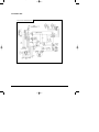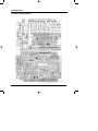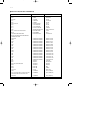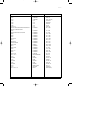
1
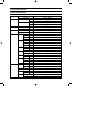
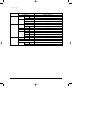
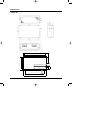
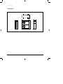
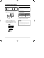
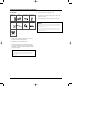
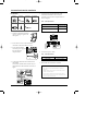
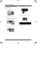
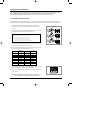
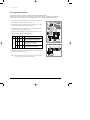
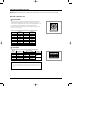
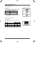
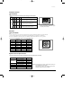
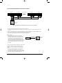
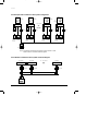
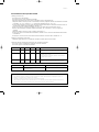
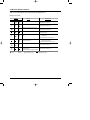
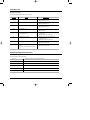
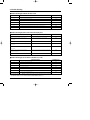
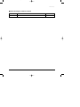
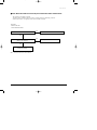
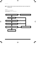
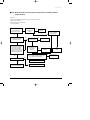
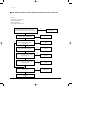
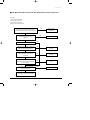
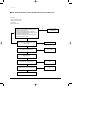
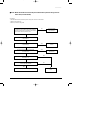
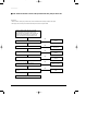
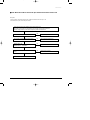
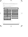
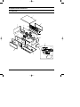
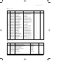
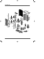
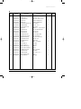
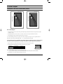
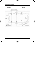
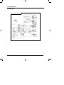
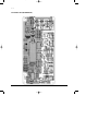
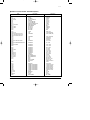
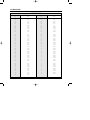
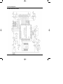
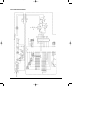
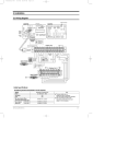
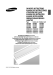
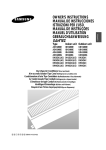
1-00216A(1)-CO
5/19/01 10:04 AM
Page 2
DUCT TYPE AIR CONDITIONER
(Cool)
TYPE
INDOOR UNIT
OUTDOOR UNIT
ADH4400G
IDH4400A
DH44ZA1(A2) DH44ZA1(A2)
SERVICE
UDH4400G
DH44ZAX
Manual
AIR CONDITIONER
CONTENTS
1. Product Specifications
2. Installation
3. Operating Instructions
4. Troubleshooting
5. Disassembly and Reassembly
6. Exploded Views and Parts List
7. Schematic Diagrams
2-00216A(1)-PR
5/19/01 10:04 AM
Page 1-1
1. Product Specifications
1-1 Table of Specifications
INDOOR UNIT
IDH4400G / DH44ZA1(A2)
OUTDOOR UNIT
UDH4400G / DH44ZAX
MODEL
Capacity
Cooling
Heating
Btu/h
45,000
W
13,200
Btu/h
54,900
W
16,100
Power supply
Power input
Running current
3ø 380-415V~ 50Hz
Cooling
kW
4.8
Heating
kW
5.3
Cooling
A
8.5
Heating
A
9.2
Indoor
Fan speed
H.H
r.p.m
940
unit
(at 0mmAq)
Hi
r.p.m
880
Med
r.p.m
850
Low
r.p.m
790
Air
H.H
m /min
36
circulation
Hi
m /min
34
Med
m /min
32
Low
m /min
30
Hi
dB(A)
49
(Sound
Med
dB(A)
48
pressure)
Low
dB(A)
47
Noise Level
3
3
Wave fin coil
row x stages x fin pitch
3 x 14 x 1.7(900mm)
type
Siroco
Fan
motor output
W
211
H
mm
390
W
mm
1,110
D
mm
650
Weight
kg
Net/Gross
70/78
Fan speed
Hi
r.p.m.
900
Low
r.p.m.
500
m /min
90
dB(A)
65
Dimensions
Outdoor
3
type
Heat
exchanger
3
unit
3
Air circulation (Hi)
Sound pressure level
Fan
motor output
Compressor
Samsung Electronics
propeller
type
W
114
type
scroll
model
ZR61KC-TFD
1-1
2-00216A(1)-PR
5/19/01 10:04 AM
Page 1-2
Product Specifications
INDOOR UNIT
IDH4400G / DH44ZA1(A2)
OUTDOOR UNIT
UDH4400G / DH44ZAX
MODEL
Outdoor
Compressor
motor output
unit
kW
protection
Internal
type
wave fin coil
Heat
row x stages x fin pitch
exchanger
face area
Condition
Capillary
4,000
(H x W x D)
mm
1,240 x 930 x 385
kg
Net/Gross
123/133
Cool(DB/WB)
˚C
27/19
Heat(DB/WB)
˚C
20/15
Cool(DB/WB)
˚C
35/24
Heat(DB/WB)
˚C
7/6
Liquid
mm(inch)
9.52(3/8”)
Gas
mm(inch)
19.05(3/4”)
Pipe O.D.
size
Flare
Connection method
Between
1.122
g
Weight
Piping
2 x 48 x 1.7(935/915)
(R22)Charge
Dimensions
Outdoor unit
m
2
control
Refrigerant
Indoor unit
3.79
Height
m
Max. 25
Pipe length
m
Max. 50
Notice : This model is tested under the external static pressure of 14mmAq
1-2
Samsung Electronics
2-00216A(1)-PR
5/19/01 10:04 AM
Page 1-3
1-2 Dimensions
• Indoor unit
1023
1042(Space of suspension bolts)
Electrical
component box
Pipe connection port
Inspection area
1200mm
Drain pipe connection port
936 x 321(Dimension of inlet duct flange)
Inspection area
1200mm
(Out diameter:ø27.2mm)
157
(Liquid pipe:ø9.52mm, Gas pipe:ø19.05mm)
131
650(Outer dimensions)
698(Space of suspension bolts)
936 x 321(Dimension of outlet duct flange)
1110(Outer Dimensions)
Samsung Electronics
1-3
2-00216A(1)-PR
5/19/01 10:04 AM
Page 1-4
Product Specifications
• Outdoor Unit
415
840
385
;;;;;;;
;;;;;;;
;;;;;;;
;;;;;;;
;;;;;;;
;;;;;;;
;;;;;;;
;;;;;;;
;;;;;;;
;;;;;;;
;;;;;;;
;;;;;;;
;;;;;;;
;;;;;;;
;;;;;;;
;;;;;;;
;;;;;;;
;;;;;;;
;;;;;;;
;;;;;;;
;;;;;;;
;;;;;;;
;;;;;;;
;;;;;;;
;;;;;;;
;;;;;;;
;;;;;;;
;;;;;;;
;;;;;;;
1-4
1420
930
Samsung Electronics
2-00216A(1)-PR
5/19/01 10:04 AM
Page 2-1
2. Installation
2-1 Wiring diagram
CN20 Connector
DIP Switch
MAIN PCB
SUB PCB
SW2
CN7
Rotary
Digital
Switch
SW1
Jumper
Wire
CN9
Receiver &
Display Unit
(Optional)
Indoor Unit
Transmitter
(Optional)
Ventilator
Motor
Float Switch
MAIN POWER
Wired
Remote
Controller
(Optional)
Centralized
Controller
(Optional)
Power
Earth
Drain Pump
Communication
220-240V~,
50Hz
Float Switch
Drain Pump
(Optional)
Outdoor Unit
MAIN POWER
3ø, 380-415V~,
50Hz
Cable Specifications
The following electrical characteristics must be respected.
MODEL
Power
Sub switch
Fuse
Min. size of electric Wires
from/to the indoor/outdoor unit
Size of electric
input wires
Samsung Electronics
20m or less
50m or less
ADH4400G / DH44ZA1(A2)
3Ø, 380-415V~, 50Hz
30A
30A
H07RN-F, 4G, 1.25mm2
H07RN-F, 3G, 2.5mm2
H07RN-F, 3G, 4.0mm2
Note
◆ The power cables are not
supplied with the air conditioner.
The user should purchase them separately.
◆ When connecting the cables to the
main power, you should connect each
cable(L1, L2 & L3) properly.
2-1
2-00216A(1)-PR
5/19/01 10:04 AM
Page 2-2
2-2 Wired Remote Controller Installation
Accessories
Wired Remote
Controller(1)
Cable-Tie(2)
Cable Clamp(5)
M4 X 16 Tapped
Screw(7)
Caution :
• Do Not keep the wired remote controller cables with a
220V cable because the remote controller cables have
low voltage.
• Do Not input 220V power to the R1, R2 and R3 in the
wired remote controller.
1. Disassemble the wired remote controller by
using two grooves on the top of it.
Note : Cable Specifications
Cable type
Size of cables
Max. length of electric wires from
the indoor unit to the wired remote
controller
Double-insulation, 3G
0.3mm2~0.75mm2
100m
4. Reassemble the wired remote controller.
2. Secure the rear cover of the wired remote
controller on the wall with two screws.
3. Connect the R1, R2 and R3 terminals in the
wired remote controller to the R1, R2 and R3
terminals on the electrical component box each.
Caution :
• The optional kits must be installed by an installation
specialist.
• Before installing the optional kits, ensure that you have
turned off the main power.
• All optional kits cables should be installed according to
the national wiring rules and you must install them in the
wall not to be touched by users.
Wired
Remote
Controller
2-2
Samsung Electronics
2-00216A(1)-PR
5/19/01 10:05 AM
Page 2-3
2-3 Wireless Remote Controller Installation
4. Close the receiver & display unit.
Accessories
Wireless Remote
Controller(1)
Battery(2)
M4 X 16 Tapped
Screw(2)
Remote Controller
Holder(1)
5. Secure the receiver & display unit on the wall
with two screws.
6. Reassemble the receiver & display unit cover.
Receiver &
Display Unit(1)
Cable-Tie(2)
Cable Clamp(5)
M4 X 16 Tapped
Screw(7)
Caution :
•The optional kits must be installed by an installation specialist.
•Before installing the optional kits, ensure that you have turned
off the main power.
Wire Kit
•All optional kits cables should be installed according to the
national wiring rules and you must install them in the wall not
to be touched by users.
Length : 10m
1. Remove the receiver & display unit cover by
using the tab on the bottom of it.
2. Open the receiver & display unit.
3. Connect the end of the connector wire to the
receiver & display unit and connect the other
end of the wire to the electrical component box
as shown in figure.
Caution :
•Do NOT keep the receiver & display unit cables with a
220V cable because the remote controller cables have
low voltage.
Samsung Electronics
2-3
2-00216A(1)-PR
5/19/01 10:05 AM
Page 2-4
2-4 Centralized Controller Installation
Accessories
Centralized
Controller(1)
Cable-Tie(2)
Cable Clamp(5)
M4 X 16 Tapped
Screw(7)
5. Connect the O1 and O2 terminals of the
centralized controller to the O1 and O2
terminals on the electrical component box as
shown in figure.
Note : Cable Specifications
Transmitter(1)
Spacer Support(4)
Cable-Tie(2)
M4 X 16 Tapped
Screw(7)
Cable type
Double-insulation,
2G(Shield Cable)
Size of cables
0.75mm2~1.25mm2
Max. length of electric wires from the
indoor unit to the centralized controller
1km
1. Open the centralized controller
cover by using two grooves on
the top of it.
2. Secure the rear cover of the centralized
controller on the wall with two screws.
3. Secure the transmitter
with four spacer supports
into the electrical
component box.
Centralized
Controller
6. Connect the power cables.
Note : Cable Specifications
Electrical component box
Transmitter
4. Connect the cable from the PCB and to the
transmitter.
And connect another cable from the O1, O2
terminals and to the transmitter as shown in
figure.
Cable type
Double-insulation, 2G
Size of cables
0.75mm2~1.25mm2
7. Reassemble the centralized controller.
Caution :
•The optional kits must be installed by an installation
specialist.
•Before installing the optional kits, ensure that you have
turned off the main power.
•All optional kits cables should be installed according to
the national wiring rules and you must install them in the
wall not to be touched by users.
2-4
Samsung Electronics
2-00216A(1)-PR
5/19/01 10:05 AM
Page 2-5
2-5 Air Filter Installation
1. Remove the air inlet duct flange.
3. To clean the air filter, remove the fixing bracket
on the base of air filter kit, then pull out the
filter.
2. Attach the air filter kit to the air inlet side of
indoor unit.
Note: Setting Up Filter Cleaning Cycle
• Adjust the DIP switch(SW2) in the main PCB to
the desired position referring the table below.
Switch No.
Switch Position
Filter Cleaning Cycle
4
ON
OFF
1,000 hours
2,000 hours
Caution :
•The optional kits must be installed by an installation
specialist.
•Before installing the optional kits, ensure that you have
turned off the main power.
•The optional air filter has to be cleaned only by an
authorized person or service agent.
Samsung Electronics
2-5
2-00216A(1)-PR
5/19/01 10:05 AM
Page 2-6
2-6 Drain Pump Installation
Care must be taken when installing the drain hose for
the indoor unit to ensure that any condensate water is
correctly drained outside.
4. Connect the cable to the electrical component
box as shown in figure.
1. Open the side of indoor unit.
Drain pump
Float
switch
5. Adjust the DIP switch(SW2) on the main PCB
according to the table below.
2. Screw the drain pump with two screws.
Note : When installing the drain pump, leave a 7mm
space between the bottom of the drain pan and
the drain pump.
Drain pump
Switch No.
Switch Position
2
3
ON
ON
Note : Wrap the drain tube outlet with an insulating
materials.
3. Connect the drain hose to the drain socket.
Drain pump hose
2-6
Samsung Electronics
2-00216A(1)-PR
5/19/01 10:05 AM
Page 2-7
2-7 Group Control Installation
* You should adjust the option switches in the electrical component box or on the PCB of the wired remote controller.
* Before setting up the option switches, always make sure that you have turned off the main power.
* After adjusting the options, you should supply the power. Otherwise, the options will not be applied.
2-7-1. With Wired Remote Controller
A user can operate up to sixteen air conditioners by using the wired remote controller In this case, the air conditioner can
be controlled by only one wired remote controller connected to the indoor unit and cannot be controlled by the others.
1. Connect the R1, R2 and R3 terminals in the wired remote
controller to the R1, R2 and R3 terminals in any indoor unit
“A” each.
2. Connect the R1 and R3 terminals in the indoor unit “A” to the
R1 and R3 terminals in another indoor unit “B”.
Unit A
CN20
Connector
Unit B
Caution :
When connecting the cables, you must keep these :
• The R1 terminals must be connected to the R1s.
• The R3 terminals must be connected to the R3s.
• Do not connect the R2 terminals to anywhere.
• If you connect R2 terminals, the PCB will be damaged.
Unit C
3. Connect the R1 and R3 terminals of “B” to any indoor unit
“C” and connect the others as the same way.
4. Remove the CN20 connectors on the sub PCBs except the unit
connected with remote controller(Adress “0”).
Switch No.
Number of
indoor unit(s)
Switch No.
Number of
indoor unit(s)
0
One
8
Nine
1
Two
9
Ten
2
Three
A
Eleven
3
Four
B
Twelve
4
Five
C
Thirteen
5
Six
D
Fourteen
6
Seven
E
Fifteen
7
Eight
F
Sixteen
5. Remove the CN20 connectors on the sub PCBs except the unit
connected with remote controller(Address “0”).
6. Adjust the DIP switch No. 2 in the wired remote controller to
“ON” position.
Note : You cannot install the centralized controller when the wired
remote controller for a group has already been installed.
Samsung Electronics
2-7
2-00216A(1)-PR
5/19/01 10:05 AM
Page 2-8
Product Specifications
2-7-2. With Centralized Controller
A user can turn on/off up to sixteen air conditioners by using the centralized controller.
In this case, the user can turn on/off all air conditioners or a specific air conditioner connected with the centralized
controller. And each air conditioner can be controlled by its own remote controller(s) depending on the setting.
1. Connect the O1 and O2 terminals in the centralized controller to
the O1 and O2 terminals in the indoor unit “A”.
2. Connect the O1 and O2 terminals in the indoor unit “A” to the
O1 and O2 terminals in another indoor unit “B”.
3. Connect the O1 and O2 terminals of “B” to any indoor unit “C”
and connect the others as the same way.
4. Adjust the DIP switch(DS01) in the centralized controller to the
desired position referring to the table below.
Switch
No.
1
2
3
4
Meaning
The air conditioner is operated by the controller
Centralized
Controller
OFF OFF OFF OFF adjusted last among the wired remote controller,
wireless remote controller and centralized controller.
Switch
OFF OFF OFF ON
Position
OFF OFF ON
A user can use wired/wireless remote controller when
the centralized controller is switched on.
And he/she cannot use the remote controller(s) when
the centralized controller is switched off.
Unit A
Unit B
Unit C
The air conditioner(s) can be controlled by only the
OFF centralized controller. The user cannot use the
wired/wireless remote controller in this case.
5. Adjust the rotary switch on the transmitter to the desired position
referring to the table on page 2-11.
Centralized
Controller
Note : You cannot install the centralized controller when the wired remote
controller for a group has already been installed.
2-8
Samsung Electronics
2-00216A(1)-PR
5/19/01 10:05 AM
Page 2-9
2-8 Setting Up Option Switches
IMPORTANT : Before setting up the option switches, always make sure that you have turned off the main power.
Main PCB in the Indoor Unit
Rotary Switch(SW1)
A user can operate up to sixteen air conditioners by using the wired remote
controller. Before controlling more than one air conditioner, you should
connect the air conditioner each other. And you must assign addresses to the
air conditioners. For further details on connecting air conditioners.
If the user would like to controller only one air conditioner, make sure that
the arrow is at “0” position.
Turn the arrow to the desired position referring to the table below.
Switch No.
Number of
indoor unit(s)
Switch No.
Number of
indoor unit(s)
0
One
8
Nine
1
Two
9
Ten
2
Three
A
Eleven
3
Four
B
Twelve
4
Five
C
Thirteen
5
Six
D
Fourteen
6
Seven
E
Fifteen
7
Eight
F
Sixteen
DIP Switch(SW2)
Adjust the switch to the desired position referring to the table below.
Switch
No.
Option Item
Switch Position
ON
OFF
Note
1
Ventilator Fan
Not installed
Installed
Not supplied
2
Drain Pump
Installed
Not installed
3
Float Switch
Installed
Not installed
Optionally
supplied
4
Filter Cleaning Cycle
1,000 hours
2,000 hours
5
Indoor Fan Motor Speed Normal
High speed
Caution :
• If you do not adjust the switch when not installing the drain pump, "✳9" error
will occurs. If this happens, adjust the No.2 and No.3 switches to the "OFF"
position.
Samsung Electronics
2-9
2-00216A(1)-PR
5/19/01 10:05 AM
Page 2-10
Setting Up Option Switches (Cont.)
Sub PCB in the Indoor Unit
CN20 Connector
Remove the CN20 connector in the sub PCB, if necessary, referring to the
table below. (This procedure is needed only when the user would like to
control a group by using the wired remote controller.)
Address
Situation of the CN20 Connector
0
Connected
1-F
Removed
Unit A
(Address 0)
CN20 Connector
Unit B
(Address 1)
Unit C
(Address 2)
Note : ◆ Up to 16 air conditioners can be controlled with one wired remote
controller.
Note : ◆ If the user does not want to control a group, do not remove the
CN20 Connector.
PCB in the wired remote controller
Dip Switch(DS01)
Adjust the DIP switch to the desired position referring to the table below.
Switch
No.
2-10
Option Item
1
Type of unit
2
Number of air conditioner(s) controlled
by the wired remote controller
3
Basic specification
4
Using wireless remote controller
Switch Position
ON
OFF
Cooling only
Heat pump
Group
controlling
One indoor unit
controlling
-
O
Can be used
Cannot be used
Samsung Electronics
2-00216A(1)-PR
5/19/01 10:05 AM
Page 2-11
Installation
Centralized Controller
DIP Switch(DS01)
Adjust the DIP switch to the desired position referring to the table below.
Switch
No.
1
2
3
4
Meaning
The air conditioner is operated by the controller
OFF OFF OFF OFF adjusted last among the wired remote controller,
wireless remote controller and centralized controller.
Switch
OFF OFF OFF ON
Position
A user can use wired/wireless remote controller when
the centralized controller is switched on.
And he/she cannot use the remote controller(s) when
the centralized controller is switched off.
The air conditioner(s) can be controlled by only the
OFF OFF ON OFF centralized controller. The user cannot use the
wired/wireless remote controller in this case.
Note : You cannot install the centralized controller
when the wired remote controller for a group
has already been installed.
Transmitter
Rotary Switch(DS01)
A user can turn on/off up to sixteen air conditioners by using the centralized controller. To use the controller,
you must assign addresses to the air conditioners. For further details on connecting air conditioners.
If the user would like to controller only one air conditioner, make sure that the arrow is at “0” position.
Turn the arrow to the desired position referring to the table below.
Switch No.
Number of
indoor unit(s)
Switch No.
Number of
indoor unit(s)
0
One
8
Nine
1
Two
9
Ten
2
Three
A
Eleven
3
Four
B
Twelve
4
Five
C
Thirteen
5
Six
D
Fourteen
6
Seven
E
Fifteen
7
Eight
F
Sixteen
Original Position of Option Switches
The option switches are preset by the manufacturer. Refer to the table below, if necessary.
Option Place
Main PCB in the
indoor unit
Component No.
State
Rotary Switch(SW1)
0
DIP Switch(SW2)
ON
Jumper Wire(SW05)
SHORT
Sub PCB in the indoor unit
CN20 Connector
Connected
Wired Remote Controller
DIP Switch(DS01)
OFF
Centralized Controller
DIP Switch(DS01)
OFF
Transmitter
Rotary Switch(DS01)
0
Samsung Electronics
Note : Before setting up the options, always make sure that you
have switched off the main power.
Note : After adjusting the options, you should supply the power.
Otherwise, the options will not be applied.
2-11
2-00216A(1)-PR
5/19/01 10:05 AM
Page 2-12
MEMO
2-12
Samsung Electronics
2-00216A(1)-PR
5/19/01 10:05 AM
Page 3-1
3. Operating Instructions
3-1 Example of Single unit Operation
1 chamber wired, wireless remote controller single operation and 1 chamber wireless remote controller +
wired remote controller combination control
Outdoor unit
Outdoor unit
Outdoor unit
Indoor unit
Indoor unit
Indoor unit
Wired
remote
controller
Receiver
& display
unit
Receiver
& display
unit
Wireless
remote
controller
Wired remote
controller
Wireless
remote
controller
Example of 1 chamber single operation
(wired or wireless remote controller)
Example of 1 chamber single operation
(wireless + wired remote controller)
* In case of 1 chamber single operation (wireless remote controller+wired remote controller), both setting of wired remote controller
to MASTER/SLAVE is available.
<To use wired & wireless remote controller simultaneously >
1. Put off the power.
2. For the combined use of wireless remote
controller and wireless remote controller, put on
the option switch 4 of wired remote controller.
3. Putting off the option switch 4 of wired remote
controller disables the control by wireless remote
controller.
4. Put on the power.
Caution :
• After resetting the option in the wired remote controller, be
sure to put the power on again so that the set option can
be applied.
Wired Remote Controller Option Switch
DIP SWITCH NO
OPTION ITEM
SW ON
SW OFF
DEFAULT
1
Type of unit
Cooling only
Heat pump
OFF
2
Indoor unit control
Group control
Indoor unit 1 chamber control
OFF
3
Basic specification
-
-
Fixed to OFF
4
Combined use of
wireless remote
controller
Able to operate of wired
remote controller
(SLAVE MODE)
Disable to operate the
wireless remote controller
(MASTER MODE)
OFF
Samsung Electronics
3-1
2-00216A(1)-PR
5/19/01 10:05 AM
Page 3-2
3-2 Exampe of Group Control Operation
3-2-1 Group Control with wired remote controller
Outdoor unit
Outdoor unit
"A" chamber
Indoor unit
"B" chamber
"O" chamber
"C" ~"N" chamber
Indoor unit
Receiver
& Display
unit
Receiver
& Display
unit
Receiver
& Display
unit
Receiver
& Display
unit
Wireless
remote
controller
Wireless
remote
controller
Wireless
remote
controller
Wireless
remote
controller
Wired remote
controller
"P" chamber
Wired remote
controller
Wired remote
controller
Wired remote
controller
Figure. 16 Chamber Group Control (Wireless remote controller + wired remote controller) System
• The 16 chamber remote controller operation by wired remote controller can be simultaneously performed
all for 16 chambers through setting the 16 chambers to one group through one wired remote controller.
• While operated in Group, the control by wireless remote controller installed in all chambers (“A” ~ “P”)
is disabled except the wired remote controller installed in the “A” chamber and the simultaneous use
with the option item, the centralized controller is also disabled.
3-2-2 The group operation method by wired remote controller
1. Setting of indoor unit Main PCB
• Put off all of set power installed in each room.
• Remove the centralized controller if any is used
already.
• Connect the communicating line from “A”
chamber to “P” chamber.(R1<->R1, R3<->R3)
• Connect the “R1”, “R2” and “R3” of indoor
terminal board installed to the “R1”,”R2”,”R3”
of wired remote controller, respectively.
• Adjust the address of rotary switch of indoor
unit PCB in “A” chamber to “0”.
3-2
1. Setting of indoor unit Main PCB
• Remove CN20 connector from main PCB of
Indoor unit except the one installed in “A” with
reference of the figure.
• Adjust the address of rotary switch of indoor unit
PCB in “B” chamber to “1”. In such a way, adjust
the address of digital switch up to chamber “P”.
• Put on the set power installed in each chamber.
Samsung Electronics
2-00216A(1)-PR
5/19/01 10:05 AM
Page 3-3
Installation
Caution :
• During the connection, connect the “R1” of indoor unit terminal board installed in each chamber with “R1”.
• During the connection, connect the “R3” of indoor unit terminal board installed in each chamber with “R3”.
• Do not connect the terminal R2 of indoor unit terminal board from “B” to “F” chamber except “A” chamber.
• The option item, centralized controller shall be removed since the simultaneous use with wired remote controller is disable
during the group control.
• Adjust the address of indoor unit rotary switch installed in each chamber so that it might not be duplicated.
2. Setting of wired remote controller
• Put off the set power where the wired remote controller is installed.
• Put on the option switch SW 2 of wired remote controller.
• Put on the set power where the wired remote controller is installed.
Caution :
• The option can be applied when the power is put again after resetting the option of wired remote controller. Be sure to keep the
set power on/off after option setting.
Samsung Electronics
3-3
2-00216A(1)-PR
5/19/01 10:05 AM
Page 3-4
Installation
3-2-3 Group Operation method of wired remote controller
"A" chamber
"B" chamber
Indoor unit
Indoor unit
R1 R2 R3
"C" ~ "N" chamber
R1 R2 R3
"O" chamber
"P" chamber
Indoor unit
Indoor unit
R1 R2 R3
R1 R2 R3
R1 R2 R3
Wired remote
controller
Figure. 16 Chamber Group Control(wired remote controller) Connection Diagram
• Press the ON/OFF button of wired remote controller to be on.
At the time, the set installed from A chamber to P chamber is getting on in order with the interval of 2
seconds.
• Select the operation of auto/cooling/dehumidi-fying/blowing/heating by pressing MODE BUTTON.
• Select breeze/mild/strong wind by pressing the wind volume button.
• Adjust the temperature set button to set the desired temperature.
✽ For reference
• The communication between wired remote
controller and indoor unit is made through the
synchronization with the output signal of zero
cross detect circuit, and when 50Hz power is
used, it has the 50bps transmission speed and
when it has 60Hz power it has 60bps transmission
speed. The transmission data between the wired
remote controller and indoor unit is shown as in
the figure.
RECEIVE MODE
Indoor unit
Wired remote
controller
SEND MODE
Since the communication data between wired remote
controller and indoor unit is consisting of total
10Byte, 2 seconds are required when using 50Hz
power.
• For the communicating time with 16 chambers
during the normal operation, 32 seconds are
required and for the time with 16 chamber during
the reservation operation, 64 seconds are required
due to the increase of communicating data.
3-4
Samsung Electronics
2-00216A(1)-PR
5/19/01 10:05 AM
Page 3-5
Installation
3-2-4 Startup method by wired remote controller
Start up of single operation
• Put on the set power.
• Adjust the address of digital switch of indoor
unit PCB to “0”.
• Put OFF the option switch 2 of wired remote
controller PCB.
• Put on the set power.
• Press the test button of wired remote controller
for more than 3 seconds.
Error Code
• The set is operated for 3 minute by the forced
cooling operation and the set is off after 3
minute.
• The error occurring during the test operation is
displayed on the wired remote controller
windows and it shall be referred to the
following table.
Meaning
Checking Area
01
Indoor unit room thermistor error
• Indoor unit thermistor available or not and
disconnected
• Indoor unit PCB
05
Indoor unit pipe thermistor error
• Indoor unit pipe thermistor
• Indoor unit PCB
06
Outdoor unit thermistor error
• Outdoor unit thermistor
• Outdoor unit PCB
09
Float switch open error
• Drain pump, float switch
• Drain system
• Dip SW2 of indoor unit main PCB
(If the drain pump is not installed, SW2 and
SW3 shall be at the Off position.)
0A
Indoor unit ↔ outdoor unit communicating error
• Indoor unit ↔ outdoor unit communicating
error
• Indoor unit ↔ outdoor unit communicating
cable
• Indoor unit PCB, Outdoor unit PCB
0C
Wired remote controller ↔ indoor unit
communication error
• Wired remote controller ↔ indoor unit
communication cable
• Indoor unit main PCB
0D
Outdoor unit pipe thermistor error
• Outdoor unit pipe thermistor
• Outdoor unit PCB
0L
Three phase power incorrect connecting error
• Three phase power connecting
• Outdoor unit PCB
Caution :
• Unless the address of digital switch of indoor unit PCB is set to “0” in case of “A” chamber single operation, the control by the wired
remote controller is disabled.
• The power of SET shall be put on again after the resetting of wired remote controller option so that the the set option can be applied.
Be sure to keep the power on/off of SET before and after the setting.
• The first digit of error code displayed during the single operation and group operation may be different. The first digit(MSB) stands for
the address of the set where the error occurs. Since it is the single operation, the address of SET is “0”.
Samsung Electronics
3-5
2-00216A(1)-PR
5/19/01 10:05 AM
Page 3-6
Installation
Startup of group operation
• If the current SET of chamber “A” is ON, put the
set off by pressing the ON/OFF button.
• Put off the power of SET.
• Adjust the addresses of digital switch of indoor
unit PCB to “0”~”15”, respectively.
• Put ON the option switch SW2 of wired remote
controller PCB.
• Put on the power of SET.
• On the wired remote controller display, the digits
“00” → “11” → “22” → are displayed up to “FF”.
After “FF” display, the wired remote controller is
automatically set to the preserved operation
status of indoor unit of chamber “A”.
Error Code
Only at the SET off of chamber “A”, the TEST mode
is enabled.
• Press the TEST BUTTON of wired remote
controller for more than 3 seconds.
• If the SET is operating for 3 minutes through
forced cooling operation, the SET is off after 2
minutes.
• The Error occurring in the TEST operation
displays in the wired remote controller display
window and is referred to the following table.
Checking Area
Meaning
*1
Indoor unit room thermistor error
• Indoor unit thermistor exist or not disconnected
• Indoor unit PCB
*5
Indoor pipe thermistor error
• Indoor unit pipe thermistor
• Indoor unit PCB
*6
Outdoor unit thermistor error
• Outdoor unit thermistor
• Outdoor unit PCB
*9
Float switch open error
• Drain pump, float switch
• Drain system
• Dip SW2 of indoor unit main PCB
(If drain pump is not installed, SW2 and SW3
shall be at OFF position.)
*A
Indoor unit ↔ outdoor unit communication error
• Indoor unit ↔ Outdoor unit communication cable
• Indoor unit PCB, outdoor unit PCB
*C
Wired remote controller ↔ indoor unit
communication error
• Wired remote controller ↔ indoor unit
communication cable
• Indoor unit main PCB
*D
Outdoor unit pipe thermistor error
• Outdoor unit pipe thermistor
• Outdoor unit PCB
*L
Three phase power incorrect connecting error
• Threem phase power connecting
• Outdoor unit PCB
Caution :
• Test operation is disabled when the chamber “A” is on after initialization of wired remote controller.
• The communication time between wired remote controller and indoor unit is required for 2 seconds. If any one of set is ON, be sure to
put it off by pressing the ON/OFF button and start the TEST operation after 35 seconds at minimum.(The communication time with all
chambers : 16 x 2 seconds = 32seconds)
• For the reservation operation, the communication time between all 16 chambers is required for 64 seconds due to the increase of
communication data.
• The first digit (MSB) of error code displayed during the group operation stands for the address of SET where the error occurs.
3-6
Samsung Electronics
2-00216A(1)-PR
5/19/01 10:05 AM
Page 3-7
3-3 Centralized Controller Operation
3-3-1 Appearance and characteristics of Centralized Controller
The centralized controller is installed on the wall.
The centralized controller is an optional accessory.
Operating lamp
All On button
All Off button
On/Off indicators
On/Off buttons
Index
NOTE : Operating lamp comes on when at least one air conditioner
connected to the centralized controller is operating.
• Since the centralized controller has the relay
equipment, the option mounted on the indoor
unit, the On/Off can be set for 16 chambers
through the modem communication.
• Linkage of wired remote controller to wired
remote controller is available by 3 kinds of level.
• The maximum extended distance of 1 Km is
possible through modem communication. (the
relay equipment is installed at the option item,
indoor unit)
• The connection by non-polarity method is easy.
BUTTON NAME
FUNCTION
ALL1
• To put on all 16 chambers' set.
ALL0
• To put off all 16 chambers' set.
"01" ~ "16"
Samsung Electronics
• To put on/off set assigned with the number.
3-7
2-00216A(1)-PR
5/19/01 10:05 AM
Page 3-8
Installation
3-3-2 Example of the centralized control system configuration
Outdoor unit
Outdoor unit
"A"
chamber
Outdoor unit
"B"
chamber
Outdoor unit
"O"
chamber
"P"
chamber
"C" ~"N" chamber
Indoor unit
Indoor unit
Indoor unit
Indoor unit
16
chamber
Transmitter
Receiver
& Display
Unit
Wireless
remote
controller
Wired remote
controller
Transmitter
Receiver
& Display
Unit
Wireless Wired remote
remote
controller
controller
Receiver
& Display
Unit
Wireless Wired remote
remote
controller
controller
Transmitter
Receiver
& Display
Unit
Transmitter
Wireless Wired remote
remote
controller
controller
Centralized controller
Figure. 16 Chambers Centralized Control (wireless remote controller + wired
remote controller + centralized controller) System
3-3-3 Chambers centralized control system connection diagram
"A" chamber
"B" chamber
Indoor unit
Indoor unit
Indoor unit
01 02 Transmitter
01 02 Transmitter
01 02 Transmitter
"C" ~ "O" chamber
"P" chamber
01 02
3-8
Samsung Electronics
2-00216A(1)-PR
5/19/01 10:05 AM
Page 3-9
Installation
3-3-4 Centralized control operation method
1. Setting of indoor unit
• Put off the set to be installed.
• Put off the power of the centralized controller.
• Mount the transmitter, the option item on the indoor unit set terminal board.
• Adjust the address of rotary switch of transmitter mounted. (Adjust the address of transmitter mounted
in chamber “A” to “0” and “B” to “1”... continue the adjustment up to “P” to “F”)
• Connect the terminals O1 and O2 of the terminal board mounted on the centralized controller to the O1
and O2 of the terminal board installed in chamber “A”.
• If the wired remote controller is installed, be sure to put off the SW2 of PCB option switch.
• Remove the centralized controllers installed at chamber “B” to chamber “P” if any except the A
chamber.
• Adjust the address of rotary switch of indoor unit PCB to “0”.
• Connect O1 and O2 of terminal board installed in chamber A to O1 and O2 of terminal board installed
in chamber B.
• Continue to connect O1 and O2 of terminal board mounted on indoor unit in chamber B ~ P.
2. Setting at centralized control side
• Adjust the applicable level of centralized controller with the reference of the table.
3. When the setting is finished at indoor unit and centralized controller,
• Put on the power of installation completed set of each chamber.
• Put on the power of centralized controller.
REMARK
DIP SWITCH
SW1
SW2
SW3
SW4
LEVEL 0
OFF
OFF
OFF
OFF
Set operation according to the final controlled one among the
centralized controller, wire, and wireless remote controller
LEVEL 1
OFF
OFF
OFF
ON
When centralized controller OFF : disable to control wired and
wireless remote controller
When centralized controller ON : enable to control wired and
wireless remote controller
LEVEL 2
OFF
OFF
ON
OFF
Enable to control only in the centralized controller
Disable to control the wired and wireless remote controller
Error Code
LED flickering
Meaning
Communication error between indoor unit and
centralized controller
Checking Area
Transmitter, indoor unit, centralized controller
Caution :
• The communication between centralized controller and transmitter is modem method and there is no polarity but connect “O1”
terminal to “O1” terminal and “O2” terminal to “O2”terminal.
• The address of transmitter mounted on each indoor unit shall not be duplicated.
• After the resetting of operation level of centralized controller, it is not necessary to reset the power differently from that of wired
remote controller. In other words, the operation level can be reset even during the operation if required.
Samsung Electronics
3-9
2-00216A(1)-PR
5/19/01 10:05 AM
Page 3-10
MEMO
3-10
Samsung Electronics
3-00216A(1)-TS
5/19/01 10:06 AM
Page 4-1
4. Troubleshooting
4-1 Wired Remote Controller
If the error occurs,
and the error code are displayed on the wired remote controller.
The error code blinks for 5 seconds and it disappears. If you would like to see the error code after disappearing it,
press the Test button.
Meaning of Error Code
The error code is composed of two-digit figures or letters. The first means (∗) an indoor unit address and the second
means an error code.
Error Code
Meaning
∗1
Indoor unit thermistor sensor error
◆ Indoor unit thermistor sensor
◆ PCB of the indoor unit
∗5
Indoor unit pipe sensor error
◆ Indoor unit pipe sensor
◆ PCB of the indoor unit
∗6
Outdoor unit thermistor sensor error
◆ Outdoor unit thermistor sensor
◆ PCB of the outdoor unit
∗9
Float switch error
◆ Drain pump, Float switch
◆ Drain system
◆ DIP switch(SW2) of the indoor unit
(The No.2 and No.3 switches must
be at “ON” postion.)
∗A
A Indoor and Outdoor
communication error
◆ Communication cables of indoor and
outdoor units
◆ PCB of indoor and outdoor units
∗C
Wired remote controller communication
error
◆ Wired remote controller cables, Wired
remote controller
◆ Main/Sub PCB of the indoor unit
∗D
Outdoor pipe sensor error
◆ Outdoor pipe sensor
◆ PCB of the outdoor unit
∗L
Three phase power incorrect connecting
error
(In case of three phase power models)
◆ Three phase power connecting
◆ PCB of the outdoor unit
Checking area
Example : “39” means the address “3” indoor unit has a trouble with a float switch.
Samsung Electronics
4-1
3-00216A(1)-TS
5/19/01 10:06 AM
Page 4-2
4-2 Wireless Remote Controller
If the error occurs, the indicators on the receiver & display unit displays the error.
Meaning of Error Code
Indicators
Timer
▲
Operating
▲
▲
▲
: OFF
4-2
Meaning
Checking area
Filter
▲
▲
: Blinking
Indoor unit thermistor sensor error
◆ Indoor unit thermistor sensor
◆ PCB of the indoor unit
Indoor unit pipe sensor error
◆ Indoor unit pipe sensor
◆ PCB of the indoor unit
Outdoor unit thermistor sensor error
◆ Outdoor unit thermistor sensor
◆ PCB of the outdoor unit
Float switch error
◆ Drain pump, Float switch
◆ Drain system
Indoor and Outdoor communication
error
◆ Communication cables of indoor and
outdoor units
◆ PCB of indoor and outdoor units
Wired remote controller
communication error
◆ Wired remote controller cables,
Wired remote controller
◆ Main/Sub PCB of the indoor unit
Outdoor pipe sensor error
◆ Outdoor pipe sensor
◆ PCB of the outdoor unit
Three phase power incorrect
connecting error
(In case of three phase power models)
◆ Three phase power connecting
◆ PCB of the outdoor unit
▲ ▲ : Blinking at once
: Blinking alternately
Samsung Electronics
3-00216A(1)-TS
5/19/01 10:06 AM
Page 4-3
4-3 Outdoor Unit
Meaning of Error Code
Indicated in Outdoor PCB in case of error occured
Error Code
Meaning
E1
Indoor unit thermistor sensor error
◆ Indoor unit thermistor sensor
◆ PCB of the indoor unit
E5
Indoor unit pipe sensor error
◆ Indoor unit pipe sensor
◆ PCB of the indoor unit
E6
Outdoor unit thermistor sensor error
◆ Outdoor unit thermistor sensor
◆ PCB of the outdoor unit
E9
Float switch error
◆ Drain pump, Float switch
◆ Drain system
EA
A Indoor and Outdoor
communication error
◆ Communication cables of indoor and
outdoor units
◆ PCB of indoor and outdoor units
EC
Wired remote controller
communication error
◆ Wired remote controller cables, Wired
remote controller
◆ Main/Sub PCB of the indoor unit
ED
Outdoor pipe sensor error
◆ Outdoor pipe sensor
◆ PCB of the outdoor unit
EL
Three phase power incorrect connecting
error
(In case of three phase power models)
◆ Three phase power connecting
◆ PCB of the outdoor unit
Checking area
4-4 Reading temperature from sensor
Press tact switch on the outdoor PCB
Press once
Outside temperature from outdoor thermistor sensor
Press twice
Outdoor unit coil temperature from outdoor pipe sensor
Press three times
Defrost setting option/Power type
Press four times
Indoor unit coil temperature from indoor pipe sensor
Press five times
Indoor unit setting temperature
Press six times
Inside temperature from indoor thermistor sensor
Samsung Electronics
4-3
3-00216A(1)-TS
5/19/01 10:06 AM
Page 4-4
4-5 Trouble Shooting
■ Trouble shooting by outdoor unit error code
ERROR DESCRIPTION
ERROR CODE
REFERENCE PART
E1
Indoor unit room thermistor error
EC01
E5
Indoor unit pipe thermistor error
EC02
E6
Outdoor unit thermistor error
EC03
E9
Float switch open error
EC04
EA
Communication error between indoor unit and outdoor unit
EC05
EC
Communication error between wired remote controller and indoor unit
EC06
ED
Outdoor unit pipe thermistor error
EC07
■ Trouble shooting by indoor unit receiver & Display unit
ERROR CODE
ERROR CODE
REFERENCE PART
Reservation LED flickering(1Hz period)
Indoor temperature sensor abnormal
EC01
Operation LED and reservation LED flickering
Indoor pipe temperature sensor abnormal
EC02
Operation LED and filter LED flickering (1Hz period)
Outdoor temperature sensor abnormal
EC03
Reservation LED filter LED alternating flickering
Float switch open abnormal
EC04
Indoor and outdoor communication abnormal
EC05
Wired remote controller communication abnormal
EC06
Outdoor pipe temperature sensor abnormal
EC07
(1Hz period)
(1Hz period)
Reservation LED and filter LED flickering
(1Hz period)
Operation LED and reservation LED alternating
flickering (1Hz period)
Filter LED flickering (1Hz period)
■ Trouble shooting by wired remote controller error code
ERROR DESCRIPTION
ERROR CODE
REFERENCE PART
*1
Indoor unit room thermistor error
EC01
*5
Indoor unit pipe thermistor error
EC02
*6
Outdoor unit thermistor error
EC03
*9
Float switch open error
EC04
*A
Communication error between indoor unit and outdoor unit
EC05
*C
Communication error between wired remote controller and indoor unit
EC06
*D
Outdoor unit pipe thermistor error
EC07
✽ The asterisk mark “ * ” + “ERROR” CODE of wired remote controller stands for the set number.
ex) ERROR CODE “39” is the FLOAT SWITCH OPEN ERROR of SET no.3.
4-4
Samsung Electronics
3-00216A(1)-TS
5/19/01 10:06 AM
Page 4-5
Trouble Shooting
■ Trouble shooting by centralized controller
ERROR CODE
LED flickering
Samsung Electronics
ERROR DESCRIPTION
Communication error between indoor unit and centralized controller
REFERENCE PART
EC19
4-5
3-00216A(1)-TS
5/19/01 10:06 AM
Page 4-6
Trouble Shooting
■ EC01 : Trouble on the thermistor related part of indoor unit.
• EC01 : Trouble on the room thermistor related part of indoor unit.
- E1 of outdoor unit PCB 7-segment
- Reservation lamp of wireless receiving board is flickering with 1 Hz.
- Action items when “*1” displays on the wired remote controller.
Check point :
- Defect of indoor unit
- Indoor unit thermistor defect
NO
Indoor unit thermistor installed at CN8?
Indoor the indoor unit thermistor at CN8
YES
Is the vlotage across the thermistor 4.9V and
tabove or 0.5V and lower?
NO
Replace the indoor unit PCB
YES
Replace the thermistor
✽ “*” stands for the indoor unit address.
■ EC02 : Trouble on the pipe thermistor related part of indoor unit.
- E5 of outdoor unit PCB 7-segment.
- Reservation lamp of wireless receiving board is flickering with 1 Hz.
- Action items when “*5” displays on the wired remote controller.
Check point :
- Indoor unit PCB defect
- Indoor unit pipe thermistor defect
NO
Is the indoor unit pipe thermistor installed at CN8?
Install the indoor unit pipe thermistor at CN8
YES
Is the voltage across thermistor 4.9V and higher
or 0.5V lower?
NO
Replace the indoor unit
PCB
YES
Replace the thermistor
4-6
Samsung Electronics
3-00216A(1)-TS
5/19/01 10:06 AM
Page 4-7
Trouble Shooting
■ EC03 : When the trouble is found on the part related to the outdoor unit thermistor.
- E6 of outdoor unit PCB 7-segment
- Operation lamp and filter lamp of wireless receiving board are flickering with 1Hz.
- Action items when “*6” displays on the wired remote controller.
Check point :
- Defect of indoor unit
- Indoor unit thermistor defect
NO
Is the outdoor unit thermistor installed at CN41?
Install the outdoor unit thermistor at CN41.
YES
Is the voltage across the thermistor 4.9V and
higher or 0.5V and lower?
NO
Replace the outdoor unit PCB
YES
Replace the thermistor
✽ “*” stands for the indoor unit address.
Samsung Electronics
4-7
3-00216A(1)-TS
5/19/01 10:06 AM
Page 4-8
Trouble Shooting
■ EC04 : When the trouble is found on the drain pump and float switch installed on the
indoor unit.
EC01 : Trouble on the thermistor related part of indoor unit.
- E9 of 7-segment of outdoor unit PCB.
- Reservation lamp of wireless receiving board and filter lamp are flickering with 1 Hz.
- Action item when “*9” displays on the wireless remote controller.
Check point :
- Indoor unit defect
- Drain pump, float switch defect
Start
Is available drain
pump?
YES
YES
SW2 ON?
Is available float
SW?
YES
YES
SW3 ON?
Check the
float SW
Replace
indoor unit
PCB
NO
NO
SW2 ON?
Replace PCB
Install float SW
YES
SET SW2 OFF
SET SW3 OFF
SET SW2 OFF
SET SW3 OFF
POWER RESET
✽ “*” stands for the indoor unit address.
4-8
Samsung Electronics
3-00216A(1)-TS
5/19/01 10:06 AM
Page 4-9
Trouble Shooting
■ EC05 : When the trouble is found in the communication related part between indoor unit
and outdoor unit.
- EA of 7-segment of outdoor unit PCB.
- Reservation lamp and filter lamp of wireless receiving board is flickering with 1 Hz.
- Action item when “*A” displays on the wired remote controller.
Check point :
- Indoor unit ↔ outdoor unit mis-connection
- Indoor unit PCB defect
- Outdoor unit PCB defect
Are the terminals Na,Lb,C of indoor unit and outdoor unit
are correctly connected? and is the set power on?
NO
Do connection correctly and check.
YES
Is the LED of PCB flickering with 16Hz for 250ms and
then repeating the on?
YES
Indoor unit communication norma
NO
Is the LED of PCB flickering with 16Hz?
YES
The Micom of outdoor unit is operating normally,
check and replace the communication circuit of
outdoor unit and indoor unit.
NO
Replace the PCB
✽ “*” stands for the indoor unit address.
Samsung Electronics
4-9
3-00216A(1)-TS
5/19/01 10:06 AM
Page 4-10
Trouble Shooting
■ EC06 : When the trouble is found in the communication related part between indoor unit
and wired remote controller. (during single operation, not group control)
- EC of 7-segment of outdoor unit PCB.
- Wireless receiving board lamp and reservation lamp is flickering with 1Hz.
- Action item when “C” displays on the wired remote controller.
Check point :
- Short circuit or mis-connection of the communication line between indoor unit and wireless remote controller
- Indoor unit PCB defect
- Wired remote controller PCB defect
NO
Are the terminals R1, R2, R3 of indoor unit terminal
board connected correctly to R1, R2, R3 of wired remote
controller?
Connect correctly and check.
YES
Is 7P(RED) of transformer connected to CN11
of indoor unit?
Is the jump wire inserted into CN20 of indoor unit PCB?
NO
Connect correctly and check again
YES
NO
Is the address of PCB digital switch of indoor unit to "0"?
Set address to "0"
YES
NO
Replace the indoor unit PCB
Replace the wired remote controller
✽ “0” stands for the indoor unit address.
4-10
Samsung Electronics
3-00216A(1)-TS
5/19/01 10:06 AM
Page 4-11
Trouble Shooting
■ EC07 : When the trouble is found in the communication related part between outdoor
unit pipe thermistor.
- ED of 7-segment of outdoor unit PCB.
- Reservation lamp and filter lamp of wireless receiving board is flickering with 1Hz.
- Action item when “D” displays on the wired remote controller.
Check point :
- Indoor unit pipe thermistor available or not
- Indoor unit PCB defect
Is indoor pipe thermistor installed at CN41?
NO
Connect correctly and check.
YES
Is the voltage across the thermistor 4.9V and higher
or 0.5V and lower?
NO
Replace the outdoor PCB
YES
Replace the thermistor
✽ “*” stands for the indoor unit address.
Samsung Electronics
4-11
3-00216A(1)-TS
5/19/01 10:06 AM
Page 4-12
Trouble Shooting
■ EC08 : When the trouble is found on the part related to the wireless receiving board of
the indoor unit.
Check point :
- Defect of wireless remote controller PCB
- Defect of wireless remote controller receiving board PCB
- Indoor unit PCB defect
YES
Insert correctly
Mis-insertion of CN9?
NO
YES
Wire shorted?
NO
YES
LED direct/reverse direction check?
NO
NO
Check no.1 and no.2 pin of CN9:DC +5V?
YES
Check pin no.1 of CN9 while pressing
SW91 : DC 0V?
NO
Replace the wireless receiving board
YES
Replace after check of indoor unit
main PCB
4-12
Samsung Electronics
3-00216A(1)-TS
5/19/01 10:06 AM
Page 4-13
Trouble Shooting
■ EC09 : When the trouble is found on the part related to the wired remote controller.
(single operation)
Check point :
- Defect of communication line between indoor unit and wired remote controller.
- Output of indoor unit Micom
- Defect of wired remote controller PCB
- Indoor unit PCB defect
Is the wired remote
controller energized
when the power is reset?
NO
Is CN20 of indoor
unit main PCB
inserted?
NO
CN20
insertion
Is the wire of CN15 to
indoor unit terminal
board shorted?
YES
YES
NO
Is the on/off button command
of wired remote controller
reflected on the set?
NO
Is the address
of indoor unit "0"
YES
NO
Set to "0"
YES
When the power is applied
again after removing the
power at the operation on,
does the previous status
display on the wired remote
controller display window?
NO
YES
NO
Check the main PCB of
indoor unit and replace it.
Samsung Electronics
YES
One unit is
installed
Replace the
wiring
NO
YES
Does the error code display?
More than on indoor
unit mounted on the
wired remote
controller?
Are the terminals R1, R2, R3 of wired
remote controlled connected to the R1, R2,
R3 of indoor unit terminal boards?
YES
Check the indoor
unit PCB
NO
Connect correctly the R1, R2, R3
Error correction and recheck
4-13
3-00216A(1)-TS
5/19/01 10:06 AM
Page 4-14
Trouble Shooting
■ EC10 : When the trouble is found on the part related to the fan motor of indoor unit.
Chec point :
- Defect of PCB relay of indoor unit.
- Output of indoor unit Micom
- Indoor fan motor defect
- Defect of PCB IC06 of indoor unit
Is the power source normal? AC220 ~ 240 50Hz
Is the wire harness for motor connection good?
Is the terminal contact of fan motor condenser good?
NO
Check the replay part
and replace
YES
During the wind control, does it change
to breeze, mild and strong wind?
NO
Normal
NO
YES
When changing the wind to breeze,
mild and storing, do RY73, RY74,
RY75 operate?
NO
Check micom and
replace
NO
Is he output pin of micom high when
selecting each wind control mode?
NO
Check micom and
replace
NO
Check micom and
replace
NO
Check IC06 and
replace
YES
When selecting the each wind control
mode, is the voltage across the replay of
indoor unit PCB 12V?
YES
When selecting each wind control of
micom, are the pin 14 and 15 of indoor
unit PCB IC06 low?
YES
Is the voltage across the indoor unit fan
AC220 ~ 240V?
NO
Replace PCB
YES
Check the indoor unit fan motor
and replace
4-14
Samsung Electronics
3-00216A(1)-TS
5/19/01 10:06 AM
Page 4-15
Trouble Shooting
■ EC11 : When the trouble is found on the part related to the fan motor of outdoor unit.
Check point :
- Outdoor unit PCB relay defect
- Output of outdoor unit micom
- Outdoor unit fan motor defect
- Defect of IC07 of outdoor unit PCB
Is the power source normal? AC220~240 50Hz
Is the wire harness for motor connection good?
Is the terminal contact of fan motor condenser good?
NO
Check and replace
the related part
YES
YES
Does the outdoor fan motor changes to mild
and strong wind during the cooling
operation?
Normal
NO
YES
Do the RY73, RY74 operate?
NO
Is the wind volume output pin of micom high
when each wind control is operation?
NO
Check and replace
the micom
YES
Is the voltage across the PCB relay 12V
when the each wind control of micom
is opeating?
NO
Check and replace
the relay
YES
Are the pins 11 and 12 of IC07 of outdoor
unit PCB low when each wind control mode
micom is operation?
NO
Check and replace
IC07
YES
Is the voltage across the outdoor unit
fan motor AC220~240V?
NO
Replace PCB
YES
Check outdoor unit fan motor and replace
Samsung Electronics
4-15
3-00216A(1)-TS
5/19/01 10:06 AM
Page 4-16
Trouble Shooting
■ EC12 : When the trouble is found on the part related to comp of outdoor unit.
Check point :
- Indoor unit PCB relay defect
- Output of indoor unit micom
- Comp defect
- Magnet switch defect
Is the power source normal? AC220~240 50Hz
Is there no wrong connection and contact of indoor
and outdoor connection wire?
Is the compressor being delayed for 3 minutes?
Is the desired temperature set higher than the current
one during the cooling operation?
Is the desired temperature set lower than the current
one during the cooling operation?
NO
Check and replace
the related part
YES
Is the RY71 on and compressor operting
when cooling mode operates and indoor unit
PCB is shorted?
Normal
YES
Is the output of outdoor unit micom pin 57
high when the compressor is on?
Check and replace
micom (IC04)
Is the voltage across RY7 coil of
outdoor PCB 12V?
Is the output of NO. 10 of IC05 of outdoor
unit low then the compressor is on?
Check and replace
IC05
Is the voltage AC220V across the terminal
of outdoor unit when the compressor is on?
Replace the magnet
replay
Replace the compressor
4-16
Samsung Electronics
3-00216A(1)-TS
5/19/01 10:06 AM
Page 4-17
Trouble Shooting
■ EC13 : When the trouble is found on the part related to the up & down swing motor of
indoor unit (cassette model)
Check point :
- Wire short between indoor unit PCB up & down swing motor connector or bad contact.
- Output of indoor unit micom
- Defect of up and down swing motor
After check of the short circuit of harness for
connecting the up and down swing motor, operate the
set in the cooling mode and oeprate the wind direction
up and down, and then perform the test.
NO
Check and replace
the related part
Perform the operation on and do the up & down
swing action on.
Is the up & down control panel norm
ally operationg?
YES
Normal
NO
No short or wrong connection of connection
of connector wire?
YES
Check and replace
wire harness?
NO
Are the voltage of pin no. 1 and 6 of indoor
unit PCB DC 12V?
YES
NO
Is the output of pin no. 2, 3, 4, and 5 of CN 12 and 13
of indoor unit PCB spherical?
NO
YES
Replace up and down swing motor
Samsung Electronics
Replace indoor unit
PCB
4-17
3-00216A(1)-TS
5/19/01 10:06 AM
Page 4-18
Trouble Shooting
■ EC14 : When the trouble is found on the part related to drain pump of indoor unit.
Check point :
- Indoor unit PCB ↔ Drain pump connector wire, indoor unit Micom No.6 Pin output, IC06 No.6 Pin output.
- Drain pump, RY72, DC12V power, AC220~240V 50Hz power, indoor unit option switch.
Check to confirm whether the wire is connected
correctly between indoor unit and outdoor unit?
After checking of the shortage for the connector wire
between indoor unit and dran pump, operate it for
cooling, and checking compressor and then test it.
NO
Is normal the DC12V, DC5V output of indoor unit?
NO
Is switch on the No.2, No.3 option switch of indoor unit?
NO
Is “LOW” the No.6 pin output of IC04?
NO
Is “HIGH” the No.11 pin output of IC06?
Check IC01, IC02 and
replace.
Reset the power
after turn on.
Check IC06 and
replace.
Replace of indoor unit
micom
NO
Is DC12V the relay both voltage of RY72?
Is AC220V~AC240V of the No.1, No3 pin both voltage
of CN5.
Repace the RY72
NO
Replace the indoor
PCB.
Check the drain pump and replace.
4-18
Samsung Electronics
3-00216A(1)-TS
5/19/01 10:06 AM
Page 4-19
Trouble Shooting
■ EC15 : When the trouble is found on the part related to float switch of indoor unit.
Check point :
- Indoor unit PCB ↔ float switch connector wire, voltage level of indoor unit micom pin no. 55
- Float switch, DC5V power, indoor unit option switch
Is the wire connected correctly between indoor unit and outdoor unit?
After check of short circuit on the wire between indoor unit and connector wire of float switch,
start the cooling operation and then check compressor operation and start the test.
Is the DC5V of indoor unit normal?
NO
Check and replace IC02
YES
Are no.2 and 3 of option swithch of indoor unit on?
NO
Put on and then reset the power
YES
ERROR CODE = “09”
ERROR DISPLAY = FLICKERING
NO
Normal
YES
Is the level of micon pin no.55
“HIGH”
NO
Replace indoor unit PCB
YES
Are no.2 and 3 of option switch of indoor unit on?
Samsung Electronics
4-19
3-00216A(1)-TS
5/19/01 10:06 AM
Page 4-20
Trouble Shooting
■ EC16 : When the trouble is found on the part related to ventilator of indoor unit.
Check point :
- Indoor unit PCB ↔ ventilator connector wire, output voltage of indoor unit micom pin No. 5
- Ventilator, DC 12V power, DC5V power, indoor unit option switch.
Is the wire correctly connected between indoor unit and outdoor unit?
after check of shot circuit between indoor unit and ventilator wire, start the wind control and check the
indoor fan and then start the test.
Is the output DC112V, DC5V normal?
NO
Check and replace IC01, IC02
YES
Is the option switch 1 of indoor unit off?
NO
Put off and then reset the power
YES
NO
Is IC06 pin no. 7 “HIGH”?
Replace micom
YES
NO
Is IC06 pin no. 10 “LOW”?
Check and replace IC06
YES
Is the voltage across RY77 normal?
NO
Check and replace RY77
YES
Is the voltage of CN6 no.1 and 3 of indoor unit
AC220V~AC240V?
NO
Replace indoor unit PCB
YES
Check and replace ventilator
4-20
Samsung Electronics
3-00216A(1)-TS
5/19/01 10:06 AM
Page 4-21
Trouble Shooting
■ EC17 : When the trouble is found on the part related to power system of indoor unit.
Check point :
- Indoor unit AC220V~AC240V input voltage, DC12V output, DC5V output, output voltage of pin no.2 and 3 of CN15.
- Power transformer, F101, F102, F701
After checking the correct connection between
indoor unit and outdoor unit, and check again
NO
Is the voltage of pin no.1 and 3 of CN1
AC220V~AC240V?
Check the connection wire of indoor and outdoor
and then replace indoor unit PCB
YES
NO
No trouble on F101, F102, F701?
Replace fuse
YES
NO
DC12V output?
YES
NO
DC5V output?
Check and replace IC02
YES
Check and replace power
transformer
NO
No trouble on power
transformer AC output?
YES
Check and replace IC101
No trouble on the power system and finish the test
Samsung Electronics
4-21
3-00216A(1)-TS
5/19/01 10:06 AM
Page 4-22
Trouble Shooting
■ EC18 : When the trouble is found on the part related to power system of output unit.
Check point :
- Outdoor unit AC220V~AC240V input power, DC12V output, DC5V output
- Power transformer, F101, F701
Check to confirm whether the wire is connected
correctly between indoor unit and outdoor unit?
NO
Is the voltage between CN71 pin no. 3 and TB1
AC220V~AC24V?
Check power code and replace PCB
YES
NO
No trouble on F101, F701?
Replace fuse
YES
NO
DC12V output?
YES
NO
DC5V output?
Check and replace IC02
YES
Check and replace power
transformer
NO
No check on power
transformer AC?
YES
Check and replace IC01
No trouble on the outdoor unit power system and
finish the test
4-22
Samsung Electronics
3-00216A(1)-TS
5/19/01 10:06 AM
Page 4-23
Trouble Shooting
■ EC19 : When the centralized controller lamp is flickering. (during centralized control)
Check point :
- Defect on the address assignment for the relay equipment connected with centralized controller.
- Defect on centralized controller PCB
- Defect on the indoor unit PCB
Is the address of Transmiter installed on the indoor
unit set correct?
NO
Set again in order to avoid the duplicated address
YES
Is the communication line of SET short circuited?
YES
Check and replace the communication line
NO
Reset the power of SET and check the status of
LED1, LED2 of Transmiter
Is the LED1 on after centralized controller on and
off after centralized controller off?
NO
Replace the PCB of relay equipment
YES
Is the LED2 of relay equipment PCB flickering with
the consistent interval?
NO
Replace the relay equipment PCB
YES
Replace the PCB of centralized controller
Samsung Electronics
4-23
3-00216A(1)-TS
5/19/01 10:06 AM
Page 4-24
MEMO
4-24
Samsung Electronics
4-00216A(1)-DA
5/19/01 10:06 AM
Page 5-1
5. Disassembly and Reassembly
Stop the operation of air-conditioner and remove the power source cord before repairing the unit.
Indoor Unit
No.
Part name
!
Disassembly of
indoor unit
(disassembly of the
control box)
Procedures
Picture
! Disassemble 1 screw for fixing the control
box cover.
@ Check internal connection of the control
box.
# Separate the wire connection part of the
control box.(indoor motor line, indoor
capacitor line/temperature sensor line)
$ Disassemble 14 screws on the side.
And then separate the cabinet from unit.
Samsung Electronics
5-1
4-00216A(1)-DA
5/19/01 10:06 AM
Page 5-2
Disassembly and Reassembly
No.
@
Part name
Fan and motor
Procedures
Picture
! Separate 4 screws fixed on the unit base.
@ Pull the panel for fixing fan and motor as
following figure. Then the fan and motor
panel are separated from the unit.
# If the motor support was removed, the
pan and motor shall be separated from the
panel.
5-2
Samsung Electronics
4-00216A(1)-DA
5/19/01 10:06 AM
Page 5-3
Disassembly and Reassembly
No.
Part name
#
Heat exchanger
drain board
Procedures
Picture
! Disassemble 14screws on side part, then
cabinet and the unit are separated.
@ It is possible to clean the surface of heat
exchanger and drain board.
# After cleaning heat exchangers and drain
board, check whether the drain exhaust
are clogged.
$
Cleaning a filter
! Remove bracket for fixing filter(6 screws
disassembly).
bracket
Samsung Electronics
5-3
4-00216A(1)-DA
5/19/01 10:06 AM
Page 5-4
Disassembly and Reassembly
No.
Part name
$
Cleaning a filter
Procedures
Picture
@ Clean the filter with removing downward.
# After cleaning the filter, insert and fasten
it with bracket for fixing.
5-4
Samsung Electronics
4-00216A(1)-DA
5/19/01 10:06 AM
Page 5-5
Disassembly and Reassembly
Outdoor Unit
No.
Part name
!
Outdoor
Control box
Procedures
Picture
! Outdoor unit of a package airconditioner
@ Separate a front tightening part.
# Separate the tightening part from side.
@
Samsung Electronics
! The connection status of control box wiring
5-5
4-00216A(1)-DA
5/19/01 10:06 AM
Page 5-6
Disassembly and Reassembly
No.
Part name
#
Cabinet
Procedures
Picture
! Remove the power cable after turn off the
unit.
@ Remove the top cover.
# Remove the control box cover.
$ Pull out the assembly cable.
% Remove the side of cabinet.
^ Remove the front side of cabinet.
* When assembling the parts, check whether
each parts and electrical connector fixed
firmly.
$
5-6
Fan motor
&
Propeller fan
! Do above process 1.
@ Remove nut flanges(Turn screw leftward,
but turn right if you want to remove)
# Disassemble propeller fans.
Samsung Electronics
4-00216A(1)-DA
5/19/01 10:07 AM
Page 5-7
MEMO
Samsung Electronics
5-7
5-00216A(1)-EV
5/19/01 10:07 AM
Page 2
6. Exploded Views and Part LIst
6-1 Indoor Unit
1
12
6
13
4
5
13-1
13-3
3
13-9
13-2
13-4
13-10
13-7
7
13-8
11
13-6
13-5
10
8
10-1
10-4
12
10-5
10-3
2
10-2
9
6-1
Samsung Electronics
5-00216A(1)-EV
5/19/01 10:07 AM
Page 3
Exploded views and parts list
■ Indoor Unit Parts list
NO
CODE NO
1
2
3
4
5
6
7
8
9
10
10-1
10-2
10-3
10-4
10-5
11
12
13
13-1
13-2
13-3
13-4
13-5
13-6
13-7
13-8
13-9
13-10
DB90-00314A
DB90-00316A
DB94-00093A
DB96-00619A
DB32-00016B
DB90-00319A
DB90-00318A
DB90-00320A
DB63-00080A
DB93-00249S
DB61-00098A
DB26-00002A
DB65-00029L
PD-DH3200-08
DB61-40291B
DB90-00317A
DB90-00315A
DB94-00092C
DB31-00079C
DB67-00117A
DB90-00313A
DB64-00303A
DB61-00539A
DB61-00542A
DB61-00541A
DB61-20071A
DB61-00540A
DB67-00117B
Description
ASSY CABI-TOP
ASSY CABI-BASE
ASSY DRAIN PAN
ASSY EVAP
THERMISTOR-ASSY
ASSY CABI-SIDE LF
ASSY CABI-SIDE RH B
ASSY CABI-SIDE RH A
COVER-CONTROL
ASSY CONTROL IN
CASE-CONTROL
TRANS-POWER
TERMINAL BLOCK-15P
ASSY PCB PARTS
HOLDER-WIRE
ASSY CABI-FRONT
ASSY-BRACKET OUTLET
ASSY BLOWER
MOTOR FAN
BLOWER-LF
ASSY-HOUSING
PANEL-DUCT
BRACKET-BLOWER
SUPPORTER-MOTOR
HOLDER-MOTOR
BASE-MOTOR
BRACKET-MOTOR GUIDE
BLOWER-RH
Q’TY
Specification
ADC-35ZH3, DUCT TYPE
ADC-35ZH3, DUCT TYPE
ADC-35ZH3, DUCT TYPE
ADH4400G
ADC-35ZH3
ADC-35ZH3, DUCT TYPE
ADC-35ZH3, DUCT TYPE
ADC-35ZH3, DUCT TYPE
SGCC-M, T0.8, –, –, ADH2400E
220V, 60Hz, ADE-35ZH3, –
SGCC-M, –, T0.8, –, AH-240E, –
250V, 50HZ, D68
–, –, 250V 20A, –
ADH4400G
PP, T2.0, BLK, ADH2400E
ADC-35ZH3, DUCT TYPE
ADC-35ZH3, –
ADC-35ZH3, DUCT TYPE
OSM1504SAC (S320)
SGCC-M, ADC-35ZH3, DUCT
ADC-35ZH3, DUCT TYPE
SDC-35ZH3, SGCC-M, T1.2
ADC-35ZH3, SGCC-M, T1.2
SGCC-M, T1.6, ADC-35ZH3
ADC-35ZH3, SGCC-M, XT2.0
ACRYL, –, –, –, –
ADC-35ZH3, SGCC-M, T1.6
SGCC-M, ADC-35ZH3, DUCT
Remark
1
1
1
1
1
1
1
1
1
1
1
1
1
1
2
1
2
1
1
1
2
1
1
1
1
1
1
1
■ Optional Accessory List
NO
CODE NO
1
2
3
4
5
6
7
8
DB97-00217B
DB97-00218A
DB97-00222A
DB97-00221C
DB97-00219A
DB97-00220C
DB97-00658B
DB97-00557B
Samsung Electronics
Description
WIRED REMOTE CONTROLLER
WIRELESS REMOTE CONTROLLER
RECEIVER & DISPLAY UNIT
WIRE KIT (WIRELESS)
CENTRALIZED CONTROLLER
TRANSMITTER
FILTER KIT
DRAIN PUMP KIT
Specification
Remark
KR-H50110
KR-H40100
KRE-H2000
KWE-A110
KR-1160110
KT-A00
KF-H0B0
KDP-H07550
6-2
5-00216A(1)-EV
5/19/01 10:07 AM
Page 4
6-2 Outdoor Unit
25
24
7
3
2
4
21
23
6
5
27
22
13
8
18
20
16
9
19
1
14
17
15
26
10
11
12
6-3
Samsung Electronics
5-00216A(1)-EV
5/19/01 10:07 AM
Page 5
Exploded views and parts list
■ Outdoor Unit Parts list
Description
Specification
Q’TY
NO
CODE NO
1
DB90-1056JA
CABI OUT FRONT
KFH45PY1, SILIT
1
2
DB63-30028C
GUARD-INLET
–, –, SC-91438T, –
1
3
DB67-50067A
FAN-PROPELLER
ABS+GF20, D495, 4BLADE
2
4
DB31-00060A
MOTOR FAN
OSME-1146SRC(S541)
1
5
DB31-00060C
MOTOR FAN
OSME-1146SRC(S540)
1
6
DB90-30028E
ASSY-MOUNT MOTOR OUT
APE-1600CR, –
1
7
DB61-40088A
HOLDER-FRAME
SGCC1, T1.6, –, –
1
8
DB93-00317E
ASSY CONTROL OUT
ADH4400G
1
9
DB67-30025A
PARTITION
SBHG1, T1, –, 389.17x1239.46
1
10
DB90-20085K
ASSY-BASE OUT
AP-3508, M8 WELD BOLT
1
11
DB62-40011F
ASSY-VALVE 3/8”
AP-3508, 3/8”
1
12
DB62-40092A
ASSY-VALVE 3/4”
AP-3508, 3/4”
1
13
DB90-10582A
ASSY-CABI OUT SD
AP-1100, ASSY SPOT
1
14
DB90-10085B
ASSY-CABI OUT UP SD
AP-1004/1604CR, –
1
15
DB72-00236A
INSULATION-SOUND
T12, W710, L410, FELT
1
16
DB95-10057J
ASSY-COMP-SCROLL
ZR61KC-TFD
1
17
DB73-10023A
GROMMET-MOUNT
EPDM, BLK
4
18
DB67-90017B
HANDLE
ABS, –, SC-90073R
3
19
DB96-00304A
ASS’Y 4WAY V/V
CH44ZAX
1
20
DB96-00925A
ASS’Y CHECK V/V
DH44ZAX
1
21
DB96-30353A
ASS’Y COND UP PART
ASS’Y
1
22
DB96-00559A
ASS’Y COND LOW PART
ASS’Y
1
23
DB32-00021C
THERMISTOR COND
ASS’Y, DH44ZAX
1
24
DB90-00194A
ASSY-PLATE-TOP
CH44ZAX, –
1
25
DB63-30110C
SCREEN-GUARD
P.E.H 100%, T2.5, –, –
1
26
DB95-30013F
ASS’Y HEATER COMP
80W
1
27
PD-DH3200-S4
ASS’Y PCB PART
DH44ZAX
1
Samsung Electronics
Remark
6-4
5-00216A(1)-EV
5/19/01 10:07 AM
Page 6
MEMO
6-5
Samsung Electronics
5-00216A(1)-EV
5/19/01 10:07 AM
Page 7-1
7. Schematic Diagrams
7-1 Graph of air flow rate vs external static pressure
(With air filter)
(Without air filter)
25
25
Limit line
Limit line
20
20
HH
15
Static pressure (mmAq)
Static pressure (mmAq)
HH
Limit line
H
10
M
L
15
Limit line
10
H
5
5
M
L
0
0
20
25
30
35
40
20
44
Air Flow (m /min)
25
30
35
40
44
Air Flow (m3/min)
3
How to Read Diagram
1. The vertical axis is the external static pressure(mmAq) while the horizontal axis represents the AIR
FLOW(m3/min).
2. The characteristic curves for ‘HH’, ‘H’, ‘Med’, and ‘Low’ fan speed controller are shown.
3. The nameplate values are shown based on the ‘H’ air flow.
4. If external static pressure is too great, the air flow volume may drop too low as explained above.
HH : DIP Switch OFF position(High speed)
H : At shipment(Normal speed)
If external static pressure is too great(due to long extension of ducts, for example), the air flow volume may drop too
low at each air outlet. This problem can be solved by increasing the fan speed using the following procedure.
1. Remove the screw on the electrical component box and remove the cover plate.
2. Adjust the DIP switch(SW2) on the main PCB to the “OFF” position.
Switch No.
Switch Position
Function
5
ON
OFF
Normal speed
High speed
Note: ◆ This air conditioner is tested under 14mmAq external static pressure.
Note: ◆ If you increase the fan speed, you can use the air conditioner under the external static pressure of 20mmAq maximally.
3. Re-install the cover plate and join the removed screw.
Samsung Electronics
7-1
5-00216A(1)-EV
5/19/01 10:07 AM
Page 7-2
7-2 Refrigerant Cycle Diagram
Indoor Unit
Outdoor Unit
*Allowable pipe length : Max. 50m
*Allowable drop distance : Max. 25m
7-2
Samsung Electronics
5-00216A(1)-EV
5/19/01 10:07 AM
Page 7-3
7-3 Wiring Diagram
7-3-1 Indoor Unit
DUCT TYPE AIRCONDITIONER
Samsung Electronics
7-3
5-00216A(1)-EV
5/19/01 10:07 AM
Page 7-4
7-3-2 Outdoor Unit
DUCT TYPE AIRCONDITIONER
7-4
Samsung Electronics
5-00216A(1)-EV
5/19/01 10:08 AM
Page 7-5
7-4 PCB Diagrams
7-4-1 Indoor Unit (PD-DH3200-08)
Samsung Electronics
7-5
5-00216A(1)-EV
5/19/01 10:08 AM
Page 7-6
Parts list
■
Indoor Part List (PCB CODE : PD-DH3200-08)
Mark
Parts Name
Specification
J01, J02, J04 - J19,SW05,SW05
JUMP WIRE
PI 0.6 SN T 52MM
IC04
IC-MCU
UPD780032
IC06,IC08
IC-LINEAR
KA2657
IC07
IC-EEPROM
93LC56B-I/P
IC05
IC-RESET
KA7533
PC31,PC32,IC10
PHOTO-COUPLER
PC817
IC02
IC-VOLTAGE-REG
KA7805
IC01
IC-VOLTAGE-REG
KA7812
IC11
PHOTO-THYRISTOR
S12MD1V
X501
CERAMIC-RESONATOR
4MHz CST4MTW TC
D101 - D105,D701,D703,D704,D705
DIODE-RECTIFIER
1N4007
ZD701
DIODE-ZENER
ZD24
C/D,VENTLATOR,DRAIN PUMP
DIODE-SWITCHING
1N4148M,100V
FLOAT S/W,FILTER,FAN MOTOR,EEPROM
“
“
CLEANER,D201-D203
“
“
CN18,CN19
CONNECTOR-HEADER
SMW250-14-WHT
CN13
CONNECTOR-HEADER
SMW250-10-WHT
CN12
CONNECTOR-HEADER
SMW250-10-YEL
CN9
CONNECTOR-HEADER
SMW250-11-WHT
CN11
CONNECTOR-HEADER
SMW250-07-RED
CN8
CONNECTOR-HEADER
SMW250-04-WHT
CN14
CONNECTOR-HEADER
SMW250-02-WHT
CN7
CONNECTOR-HEADER
SMW250-07-WHT
CN20
CONNECTOR-HEADER
SMW250-02-RED
CN15
CONNECTOR-HEADER
SMW250-05-WHT
CN5
CONNECTOR HEADER
YW396-03AV-WHT
CN2
CONNECTOR HEADER
YW396-09AV-WHT
CN10
CONNECTOR HEADER
YW396-03AV-YEL
CN1
CONNECTOR HEADER
YW396-05AV-WHT
CN6
CONNECTOR HEADER
YW396-03AV-BLK
Q601
TR-SMALL
A708,NPN
Q201
TR-SMALL
KSC945,NPN
Q301,Q701,Q302,Q602,Q603
TR-DIGITAL
KSR1002
Q202
TR-DIGITAL
KSR2002
LED1
LED-LAMP
RED
LED2
LED-LAMP
GREEN
C702,C703
C-FILM
DISK,4.7NF
C602
C-CERAMIC
AXIAL,4.7NF(472)
C101,C103,C105,C209,C210,C501,C302,C603
C-CERAMIC
AXIAL,100NF(104)
C205-C208,C402-C404,C502,C204,C405
-
-
C202,C203
C-CERAMIC
AXIAL,10NF(103)
7-6
Samsung Electronics
5-00216A(1)-EV
5/19/01 10:08 AM
Page 7-7
Parts list
Mark
Parts Name
Specification
C704
C-FILM
DISK,10NF(103)
C601
C-CERAMIC
AXIAL,101
C211
C-CERAMIC
AXIAL,1NF(102)
C102
C-AL
1000uF/35V
C104
C-AL
2200uF/25V
C105
C-AL
470uF/25V
C106
C-AL
1uF/16V
C503,C701
C-AL
100uF/16V
R201,R218,R501-R503,R608,R405,R406,R215
R-CARBON
10K-J 1/8W
R212-R214,R607,R610,R409
-
-
R302
R-CARBON
1K-J 1/4W
R203,R204,R301,R217,R216,R609
R-CARBON
1K-J 1/8W
R202
R-CARBON
3.3K-J 1/8W
R209
R-CARBON
12K-J 1/8W
R207
R-CARBON
27K-J 1/4W
R210,R208
R-CARBON
2.4K-J 1/4W
R211
R-CARBON
330-J 1/4W
R601-R605
R-CARBON
330-J 1/2W
R403,R404,R606
R-CARBON
330-J 1/8W
R401, R402
R-METAL
6.8K-F 1/8W
R611
R-CARBON
100K-J 1/8W
R205, R206
R-CARBON
10-J 1/4W
R703
R-CARBON
4.7K-J 1/4W
R706, 701
R-CARBON
100K-J 2W
R702
R-CARBON
100K-J 1/4W
R704, R705
R-CELENT
10K-J 5W
RY71, 72, 77
RELAY-MINIATURE
JQ1A-12V
F701
FUSE
F5A 250V
HOLDER
HOLDER
FH-51H 7.5A
F101
FUSE
F2A250V
HOLDER
HOLDER
FH-51M 7.5A
F102
FUSE
F0.5A 250
HOLDER
HOLDER
FH-51M 7.5A
FT71
NOISE FILTER
HP1-P16
VA71
VARISTOR
1NR14D561
RY73, 74, 75, 76
RELAY
JWIaFSN(10A)
Samsung Electronics
7-7
5-00216A(1)-EV
5/19/01 10:08 AM
Page 7-8
Parts list
7-4-2 Outdoor Unit (PD-DH3200-S4)
7-8
Samsung Electronics
5-00216A(1)-EV
5/19/01 10:08 AM
Page 7-9
Parts list
■
Outdoor Part List (PCB CODE : PD-DH2400-S4)(DUCT)
Mark
J01-J03,J05-J10,OPJ
IC4
IC05-IC07
PC31,PC32
IC03
IC02
IC01
X501
D101-D105,D701
ZD71
Q301,Q302
Q901,Q902
Q201
LED1
C701
C702,C703
C502,C902,C201,C501,C104
C401-C403,C901,C202,C303
C506,C203,C404,C405,C102
C302
C101
C103
C105
R201,R901,R514,R513,R407
R409
R405,R203,R204,R206,R205,R411
R410
R406,R408,R409
R703
R301
R302
R902-R909
R303
R202
R401,R402
R403,R404
R701,R702
RY71,RY74
RY72,RY73
F101
F701
CR71
VA71
CN73
CN71
CN74
CN41
CN11
CN72
GT1,GT2
TB1,TB2
K1
DISPLAY
DS71
Samsung Electronics
Parts Name
JUMP WIRE
IC-MCU
IC-LINEAR
PHOTO-COUPLER
IC-RESET
IC-VOLTAGE-REG
IC-VOLTAGE-REG
CERAMIC-RESONATOR
DIODE-RECTIFIER
DIODE-ZENER
TR-DIGITAL
TR-DIGITAL
TR-SIGNAL
LED-LAMP
C-FILM
C-X2
C-CERAMIC
C-CERAMIC
C-AL
C-AL
C-AL
R-CARBON
R-CARBON
R-CARBON
R-CARBON
R-CARBON
R-CARBON
R-CARBON
R-CARBON
R-CARBON
R-CARBON
R-METAL
R-CARBON
RELAY-MINIATURE
RELAY-MINIATURE
FUSE
FUSE
FUSE HOLDER
HEAT SINK
COIL
VARISTOR
CONNECTOR HEADER
CONNECTOR HEADER
CONNECTOR HEADER
CONNECTOR HEADER
CONNECTOR HEADER
CONNECTOR HEADER
GT PIN
TERMINAL
SWITCH
7-SEG
DISCHARGER
Specification
PI 0.6 SN T 52MM
KS88C46
KA2657
PC817
KA7533
KA7805
KA7812
10MHz
1N4007
ZD30
KSR1002
KSR2002
C945Y
RED
DISK,4.7NF
X-CAP,100NF(X2)
AXIAL,100NF(104)
AXIAL,1NF(223Z)
1000uF/35V
2200uF/25V
470uF/25V
10K-J 1/8W
1K-J 1/8W
3.9K-J 1/8W
4.7K-J 1/4W
620-J 1/8W
470 1/4W
470 1/2W
12K-J 1/8W
3.3K-J 1/8W
330-J 1/8W
18K-F 1/8W
5.6K 2W
JQ1a-12V
CS11-12SH
FST,250V,2A
FST,250V,3.15A
FH-51H 7.5A
A6063,L30LW23.5
L4460
470V,4500A
YW396-05AV-WHT
YW396-03AV-BLK
YW396-03AV-BLU
SMW250-04-WHT
SMW250-03-RED
YDW236-01-WHT
GTP
1P,TAB
TACT
2-DIGIT
MP-332MA
7-9
5-00216A(1)-EV
5/19/01 10:08 AM
Page 7-10
7-5 THERMISTOR
THERMISTOR MODEL : 103AT
7-10
THMPERATURE
[˚C]
THERMISTOR
[Kohm]
THMPERATURE
[˚C]
THERMISTOR
[Kohm]
70
69
68
67
66
65
64
63
62
61
60
2.229
2.296
2.365
2.437
2.512
2.589
2.669
2.752
2.838
2.928
3.021
29
28
27
26
25
24
23
22
21
20
8.622
8.944
9.281
9.632
10
10.380
10.780
11.200
11.630
12.090
59
58
57
56
55
54
53
52
51
50
3.116
3.216
3.319
3.426
3.537
3.652
3.772
3.897
4.026
4.161
19
18
17
16
15
14
13
12
11
10
12.560
13.060
13.570
14.120
14.680
15.280
15.900
16.550
17.240
17.960
49
48
47
46
45
44
43
42
41
40
4.300
4.444
4.594
4.749
4.912
5.080
5.256
5.439
5.630
5.828
9
8
7
6
5
4
3
2
1
0
18.700
19.480
20.290
21.150
22.050
22.990
23.990
25.030
26.130
27.280
39
38
37
36
35
34
33
32
31
30
6.033
6.246
6.468
6.699
6.941
7.192
7.455
7.729
8.015
8.313
-1
-2
-3
-4
-5
-6
-7
-8
-9
28.470
29.720
31.040
32.430
33.890
35.430
37.050
38.760
40.560
Samsung Electronics
5-00216A(1)-EV
5/19/01 10:08 AM
Page 7-11
7-6 Circuit Diagrams
7-6-1 Wired Remote Controller
Samsung Electronics
7-11
5-00216A(1)-EV
5/19/01 10:08 AM
Page 7-12
7-6-2 Centralized Controller
7-12
Samsung Electronics
7-6-3 Indoor Unit
Samsung Electronics
7-13
7-6-4 Outdoor Unit
7-14
Samsung Electronics
5-00216A(1)-EV
5/19/01 10:08 AM
Page 7-13
UPDATE LOG SHEET
Application date
Page
Part#
Note(Cause & Solution)
Use this page to keep any special servicing information. (Service Bulletin, etc.)
If only parts number changes, Just change parts number directly on parts list.
And if you need more information, please see the service website.
Itself Solution
Integrated technology supporting electronic library
http://itself.sec.samsung.co.kr
Copyright © 2001
By Samsung Electronics Co., Ltd.
All rights reserved.
This manual may not, in whole or in part, be
copied, photocopied, reproduced, translated, or
converted to any electronic or machine readable
from without prior written permission of
Samsung Electronics Co., Ltd.
Printed in Korea.
S/Bulletin#
1-00216A(1)-CO
5/19/01 10:04 AM
Page 1
ELECTRONICS
© Samsung Electronics Co., Ltd. Apr. 2001
Printed in Korea.
Code No. DB81-00216A(1)