1
Ray48
VHF Radio
Owner’s Handbook
Document number: 81233-2
Date: February 2004
PURPOSE
THIS MANUAL CONTAINS VERY IMPORTANT INFORMATION ON THE INSTALLATION,
OPERATION, AND MAINTENANCE OF YOUR NEW EQUIPMENT.
TO GET THE BEST RESULTS IN OPERATION AND PERFORMANCE, PLEASE TAKE THE TIME TO
READ THIS MANUAL THOROUGHLY.
*******IMPORTANT NOTICE*******
THIS DEVICE IS ONLY AN AID TO NAVIGATION. ITS ACCURACY CAN BE AFFECTED BY MANY
FACTORS INCLUDING EQUIPMENT FAILURE OR DEFECTS, ENVIRONMENTAL CONDITIONS, AND
IMPROPER HANDLING OR USE. IT IS THE USER’S RESPONSIBILITY TO EXERCISE COMMON
PRUDENCE AND NAVIGATIONAL JUDGEMENT, AND THIS DEVICE SHOULD NOT BE RELIED
UPON AS A SUBSTITUTE FOR SUCH PRUDENCE AND JUDGEMENT.
Raymarine products are supported by a network of Authorized Service Representatives.
For product information you may contact the following regional center:
Raymarine, Incorporated
22 Cotton Road, Unit D
Nashua, NH 03063-4219
Telephone: 1-603-881-5200
Fax:
1-603-864-4756
NOTE
“This device complies with PART 15 of the FCC Rules.
Operation is subject to the conditions that this device does
not cause harmful interference.”
ii
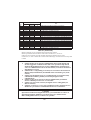
TABLE OF CONTENTS
SECTION 1
1.1
1.2
GENERAL DESCRIPTION
INTRODUCTION .................................................................................................................................... 1
EQUIPMENT FEATURES ...................................................................................................................... 1
SECTION 2
INSTALLATION
2.1
UNPACKING AND INSPECTION ......................................................................................................... 2
2.2
EQUIPMENT SUPPLIED ....................................................................................................................... 2
2.2.1
Optional Accessories ....................................................................................................................... 2
2.3
PLANNING THE INSTALLATION ........................................................................................................ 2
2.3.1
Typical Mounting Methods .............................................................................................................. 3
2.3.2
Flush Mounting ................................................................................................................................ 3
2.4
ELECTRICAL CONNECTIONS ............................................................................................................ 5
2.4.1
DC Power and External Speaker Connections ................................................................................ 5
2.4.2
External Speaker Connections ......................................................................................................... 6
2.4.3
Antenna Connections ....................................................................................................................... 7
2.4.4
Antenna Mounting Suggestions ....................................................................................................... 7
2.4.5
Grounding ........................................................................................................................................ 7
SECTION 3
OPERATIONS
3.1
INTRODUCTION .................................................................................................................................... 8
3.2
CONTROLS AND LCD DISPLAY ......................................................................................................... 8
3.2.1
Controls ........................................................................................................................................... 9
3.2.2
LCD Display .................................................................................................................................. 10
3.3
OPERATING PROCEDURES ............................................................................................................... 11
3.3.1
Turning the Power on .................................................................................................................... 11
3.3.2
The 16 PLUS (priority) Channel ................................................................................................... 12
3.3.3
Channel Memory ........................................................................................................................... 12
3.3.4
Scan Modes ................................................................................................................................... 12
3.3.5
Master Reset .................................................................................................................................. 13
3.3.6
Monitor Mode ................................................................................................................................ 13
iii
SECTION 4
TECHNICAL DESCRIPTION
4.1
GENERAL ............................................................................................................................................. 14
4.2
THE CONTROL SECTION .................................................................................................................. 14
4.3
THE TRANSMITTER/RECEIVER/PLL SECTIONS .......................................................................... 14
4.3.1
PLL (Phase Lock Loop) Circuit ..................................................................................................... 14
4.3.2
Transmitter Circuit ......................................................................................................................... 15
4.3.3
Receiver Circuit ............................................................................................................................. 15
4.4
SPECIFICATIONS ................................................................................................................................ 16
4.4.1
Transmitter ..................................................................................................................................... 16
4.4.2
Receiver ......................................................................................................................................... 16
4.4.3
Operating Requirement .................................................................................................................. 17
4.4.4
Radio Dimensions .......................................................................................................................... 17
4.5
BLOCK DIAGRAM .............................................................................................................................. 18
4.6
Ray48 ASSEMBLY DRAWING ............................................................................................................ 19
SECTION 5
MAINTENANCE
5.1 GENERAL ........................................................................................................................... 21
5.1.1 How to contact Raymarine ........................................................................................... 21
SECTION 6
6.1
Ray48 MARINE CHANNELS AND THEIR USAGE .......................................................................... 23
SECTION 7
7.1
Ray48 MARINE CHANNELS FREQUENCY TABLES
APPENDIX
VHF MARINE CHANNEL USAGE GUIDE
AND LICENSING REQUIREMENTS ................................................................................................. 27
iv
GLOSSARY OF TERMS
VHF ............................................................. Very High Frequency 30MHz to 300MHz
FM ............................................................... Frequency Modulation
Carrier Wave ................................................ A Radio Frequency on which intelligence is superimposed.
Dual Watch .................................................. Monitor channel 16 while working on another channel.
Tri Watch ..................................................... Monitor channel 16 and weather channel while working on another
channel.
All Scan ....................................................... Scans all channels
Memory Scan .............................................. Scans only user selected memory channels
US Channels ................................................ Channel designations as defined by the FCC
International Channel .................................. Channel designator as defined by International Telecommunication
Union
Weather Channels ........................................ Channels for routine and emergency weather information
broadcast by NOAA
NOAA ......................................................... National Oceanographic and Atmospheric Administration
RTCM .......................................................... Radio Technical Commission for Maritime Services
Simplex ........................................................ Transmit and receive on the same frequency
Duplex ......................................................... Transmit and receive on different frequencies
Squelch ........................................................ A circuit that sets the threshold for cutting off the receiver when
the signal is too weak for reception of anything but noise.
LCD ............................................................. Liquid Crystal Display
TX ................................................................ Transmit
RX ............................................................... Receiver
RF ................................................................ Radio Frequency
CPU ............................................................. Central Processing Unit
PLL .............................................................. Phase Locked Loop (A type of frequency Synthesizer)
VCO ............................................................. Voltage Controlled Oscillator
PTT switch ................................................... Microphone Push-To-Talk switch
v
SECTION 1
GENERAL DESCRIPTION
1.1 INTRODUCTION
Congratulations on your purchase of Raymarine's Ray48 marine radiotelephone.
The Ray48 is a CPU-controlled, digitally synthesized, compact transceiver which provides
reliable simplex and half-duplex (two-frequency) communications between ships and from
ships at sea to public or private shore stations. The Ray48 provides two-way
communications on the International and US channels, reception on 10 separate weather
channels, and two-way communications on the International calling and safety channel (16).
This manual describes the physical and functional characteristics of the radiotelephone.
1.2 EQUIPMENT FEATURES
The Ray48 is designed and manufactured to provide ease of operation with excellent
reliability. The important built-in features of the equipment are listed below.
•
•
•
•
•
•
•
•
•
•
Submersible to IPX7 standard
All solid-state circuitry for low current drain and maximum reliability.
Series diode protection on input power circuits to prevent reverse polarity damage
High-performance receiver section with optimum selectivity
54 channel transmit and 93 channel receive capability within the assigned VHF-FM
maritime band.
Exclusive circuit that automatically selects 16/9 (priority) channel when the radio is
turned on.
Exclusive weather alert feature (when in monitor mode).
Selected channel number indicated on the LCD digital display.
Key entries for "Quick" 16 PLUS, and 10 weather channels WX0 through WX9.
All-Scan and Memory Scan features.
1
SECTION 2
INSTALLATION
2.1 UNPACKING AND INSPECTION
Use care when unpacking the unit from the shipping carton to prevent damage to the
contents. It is also good practice to save the carton and the interior packing material. The
original packing material should be used in the unlikely event it is necessary to return the
unit to the factory.
2.2 EQUIPMENT SUPPLIED
The following is a list of materials supplied with the Ray48:
Description
Part No.
Ray48 White
Ray48 Charcoal
E43020
E43021
Handbook
81233
Power/External Speaker Cable
Microphone Bracket for White Radio
G623680-3
R49099
Microphone Bracket for Charcoal Radio
Mounting Yoke for White Radio
R49100
R49101
Mounting Yoke for Charcoal Radio
R49102
Yoke Knob w/Spacer for White Radio
R49094
Yoke Knob w/Spacer for Charcoal Radio
R49096
2.2.1 Optional Accessories
Description
Flush Mount Kit
Part No.
E46034
2.3 PLANNING THE INSTALLATION
When planning the installation for your Ray48, the following conditions should be
considered to insure dependable and trouble-free operation.
•
•
•
•
The mounting location should be easily accessible to allow operation of the front panel.
The radio should be located at least 3 feet from the antenna.
There should be adequate ventilation for the control unit.
A sufficient space should be secured behind the transceiver to allow for proper cable
connections to the rear panel connectors.
2
• The transceiver should be located as near to the power source as possible.
• The selected location should be as far apart as is possible from any devices that
may cause interference such as motors, generators, and other on board electronics.
• Generally speaking, the transceiver should be protected from prolonged direct
exposure to rain and salt spray. It is always a good practice to protect your valuable
electronic equipment as much as possible.
• Use adequately sized wire for all DC power connections and make sure to solder all
in-line connectors or splices.
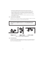
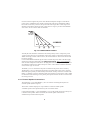
2.3.1 Typical Mounting Methods
The Ray48 can be conveniently mounted on a chart table, bulkhead, overhead, or any other
desired location (refer to Figure 2-1 for typical mounting methods).
CAUTION
Make sure there are no hidden electrical wires or other items behind the desired
location before proceeding. Check that free access for mounting and cabling is
available.
Fig.2-1 TYPICAL MOUNTING METHOD
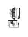
2.3.2 Flush Mounting
In addition to the typical Mounting Methods, the Ray48 may also be flush mounted using
the optional Flush Mount Kit (E46034). This kit is available from Raymarine Customer
Service or your local Raymarine dealer.
3
Fig.2-2 OUTLINE AND MOUNTING DIMENSIONS
All dimensions are shown in (inches) and millimeters
4
195(7.66)
160(6.29)
151(5.94)
19(0.74)
110(4.33)
85(3.03)
120(4.72)
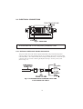
2.4 ELECTRICAL CONNECTIONS
Fig.2-3 REAR VIEW
CAUTION
Do not install this radio on vessels with positive ground battery systems.
2.4.1 DC Power and External Speaker Connections
The power cable comes with external speaker attachments. The power/external speaker
cable provided is 6 feet long and plugs into the 4 pin connector cable at the rear panel of the
radio. The RED (+) wire with an in-line fuse (10 amps) and the BLACK (-) wire of the 4 pin
connector cable are used for connecting the Ray48 to the ship's 12 VDC power system.
(Refer to Fig. 2-4)
Fig.2-4 POWER/EXTERNAL SPEAKER CABLE AND
4 PIN CONNECTOR CABLE
5
In most cases the length of the power cable should be adequate enough to reach the DC
power source. If additional wire length is required, the cable can be extended by adding
more cable as necessary. However, for power cable runs longer than 15 feet, larger wire
diameter size should be used to prevent voltage line loss. Fig 2-5 provides recommended
wire sizes to use for various cable run distances.
Fig.2-5 POWER CABLE LENGTH
Your Ray48 radio should be connected to the nearest primary source of ship's DC power.
A typical source may be a circuit breaker on the power panel or a fuse block near the unit.
When connecting to either of these sources, the circuit breaker or other in-line fuse should
be rated at 10 amps.
It is recommended that terminal lugs be used to connect the power cable to the DC supply
and the lug connections should be both crimped and soldered. This is very important in
order to insure adequate current draw to the equipment. Intermittent operation may result if
an insufficient connection is made to the power source. The connection terminal should be
clean, with no sign of corrosion.
The RED (+) wire is connected to the positive terminal of the power source or battery.
The BLACK (-) wire is connected to the negative (ground) of the power source or battery.
Should the power polarity be inadvertently reversed, the 10 amp. in-line fuse located in the
RED (+) conductor will open. Check the input power leads for correct polarity with a VOM,
reconnect the leads observing correct polarity, and replace the fuse. Be sure to use the same
rate and type of fuse.
2.4.2 External Speaker Connections
The YELLOW (+) wire and GREEN (-) wire are used for connecting the Ray48 to an
external speaker (Refer to Fig.2-4).
Three watts of audio output power is provided for an external 4 ohm speaker.
A suitable speaker can be purchased from your local marine dealer.
Connect the YELLOW (+) wire and GREEN (-) wire to the speaker observing polarity as it
is marked on the speaker. When connected, the external speaker will function
simultaneously with the internal speaker.
6
2.4.3 Antenna Connections
The coaxial cable to your VHF antenna is intended to be connected to the antenna jack on
the rear panel using a PL259 VHF type connector. The antenna cable can be cut to length
but the overall cable length can be critical to performance. If you are uncertain, contact a
professional installer or call our Product Support department. If a longer cable length is
required, RG-58 (50 ohm) coaxial cable or equivalent cable may be used for runs up to a
maximum of 50 feet. If the distance required is even greater, then we recommend using low
loss RG-213 or equivalent cable for the entire run in order to avoid excessive losses in
power output.
If the antenna RF connector is likely to be exposed to the marine environment, a protective
coating of grease (Dow Corning DC-4 or similar) can be applied to the connector before
connecting it to the radio. Any other extensions or adapters in the cable run should also be
protected by silicon grease and then wrapped with a waterproofing tape.
2.4.4 Antenna Mounting Suggestions
The best radio in the world is useless without a quality antenna and good location. Mounting
the VHF antenna properly is very important because it will directly affect the performance
of your VHF radio. A VHF antenna designed for marine vessels should be used.
• Since VHF transmissions are essentially line-of light, mount the antenna where it is free
of obstructions to obtain maximum range.
• If you must extend the length of the coaxial cable between the antenna and the radio, use
a coaxial cable designed for the least amount of power loss over the entire cable length.
• Keep the coaxial cable between the radio and antenna as short as possible but remember
to maintain the recommended 3 feet between the radio and antenna.
Please note that some antennas are supplied with a cable that may not be altered in any way.
Please check the instructions supplied with your antenna before cutting or altering the cable.
2.4.5 Grounding
While special grounding is not generally required for VHF radiotelephone installations, it is
good marine practice to properly ground all electronic equipment to the ship's ground
system. The Ray48 can be connected to ground by attaching a wire to one of the screws on
the unit's rear panel and then to the nearest ship's ground connection point.
The recommended wire to be used for such grounding is #10 AWG.
Fig.2-6 TYPICAL GROUNDING METHODS
7
SECTION 3
OPERATIONS
3.1 INTRODUCTION
Your Ray48 has the capability to transmit and receive on all available US and International
Marine VHF radiotelephone channels. There are channels that are FCC approved but may
only be used by authorized stations for specific purposes, depending on the type of vessel
(commercial or noncommercial). Refer to Table 6-1. This table lists all of the marine VHF
channels available in your Ray48 for US and International radiotelephone use. Full
familiarization of this table is essential when selecting your channels to insure proper
channel usage.
3.2 CONTROLS AND LCD DISPLAY
MIC
16
PLUS
CH
1W SCAN
WX ALT
MON
INT MEM
TX
PWR/VOL
RAY 48 VHF RADIO
16
PLUS
WX
INT
MON
1/25
SCAN
SQ
Fig.3-1 LAYOUT OF CONTROLS AND CONNECTORS
8
3.2.1 Controls
1 VOLUME Control (On/Off)
Turns the radio On and Off and controls the Volume of the audio output to the speaker.
2 [▲] [▼] Keys
The Up and Down keys are used to move the channel numbers up or down. The channel
number can be increased or decreased by one with each key press, or will continue to
increase or decrease the number as the key is held.
3 SQUELCH control
Provides an adjustable input signal threshold to eliminate random RF background noise
during "no signal" conditions. This control sets the signal-to-noise ratio at which a signal
will become audible.
4 [16 PLUS] Key
Used to select channel 16 immediately. This channel has been preset to channel 16 at the
factory prior to shipment. Refer to section 3.3.2 for instructions on how to change the 16
PLUS channel. The 16 PLUS key on the microphone has the same functions as the 16
PLUS key on the radio.
5 [WX/INT] Key
When pressed once, puts the radio into the weather channel receiving mode. A "WX" will
be displayed on the LCD along with the weather channel number (0-9).
When pressed and held for two seconds, the radio toggles between the US and
International channel sets. "INT" appears on the display in International mode.
6 [MON/1/25] Key
When pressed once, the radio enters the MONITOR mode and "MON" is displayed on the
LCD. In this mode, the radio will scan (monitor) 16 PLUS (priority) channel,
a selected working channel, and a weather channel for the weather alert tone.
When pressed and held for two seconds, this key toggles the transmitter output power
between 1 watt ("1W" is displayed) and 25 watts ("1W" disappears).
7 [SCAN] Key
Used to enter All Scan and Memory Scan Modes.
More detailed operation information is available in Section 3.3.4 Scan Modes
8 PTT (Push-To-Talk) Switch
When pressed, puts the radio into the transmit mode and "TX" will be displayed on the
LCD.
9 [▲] [▼] Keys
The Up and Down keys are used to move the channel numbers up or down. The channel
number can be increased or decreased by one with each key press, or will continue to
increase or decrease the number as the key is held.
[16 PLUS] Key
Used to select channel 16 immediately. This channel has been preset to channel 16 at the
factory prior to shipment. Refer to section 3.3.2 for instructions on how to change the 16
PLUS channel. The 16 PLUS key on the microphone has the same functions as the 16
PLUS key on the radio.
All of the above keys except PTT will produce an audible “beep” when pressed.
9
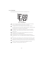
3.2.2 LCD Display
The following describes the functional characters on the Ray48's LCD.
1W SCAN
WX ALT
MON
INT MEM
TX
Fig.3-2 LCD DISPLAY
1
SCAN: Will flash by itself when All-Scan mode is to be initiated or will flash in
unison with "MEM" when Memory Scan mode is to be initiated.
2
1 W (High/Low Power): Will be displayed when the transmitter circuits are
providing 1 Watt of power to the antenna. When the transmitter is supplying 25 Watts
to the antenna, the "1 W" indication will be extinguished.
3
ALT (Weather Alert): Will blink when a Weather Alert Tone has been detected.
4
WX (Weather): Will be displayed when the channel selected to be monitored is a
weather channel.
5
MON (Monitor): Will be displayed when the MON/INT key is pressed. This
indicates the radio is in the MONITOR mode.
6
INT (International/USA): Will be displayed when International channels are
programmed for use. "INT" is not displayed when US channels are programmed for
use.
7
TX (Transmit): Will be displayed on the LCD when the Push-To-Talk (PTT) switch
is depressed indicating the transmitter circuits are providing a signal to the antenna.
8
MEM (Memory): Will be displayed when the SCAN key is pressed and held for two
seconds, or when the radio is programmed to the MEMORY SCAN mode.
9
LCD Segments: Will display channel number in use.
10
3.3 OPERATING PROCEDURES
3.3.1 Turning the Power On
1)
Rotate the ON/OFF/VOLUME control clockwise to turn the radio on.
NOTE
When the Power is on, the synthesizer automatically programs for the USA channel
frequencies and selects the calling channel 16. (Refer to 16 PLUS operation to
change this channel.)
Setting the Volume
1)
2)
Rotate the SQUELCH control slowly counterclockwise. Background noise will be
heard.
Rotate the VOLUME control for the desired volume level.
Setting the Squelch
1)
Rotate the SQUELCH control slowly clockwise until the background noise ceases.
Setting the Power Output
1)
Press the "MON/1/25" key for two seconds to toggle between 1 Watt output and 25
Watt output. When "1 W" is displayed, the output power is 1 watt.
If "1 W" is extinguished, 25 watts is being output. The choice of power output is
dependent upon the distance of transmission and transmitting conditions.
In certain US harbors and on certain channels, the FCC requires the power to be
limited to 1 watt. On these "required" channels, the radio automatically selects the 1
Watt power output when the channel is selected.
NOTE
Channels 13 and 67 are restricted to 1 Watt operation but may be overridden in
emergencies. To obtain 25 Watt output on these channels, while in transmit mode
(pressing the PTT switch), press and hold the MON/1/25 key. As long as the MON/1/
25 key is held, power output will be 25 Watts. When the key is released, the radio
reverts back to 1 Watt as indicated on the LCD.
Selecting the Channel
1)
To select the appropriate channel, press the [▲] or [▼] channel select keys. Refer to
Table 6-1 to select your "working" channel.
To Transmit
1)
2)
Select the desired mode (INT or USA) by pressing and holding the WX/INT key for
two seconds. When "INT" is displayed, International mode is selected. When
extinguished, USA mode is active. Then press the Push-To-Talk switch and speak into
the microphone using a clear normal voice.
When the power is initially turned on, press the Push-To-Talk switch, the radio will be
ready for transmission on CH 16 or a user selected priority channel (16 PLUS).
As a safety feature, the Ray48 is designed to inhibit transmission if the Push-to-Talk switch
is pressed continuously for over five minutes. If this occurs, audible beeps will sound and
"TO" (time out) blinks on the LCD until the Push-To-Talk switch is released. After releasing
the Push-To-Talk switch, the radio is ready for reception.
11
NOTE
Initial communication contacts are usually made over channel 16 as all ships and shore
stations monitor this channel. Then a shift to a working channel will be necessary.
To Select a Weather Channel
1)
2)
Press the WX/INT key, then use the Up [▲] or Down [▼] key to select the desired
weather channel from 0 to 9. When this mode is selected, the transmitter is always
inhibited.
If a weather alert signal is received on your selected WX channel (when in the Monitor
Mode) there is a five-second audible alarm generated. To cancel the audible alarm,
press any key.
3.3.2 The 16 PLUS (priority) Channel
The 16 PLUS channel has been preset to channel 16 prior to shipment from the factory, but
the 16 PLUS channel can be changed to another number, with the exception of all weather
channels.
1)
2)
Press the Up [▲] or Down [▼] key to select the desired channel. Then press and hold
the 16 PLUS key for three seconds. An audible beep tone will confirm that the selected
channel is stored in memory as the 16 PLUS channel.
To reselect channel 16 as the 16 PLUS channel, repeat step 1 for channel 16.
3.3.3 Channel Memory
The Ray48 can store into memory all U.S. or International channels. The stored channels
will be scanned during Memory Scan mode.
1)
2)
Channel Memory: To put a channel into memory, select the channel to be stored with
the Up or Down arrows. Push and hold the "SCAN" key for approximately two
seconds until a "beep" is heard and "MEM" is displayed on the LCD. This procedure
can be repeated for all U.S. or International channels.
Memory Clear: To clear a channel from memory, select the channel to be cleared with
the Up or Down arrows. Push and hold the "SCAN" key for approximately two
seconds until a "beep" is heard and "MEM" disappears from the LCD.
3.3.4 Scan Modes
The Ray48 is equipped with two types of scan options, All-Scan and Memory Scan. How
these options are accessed is dependent upon whether there are any channels stored in
memory.
1)
All-Scan mode
If no channels are stored in memory, when the SCAN key is pressed once, "SCAN"
will begin to flash on the LCD. In three seconds, if no other keys are pressed, the radio
will begin scanning all channels (except weather channels) as long as no signal is
received. If a signal is received, the scan will stop and monitor the receiving channel.
If the signal is lost for five seconds, the radio will resume scanning. If the scan has
stopped on a received signal, you may resume scanning by pressing the SCAN key.
To cancel the scan mode, press the SCAN key once while the radio is scanning.
12
2)
Memory Scan Mode
If one or more channels are stored in memory, when the SCAN key is pressed,
"SCAN" and "MEM" will begin to flash simultaneously on the LCD. If no other key is
pressed, the radio will begin scanning all channels currently in memory in three
seconds. As with All-Scan, if a signal is received, the scan will stop on the receiving
channel until the signal is lost for five seconds or the SCAN key is pressed. To cancel
memory scan, press the SCAN key while the radio is scanning.
If you have one or more channels in memory and want to initiate All-Scan, perform
the following:
Press the SCAN key. "SCAN" and "MEM" will flash on the LCD. Press the SCAN key
again within three seconds and "MEM" will disappear from the LCD leaving only "SCAN"
flashing. All-Scan will begin in three seconds if no other key is pressed.
3.3.5 Master Reset
To perform a master reset, press and hold the 16 PLUS key while turning the unit on.
This feature clears all channels from memory and programs the 16 PLUS feature back to
channel 16.
3.3.6 Monitor Mode
Before entering the Monitor Mode you must first select the WX channel you wish to
monitor for the weather alert tone. Next, you must also select a working channel to be
monitored for traffic. (Refer to section 3.3 for instruction on channel section).
1) Press WX/INT, then scroll to the desired weather channel with the arrow keys.
2) Press the 16 PLUS key to exit the weather band and return to normal mode.
3) Use the arrow keys to select the desired working channel.
4) Press the MON/1/25 key to begin monitor mode. Press the MON/1/25 key again to
cancel Monitor Mode.
As an example, let's say we have selected channel 68 as our working channel, WX2 as our
weather channel and the 16 PLUS key is programmed for channel 16.
When MON/1/25 is pressed, the radio begins to scan Priority Channel 16, the working
channel 68 and weather channel WX2.
Working Channel
If a signal is received on CH68, the scan will stop on CH68, but continue to monitor 16
PLUS and the selected weather channel every five seconds.
16 PLUS (priority) Channel
If while scanning, a signal is received on the designated 16 PLUS channel, the scanning will
stop on 16 PLUS as long as the signal is being received. If the signal ceases for more than
five seconds, the scanning will continue.
Weather Channel
Until a weather alert tone signal is received on WX2, the scan will stop on WX2 briefly, but
will not give any audio output. When a weather alert tone (1050Hz) is received, the monitor
will stop and an audible alarm will sound. When the audio alert ends in five seconds, the
emergency weather broadcast will be heard. To silence the alarm, simply push any key.
13
SECTION 4
TECHNICAL DESCRIPTION
4.1 GENERAL
The Ray48 can be considered as consisting of two major sections. They are:
• The Control Circuitry (considering of the front panel controls, the LCD display,
control CPU)
• The Transmitter/Receiver/PLL circuits
4.2 THE CONTROL SECTION
The heart of the control section is the CPU IC201, located on the Front PCB.
The CPU controls all of the following items:
• Controls the Squelch circuit by detecting a busy signal from the second IF circuit IC5.
• Generates a beep tone when a key is activated on the keyboard.
• Mutes the transmitter modulation circuit when receiving.
• Controls the output power of the transmitter High/Low.
• Controls the dividing ratio N of the PLL circuit.
• Switches On/Off the transmitter power.
• Mutes AF audio.
• Detects a weather alert signal (when in Monitor Mode).
• Controls the LCD display.
4.3 THE TRANSMITTER/RECEIVER/PLL SECTIONS
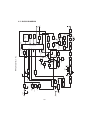
In reading through the following circuit descriptions, it may be helpful to refer to Figure 4-1
Block Diagram of the TX/RX/PLL circuits.
4.3.1 PLL (Phase Lock Loop Circuit)
The PLL circuit is the frequency synthesizer in the Ray48.
The reference frequency of 12.8 MHz is provided by crystal XTL1 and IC3. IC3 contains
the reference oscillator (12.8 MHz) circuit, the phase comparator, the program counter and
the phase detector. The 12.8 MHz reference signal is divided by 512 in the program counter
in IC3 to obtain a 25 KHz reference signal. The dividing ratio is determined by CPU IC201.
The VCO output from oscillator Q4 is amplified by buffer amplifier Q3, and returned to IC3
and is divided by the dividing ratio N to obtain a 25 KHz signal. N for 1N in IC3 is
determined by CPU IC201. Both of these 25 KHz signals are fed into the phase comparator
circuit of IC3.
The phase detected signal, obtained by comparing the two 25 KHz signals the same phase.
When this condition is met, the PLL circuit is locked. If the two signals have a large phase
difference, the PLL is unlocked. In this condition, the unlocked signal is fed to CPU IC201
from IC3 and the transmitter is compelled to stop.
The VCO output from Q4 is fed to the TX amplifier Q2 and the first RX mixer Q19 through
buffer amplifier Q3.
14
4.3.2 Transmitter Circuit
A signal from the microphone is fed to a pre-emphasis operations amplifier IC3, and
modulates VCO (Q4) through active LPF IC2.
The VCO output signal from Q4 is sent to the RF power amplifiers IC1, Q1 and Q2 through
buffer amplifier Q3. The RF signal from IC1 is fed to the antenna through a low pass filter.
The DC voltage correlative to the RF output is detected by D2 and Q9, amplified by Q24
and fed to IC1. The output power voltage from IC1 controls the RF power to keep RF
output at a constant level.
4.3.3 Receiver Circuit
1)
RF Circuit
The signal from the antenna passes through the single tuned band pass filter, and is
amplified by RF amplifier Q17, and is fed into a triple tuned band pass filter. The
signal is then mixed by Q19 (first mixer) and produces the first IF signal of 21.6 MHz.
This signal is sent to a crystal filter (21.6 MHz) and first IF amplifier Q20, mixed by
IC4, the second mixer, and becomes an audio signal after detection.
2)
IF Circuit
The output of the first IF amplifier Q20 is fed into IC4. IC4 contains the second mixer,
second local oscillator, 455 KHz amplifier, quadrature detector and DC switching
amplifier.
A 455 KHz ceramic filter is installed between pins 3 and 5 of IC4 to examine the
selectivity of this unit.
The detector output is separated into audio and noise components by an RC filter.
The noise component is fed back to the noise amplifier section of IC4. Its output is
rectified by a diode in IC4 and then fed to the switching amplifier in IC4.
3)
AF Circuit
The signal from IC4 is amplified by IC5 to drive the speaker while the receiver is in
the squelched condition. Muting control of IC5 is carried out by the CPU IC201.
4)
Weather Alert Tone Detecting Circuit
If a weather alert tone is included in the AF signal from IC4 while receiving the
weather service broadcast, IC6 detects it and notifies an alert condition to CPU IC201.
15
4.4 SPECIFICATIONS
4.4.1 Transmitter
Channels
Frequency Stability
Frequency Range
Channel Spacing
Power Output
modulation
Modulation Audio Response
FM Hum & Noise Level
Audio distortion
Spurious & harmonic Emissions
Antenna Impedance
Transmitter Protection
53 US/International
±10PPM (±0.001%)
(-20°C to +50°C)
156.025 to 157.425 MHz
25 KHz Increments
25 Watts switchable to 1 Watt into 50 Ohms at
13.6 Vdc
Frequency modulated 16F3
(±4.5 KHz at 1000 Hz)
Shall not vary +1/-3 dB from true 6 dB pre-emphasis
from 300 to 2500 Hz, reference 1000 Hz. Audio
frequences 3-20 KHz shall be attenuated (at 1KHz by
60 log f/3 dB. Above 20 KHz by 50 dB)
Greater than -40 dB below audio
Less than 10% at 1 KHz for ±3 KHz deviation
Attenuated at least 43+10 log Po (below rated
radiated carrier power) per FCC Rules Parts 2 & 80
50 Ohms
Shall survive open or short circuit of antenna
system without damage (10 min. test)
4.4.2 Receiver
Channels
Frequency Range
Frequency Stability
Usable Sensitivity
Squelch Sensitivity Threshold
Adjacent Chl Rejection
Spurious Image Rejection
Intermodulation Rejection
Audio Output
Hum & Noise in Audio
93 (includes 10 weather channels)
156.025 to 163.275 MHz in 25 KHz increments
±10 PPM (±0.001%) from -20°C to +50°C
0.3µV for 12 dB (SINAD)
0.2µV or better
1.0µV full squelch
Greater than 65 dB
Greater than 65 dB
Greater than 65 dB
3 Watt or more at 10% or less distortion into 4 Ohm
load
Less than -40 dB
16
4.4.3 Operating Requirement
Input Voltage
Current Required Transmit
Operating Temperature
Duty Cycle
Humidity
13.6 Vdc ±15% (11.6 to 15.6 Vdc)
Less than 5.8 amp at 25 Watts
Less than 1.5 amp at 1 Watt
-20°C to +50°C
Continuous, 80% receive, 20% transmit
(max 10 min. @25°C)
100% at 50°C for 8 hours
4.4.4 Radio Dimensions
Height
Width
Depth
Weight
70mm
160mm
120mm
900g (1.98 lbs)
17
4.5 BLOCK DIAGRAM
MIC/PTT
UP/ON
LPF
ANT
SW
D1 MI402
D4 MI308
BPF
TX ON1
PRE
DRIVE
Q2 2SC4226
1st MIX
Q19 2SK506
Q3 2SC4226
1Pole
Xtal FIL
21.6MHz
+SV
DC
FIL
Q20 2SC3123
1st IF AMP
BAND
SW
Q6 DTC114KE
Q5
2SC4116
POV
D7
KV1832C
D8 ISS226
FIL
TX-B
SW
Q2 DTC114EK
Q7
2SA211A
SW
SW
Q15 DTC114EK
VCO
Q4
2SK508
MOD
DC
CONT
ADT
DRIVE
Q1 2SC3357
RF AMP
Q17 2SC4226
D12 1SS226 BPF
BPF
IC1 S-AV6
POWER
MODULE
13.6V Y
1W
D6
ISV214
PWR
DET
Q2 1SS345
BUFF
AMP
13.6V Z
Q7 2SB1135
Q10 2SC4116
Q24 2SC4116
Q11 DTC114EK
25W
ADJ
UN LOCK
Q23 DTC114EK
TXON2
SW
12.8MHz
PLL
IC3
LC7153M
SW
LPE
DATA
CK
CE
BUST
DEEP TONE Q202
DTC114EKT
UN LOCK
TONE DET
MUTE1
MUTE2
TX ON
SV
RESET
IC203
RHSVA45AA1
XTAL202
32.768KHE
TX-B
-SdB/dct
"SQ"
AF
AMP
Q12 2SC4116
BUFF
AMP
Q22 2SC4116
+5V
REG
INT SP
EXT SP
DC13.6V
D11
FMBG24
13.6V Y
RX-B
SV
D7 DAN202K
TX-B
SV
DEEP TONE
13.6V Z
Q13 2SA1298
SW
SW
SW
Q14 DTA124EK
Q21
DTC343
SP AMP
ICS LA4425
TONE
DET
"VOL"
TX ON1
SV
MUTE1
TC6 BA1604F
SW
Q12 2SA1298
RX-B
SW
TX ON2
Q3 DAN202K
SV
D10 DAN202K
ISOLATER
BPF
445KHz
2nd MIX IF AMP
IC4 TA31136F
21.145MHz
Fig. 4-1 Ray48 Block Diagram
18
IC2 2902M
"DEV"
PWR LO
PTT DET
UP/ON
PRE⋅ENPH
& LIMITER
SW
Q201 2SA1292
E2PROM
IC202 93LC46X
KEY
BOARD
LCD
DISPLAY
XTAL201
1.2MHE
IC201 M34520 M6
4.6 Ray48 ASSEMBLY DRAWING
24
26
35
23
29
22
3
25
5
33
21
8. KNOB SQUELCH
19
7
34
18
17
2
32
20
13
14
31
27
4
16
15
12
11
30
1
10
8
9
6
1.
2.
3.
4.
5.
6.
FRONT PANEL ASSEMBLY
MID COVER ASSEMBLY
REAR COVER
FRONT GASKET
REAR GASKET
FRONT PCB ASSEMBLY
7. MAIN PCB ASSEMBLY
28
9. KNOB POWER/VOLUME
10. POWER/VOLUME/SQUELCH
POT NUT
11. O-RING (m6)
12. POWER/VOLUME/SQUELCH
PCB ASSEMBLY
13. KEY MAIN
14. KEY CH
15. HOLDER - KEY MAIN
16. HOLDER - KEY CH
17. INTERNAL SPEAKER
18. HOLDER SPEAKER
19. PLATE SPRING
20. TERMINAL GROUND
21. GASKET (ANT) 20mm
22. ANTENNA RF CONNECT
23. O-RING (m9)
24. POWER CORD ASSEMBLY
25. MICROPHONE ASSEMBLY
26. MIC HANGER KIT
27. YOKE KNOB KIT
28. MOUNTING YOKE KIT
29. O-RING (m2.6)
30. SCREW m2.6X8
31. SCREW m2.6X5
32. SCREW HEXAGON M2.6
33. SCREW M2.6X12
34. SCREW M3X8
35. SCREW M2.6X12TP
36. SCREW M5X20TP
19
20
SECTION 5
MAINTENANCE
5.1 GENERAL
The Ray48 is designed to provide long periods of trouble-free operation. It is
recognized, however, that environmental and other factors may result in a need for
occasional service.
5.1.1 How to contact Raymarine
Technical Support: 1-800-539-5539 ext. 2444 or 603-881-5200 ext. 2444
You may reach our Technical Support Department Monday to Friday 4:00 AM to 6:00
PM Eastern Time. Our Technical Support Specialists are available to answer installation,
operation, and trouble-shooting questions about your Raymarine unit.
Accessories and Parts: 1-800-539-5539 ext. 2333 or 603-881-5200 ext. 2333
Many Raymarine accessory items and parts are available through your authorized
Raymarine dealer. However if you are in need of an item not available through your
retailer feel free to contact our Customer Service department Monday to Friday 8:15
AM to 5:00 PM Eastern Standard Time. If you are uncertain about what item to
choose for your Raymarine unit please contact our Technical Support Department Prior
to placing your order at 603-881-5200 ext. 2065.
Product Repair and Service
In the unlikely event your Raymarine unit should develop a problem please contact the
Raymarine dealer from where the unit was purchased. Your Raymarine dealer is best
equipped to handle your service needs.
Service may also obtained by returning your unit to Raymarine's Product Repair Center at
the address below.
Raymarine, Inc.
Product Repair Center
22 Cotton Road, Unit D
Nashua, NH 03063-4219
21
On the Internet
Visit the Raymarine World Wide Web site for the latest information on Raymarine electronic
equipment and systems at:
www.raymarine.com
Navigate to the Customer Support Page, which provides links for:
•
•
•
•
•
Finding Factory Service locations and Authorized Dealers near you
Registering your Raymarine products
Accessing handbooks in Adobe Acrobat format
Downloading RayTech software updates
Accessing the Raymarine solution database
Clicking the Find Answers link routes you to our solution database. Search questions and
answers by product, category, keywords, or phrases. If the answer you are seeking is not
available, click the Ask Raymarine tab to submit your own question to our technical
support staff , who reply to you by e-mail.
22
SECTION 6
Ray48 MARINE CHANNELS FREQUENCY TABLES
6.1 Ray48 MARINE CHANNELS AND THEIR USAGE
CAUTION
The transmitter of the Ray48 is disabled when channel 15, 75, 76 or WX0-WX9 is
displayed.
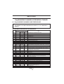
U.S. VHF Marine Radio Channels and Frequencies
CH
No.
Frequency
01A
XMIT
--
156.050
Single
x
02
03
04
05A
---156.250
156.100
156.150
156.200
156.250
x
x
x
x
06
07A
08
09
10
11
12
13
156.300
156.350
156.400
156.450
156.500
156.550
156.600
156.650
156.300
156.350
156.400
156.450
156.500
156.550
156.600
156.650
x
x
x
x
x
x
x
x
14
15
16
156.700
-156.800
156.700
156.750
156.800
x
x
x
17
18A
19A
20A
21A
22A
156.850
156.900
156.950
157.000
157.050
157.100
156.850
156.900
156.950
157.000
157.050
157.100
x
x
x
x
x
x
23A
24
25
26
27
28
60
61
62
63A
157.150
157.200
157.250
157.300
157.350
157.400
156.025
156.075
156.125
156.175
157.150
161.800
161.850
161.900
161.950
162.000
156.025
156.075
156.125
156.175
x
64
65A
156.225
156.275
156.225
156.275
x
x
RCV
x
x
x
x
Use
Port Operations and Commercial, VTS.
Available only in New Orleans/Lower Mississippi area.1
Port Operations
Port Operations
Port Operations
Port Operations or VTS in the Houston, New Orleans and
Seattle areas.
Intership Safety
Commercial
Commercial (Intership only)
Boater Calling. Commercial and Non-Commercial
Commercial
Commercial. VTS in selected areas.
Port Operations. VTS in selected areas.
Intership Navigation Safety (Bridge-to-bridge). Ships 20 meters in
length maintain a listening watch on this channel in US waters.2,4
Port Operations. VTS in selected areas.
Environmental (Receive only). Used by Class ’C’EPIRBs
International Distress, Safety and Calling. Ships required to
carry radio, USCG, and most coast stations maintain a
listenitng watch on this channel. 3
State Control
Commercial
Commercial
Port Operations
U.S. Coast Guard only
Coast Guard Liaison and Maritime Safety Information
Broadcasts. Broadcasts announced on channel 16.
U.S. Coast Guard only
Public Correspondence (Marine Operator)
Public Correspondence (Marine Operator)
Public Correspondence (Marine Operator)
Public Correspondence (Marine Operator)
Public Correspondence (Marine Operator)
Port Operations
Port Operations
Port Operations
Port Operations and Commercial, VTS. Available only in New
Orleans/Lower Mississippi area.
Port Operations
Port Operations
Table 6-1
23
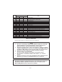
Frequency
CH
No.
XMIT
RCV
66A
67
156.325
156.375
156.325
156.375
68
69
70
71
72
73
74
75
76
77
78A
79A
80A
81A
82A
83A
84
85
86
87
88A
156.425
156.475
156.525
156.575
156.625
156.675
156.725
--156.875
156.925
156.975
157.025
157.075
157.125
157.175
157.225
157.275
157.325
157.375
157.425
156.425
156.475
156.525
156.575
156.625
156.675
156.725
156.775
156.825
156.875
156.925
156.975
157.025
157.075
157.125
157.175
161.825
161.875
161.925
161.975
157.425
Single
x
x
x
x
x
x
x
x
x
x
x
x
x
x
x
x
x
x
x
Use
Port Operations
Commercial. Used for Bridge-to-bridge communications in
lower Mississippi River. Intership only. 4
Non-Commercial
Non-Commercial
Digital Selective Calling (voice communications not allowed)
Non-Commercial
Non-Commercial (Intership only)
Port Operations
Port Operations
CH 16 Guard Band. RX only.
CH 16 Guard Band. RX only.
Port Operations (Intership only)
Non-Commercial
Commercial. Non-Commercial in Great Lakes only.
Commercial. Non-Commercial in Great Lakes only.
U.S. Government only - Environmental protection operations.
U.S. Government only
U.S. Government only
Public Correspondence (Marine Operator)
Public Correspondence (Marine Operator)
Public Correspondence (Marine Operator)
Public Correspondence (Marine Operator)
Commercial, Intership only
Table 6-1 (Continued)
Boaters should normally use channels listed as Non-Commercial.
1.
2.
3.
4.
5.
6.
NOTE
The letter “A” following a channel number indicates simplex use of the ship
station transmit side of an international duplex channel. Operations are
different from that of international operations on that channel.
Channels 13 should be used to contact a ship when there is danger of collision.
All ships of length 20 meters or greater are required to guard VHF channel 13,
in addition to VHF channel 16, when operating within U.S. territorial waters.
Channel 16 is used for calling other stations or for distress alerting.
Channel 13 and 67 are 1 Watt initially.
User can override to high power (25 Watts) via front panel controls.
The transmitter is automatically disabled when channels 1, 2, 3 and 4 are
selected.
Channels 75 and 76 are receive-only. Transmission on these channels has been
disabled as a precaution to avoid harmful interference to channel 16.
CAUTION
Operation on channels not designated for use by your classification of craft or on
International Channels within the US territorial waters is a violation of FCC
Rules and Regulations and way result in severe penalties.
24
U.S. NOAA Weather Radio Frequencies
Weather
Channel
Frequency
in MHz
WX0
WX1
WX2
WX3
WX4
WX5
WX6
WX7
WX8
WX9
163.275
162.550
162.400
162.475
162.425
162.450
162.500
162.525
161.650
161.775
International VHF Marine Radio Channels & Frequencies
Frequency
CH
No.
XMIT
01
02
03
04
05
06
07
08
09
10
11
12
13
14
15
16
17
18
19
20
21
22
23
24
25
26
27
28
60
61
62
63
64
65
66
67
68
69
156.050
156.100
156.150
156.200
156.250
156.300
156.350
156.400
156.450
156.500
156.550
156.600
156.650
156.700
-156.800
156.850
156.900
156.950
157.000
157.050
157.100
157.150
157.200
157.250
157.300
157.350
157.400
156.025
156.075
156.125
156.175
156.225
156.275
156.325
156.375
156.425
156.475
RCV
160.650
160.700
160.750
160.800
160.850
156.300
160.950
156.400
156.450
156.500
156.550
156.600
156.650
156.700
156.750
156.800
156.850
161.500
161.550
161.600
161.650
161.700
161.750
161.800
161.850
161.900
161.950
162.000
160.625
160.675
160.725
160.775
160.825
160.875
160.925
156.375
156.425
156.475
Use
Single
x
x
x
x
x
x
x
x
x
x
x
x
x
x
Public Correspondence, Port Operations and Ship Movement
Public Correspondence, Port Operations and Ship Movement
Public Correspondence, Port Operations and Ship Movement
Public Correspondence, Port Operations and Ship Movement
Public Correspondence, Port Operations and Ship Movement
Intership 1
Public Correspondence, Port Operations and Ship Movement
Intership
Intership, Port Operations and Ship Movement
Intership, Port Operations and Ship Movement 2
Port Operations and Ship Movement
Port Operations and Ship Movement
Intership Safety, Port Operations and Ship Movement 3
Port Operations and Ship Movement
Receive Only
Distress, Safety and Calling
Intership and On-board Communications at 1W only 4
Public Correspondence
Public Correspondence, Port Operations and Ship Movement
Public Correspondence, Port Operations and Ship Movement
Public Correspondence, Port Operations and Ship Movement
Public Correspondence, Port Operations and Ship Movement
Public Correspondence, Port Operations and Ship Movement
Public Correspondence, Port Operations and Ship Movement
Public Correspondence, Port Operations and Ship Movement
Public Correspondence, Port Operations and Ship Movement
Public Correspondence, Port Operations and Ship Movement
Public Correspondence, Port Operations and Ship Movement
Public Correspondence, Port Operations and Ship Movement
Public Correspondence, Port Operations and Ship Movement
Public Correspondence, Port Operations and Ship Movement
Public Correspondence, Port Operations and Ship Movement
Public Correspondence, Port Operations and Ship Movement
Public Correspondence, Port Operations and Ship Movement
Public Correspondence, Port Operations and Ship Movement
Intership, Port Operations and Ship Movement
Port Operations and Ship Movement
Port Operations and Ship Movement
Table 6-1 (Continued)
25
Frequency
CH
No.
XMIT
70
71
72
73
74
75
76
77
78
79
80
81
82
83
84
85
86
87
88
-156.575
156.625
156.675
156.725
--156.875
156.925
156.975
157.025
157.075
157.125
157.175
157.225
157.275
157.325
157.375
157.425
RCV
156.525
156.575
156.625
156.675
156.725
156.775
156.825
156.875
161.525
161.575
161.625
161.675
161.725
161.775
161.825
161.875
161.925
161.975
162.025
Use
Single
x
x
x
x
x
x
x
x
Digital Selective Calling for Distress and Safety 5
Port Operations and Ship Movement
Intership
Intership 2
Port Operations and Ship Movement
See Note 6
See Note 6
Intership
Public Correspondence, Port Operations and Ship Movement
Public Correspondence, Port Operations and Ship Movement
Public Correspondence, Port Operations and Ship Movement
Public Correspondence, Port Operations and Ship Movement
Public Correspondence, Port Operations and Ship Movement
Public Correspondence, Port Operations and Ship Movement
Public Correspondence, Port Operations and Ship Movement
Public Correspondence, Port Operations and Ship Movement
Public Correspondence, Port Operations and Ship Movement
Port Operations and Ship Movement
Port Operations and Ship Movement
Table 6-1 (Continued)
Intership channels are for communications between ship stations.
Intership communications should be restricted to Channels 6, 8, 72 and 77.
If these are not available, the other channels marked for Intership may be used.
Channels 10, 67 and 73 should be avoided within VHF range of coastal areas in Europe and
Canada.
1.
2.
3.
4.
5.
6.
NOTES
Channel 06 may also be used for communications between ship stations and
aircraft engaged in coordinated search and rescue operations. Ship stations
should avoid harmful interference to such communications on channel 06 as
well as to communications between aircraft stations, ice breakers and assisted
ships during ice seasons.
Channels 10 or 73 (depending on location) are also used for the broadcast of
Marine Safety Information by the Maritime and Coast Guard Agency in the
UK only.
Channel 13 is designated for use on a worldwide basis as a navigation safety
communication channel, primarily for intership navigation safety
communications.
Channel 17 may also be used for on-board communications provided the
effective radiated power does not exceed 1 Watt.
Channel 70 is to be used exclusively for digital selective calling (DSC) for
distress and safety.
Channels 75 and 76 are receive-only. Transmission on these channels has bees
disabled as a precaution to avoid harmful interference to Channel 16.
CAUTION
Operation on channels not designated for use by your classification of craft or on
International Channels within the US territorial waters is a violation of FCC
Rules and Regulations and way result in severe penalties.
26
SECTION 7
APPENDIX
7.1 VHF MARINE CHANNEL USAGE GUIDE AND LICENSING
REQUIREMENTS
Marine VHF radio users in the US must comply with all applicable FCC rules and
regulations, some of which are described here. This information was current at the time this
book was printed. Up-to-date information, including licensing requirements, can be obtained
on the FCC website at: www.fcc.gov/wtb/marine.
REMEMBER:
• Maintain a radio watch on Channel 16. Channel 16 is used for distress and safety
purposes only.
• Your VHF transceiver has a high low power switch. Use low power whenever feasible.
Unnecessary high-power operations can interfere with other important communications.
• Always use your radio call sign at the beginning and end of each transmission.
• Be sure only qualified persons operate your radio. You are responsible for control of
your radio. Know the rules.
• Limit calls to other vessels to 30 seconds. If you receive no reply, wait 2 minutes; then
try again. Keep communications brief and avoid chit-chat.
• Never transmit false distress messages, and never use profanity on the air.
OTHER REMINDERS:
• You can obtain a station license and call sign by completing FCC Form 605, which is
available on-line at www.fcc.gov/wtb/marine.
You need a radio operator license to operate a VHF Marine Radio only if you plan to dock
in a foreign port or leave a foreign port to dock in a U.S. port.
• Your radio license is not transferable. If you sell your boat, request the FCC to cancel
your station license.
If you replace your radio, you do not need to change your license unless the new radio
operates on another frequency band. If you install equipment to operate on another
frequency band, apply for modification of your license.
• If you carry more than six passengers for hire, your vessel must be certified as a
passenger-carrying vessel by the FCC and the Coast Guard.
Licensing Requirements for Hand Held Portable VHF Marine Transceivers 10 Watts
Power or Less
27
All transceivers, hand-helds included, operated in the Maritime Radio Services are required
to be operated under an appropriate maritime station license. Operation of hand held VHF
Marine transceivers without proper station license can lead to fines and/or administrative
sanctions issued against its user and/or owner.
VHF Marine hand held transceivers can be operated and licensed as follows:
a)
Associated Ship Unit: A hand held VHF Marine transceiver can be operated under an
existing valid ship station license under the following conditions only:
i) Except for safety purposes, the hand held transceivers must be used only to
communicate with the ship station with which it is associated. Such associated ship
units MAY NOT be operated from shore.
ii) The transmitting power is limited to ONE WATT only.
iii) The hand held transceiver must be identified by the call sign of the ship station
along with its associated unit designator.
b)
Portable Ship Station: The Commission may grant a station license permitting
operation of a portable ship station aboard different vessels of the United States.
Each application for a portable ship station license must include a showing that:
i) The station will be operated aboard vessel.
ii) A station license for portable equipment is necessary to eliminate separate
applications to operate a ship station aboard different vessels.
c)
Marine Utility Station: A utility station in the maritime mobile service consists of one
or more hand held transceiver units licensed under a single authorization. Each unit is
capable of operating while being hand carried by an individual. There are two types of
stations authorized:
i) Marine Utility Coast - when transmitters are located on land; may communicate
directly to vessel only.
ii) Marine Utility Coast/Ship - transmitters from land may communicate with vessels
or when aboard a vessel, may communicate with other vessels or coast stations.
NOTE: A Marine Utility Ship license will not be authorized.
The station operates under the rules applicable to a private coast station when the unit(s) are
on land and under the rules applicable to a ship station when the unit(s) are aboard a vessel.
28
USAGE GUIDE
Emergency
Calling
Monitoring
Intership Safety
U.S. Coast Guard
Navigation
Port Operation
Noncommercial
Commercial
Marine Operator
State Control
Environmental
Weather
29
Emergency
Calling
Channel 16
Channel 16 & Working Channel
If:
• Your ship is sinking, or on fire
• Someone has been lost overboard
• There exists grave and imminent
danger
If
- you wish to establish
communications with another
station
And
- you know which working channel
the station is monitoring
Then
- initiate the call directly on that
working channel
If
- you wish to establish
communications with another
station
And
- you do not know what working
channel the station may be
monitoring
Then
- initiate the call on channel 16.
After contact is made switch to a
working channel.
Use this distress procedure:
• Select Channel 16
• Say "Mayday, Mayday, Mayday."
• Give call sign and boat name
• Give location of boat
• Describe emergency
• If no answer, repeat; then try another
channel
Caution
Every ship at sea is to obliged to give
absolute priority to radio
communications relating to ships in
distress - it is vital that false distress calls
or messages not be broadcast.
NOTE: Due to congestion on channel
16 caused by frequent hailing of
other vessels, the FCC has
approved channel 9 as a second
hailing channel.
Avoid excessive calling and radio checks
Always monitor before transmitting
Never interrupt emergency
communications
30
Monitoring
Intership Safety
Channel 16 & Working Channel
Channel:
6
When -
Vessels:
Any
Use:
Communicating
navigational and weather
warnings to other ships
You Must -
your VHF station is turned
on and it is not being used
to exchange
communications
monitor channel 16
Communicating with U.S. Coast Guard
stations or other vessels during search
and rescue operations
As an operating convenience, many
stations employ a second receiver so that
they can monitor a working channel and
channel 16 simultaneously.
31
Between:
Ship-to-ship only
Comments:
Do not use for routine
communications. This is
a safety channel.
U.S. Coast Guard
Navigation
Channel:
22
Channels:
13
Vessels:
Any
Vessels:
Any
Use:
Working channel for
exchange of communications with stations of the
U.S. Coast Guard.
Use:
Safety Communications
pertaining to the maneuvering of vessels or the
directing of vessel
movements
Between:
Ship to U.S. Coast Guard
ship, coast to aircraft
stations
Comments:
U.S. Coast Guard does not
regularly monitor this
channel. Establish contact
on channel 16 and shift to
channel 22 as directed.
Ship-to ship and secondarily ship-to-coast
This is commonly called the Bridge-toBridge channel. Large vessels and
towboats depend on this channel for their
safe navigation. Railway or highway
bridges which open for ship navigation
often operate on this channel.
Bridge-to-Bridge stations must reduce
power to one watt for routine operations.
32
Port Operations
Channels:
5, 12, 14, 20, 65, 66, 73,
74 [77]
Vessels:
Any
Use:
Messages relating to the
operational handling,
movement and safety of
vessels in or near ports,
locks and waterways.
Between:
Ship-to ship or ship-tocoast
Comments:
Channel 77 is limited to
communications to and
from commercial pilots
concerning the movement
and docking of vessels.
Note:
Channels 11, 12, 13 and
14 are used for vessels
traffic service on the
Great Lakes, St.
Lawrence Seaway and
designated major ports.
Non commercial (Boat Operations)
Channels:
19, 68, 69, 71, 72, 78
Vessels:
Recreational boats and
any others not used
primarily for commercial transport.
Use:
Communications
pertaining to the needs
of the vessel (i.e.,
fishing, rendezvous,
maneuvers, berthing,
scheduling of repairs,
provisioning, etc.)
Between:
Ship-to-ship or ship to
limited coast stations
Comments:
Channel 72 may not be
used for ship to coast
communications.
Channel 9 is shared with
Commercial users.
If you regularly monitor one of these
channels with a second receiver, please
notify frequently-called stations of this
practice. Help reduce congestion on
channel 16.
33
Commercial
Marine Operator
Channels:
7, 8, 9, 10, 11, 18, 19, 67,
79, 80, [88]
Channels:
24, 25, 26, 27, 28, 84, 85,
86, 87, 88
Vessels:
Those used primarily for
commercial transport of
persons or goods, or
engaged in servicing
other vessels
Vessels:
Any
Use:
Communications
pertaining to the purpose
for which the vessel is
used
Use:
To place a telephone call
to any location in the
world or to a vessel
outside of your transmitting range
Between:
Commercial transport
vessels (ship-to-ship) or
between commercial
transport vessels and
limited coast stations
Between:
Vessels and public coast
stations
Comments:
Contact the marine
operator on the channel
assigned to your navigating area. If unable to
determine this channel,
use channel 16.
Channel 8, 67 and 88 may not be used
for ship-to-coast communications
Recreational boats are not permitted to
use these channels
Channel 88 not available on Great Lakes
and St. Lawrence Seaway.
34
Be patient. Do not interrupt calls in
progress. Avoid excessive calling if the
operator does not answer - give the
operator a chance to reply.
State Control
Environmental
Channel:
17
Channel:
15
Vessels:
State and local government
Vessels:
Any (receive only)
Use:
Coordination, regulation
and control of boating
activities and the
rendering of assistance to
vessels.
Use:
Broadcast of information
concerning the environmental conditions in
which vessels operate weather, sea conditions,
time signals, notices to
mariner, hazards to
navigation
Between:
Between:
Ship and coast stations
associated with state and
local governments.
One-way broadcast from
coast to ship stations
Note:
Currently used for
Class C EPIRB
emergency signals.
Weather
Channels: WX1, WX2, WX3
Between:
One-way broadcast
from NOAA to any
interested parties
Comments:
Receive only. You are
not allowed to transmit
on these frequencies.
Vessels: Any
Use:
Continuous weather information from NOAA (National
Oceanic and Atmospheric
Administration)
35
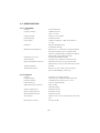
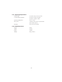
PHONETIC ALPHABET:
To help make call letters more clearly understood, and to assist in spelling out similar
sounding or unfamiliar words, radiotelephone users employ the international phonetic
alphabet.
Phonetic Alphabet:
A
-
ALPHA
B
-
BRAVO
C
-
CHARLIE
D
-
DELTA
E
-
ECHO
F
-
FOX-TROT
G
-
GOLF
H
-
HOTEL
I
-
INDIA
J
-
JULIET
K
-
KILO
L
-
LIMA
M -
MIKE
N
36
-
NOVEMBER
O
-
OSCAR
P
-
PAPA
Q
-
QUEBEC
R
-
ROMEO
S
-
SIERRA
T
-
TANGO
U
-
UNIFORM
V
-
VICTOR
W -
WHISKEY
X
-
X-RAY
Y
-
YANKEE
Z
-
ZULU