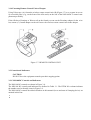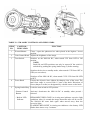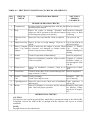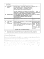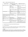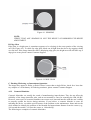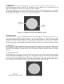
1
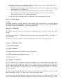
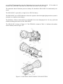
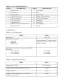
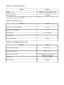
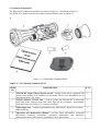
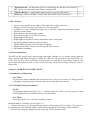
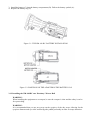
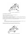
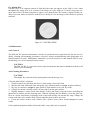
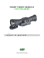
NIGHT VISION MODULE COT NM-108 BC Modern Optical Technologies Safety Summary Before operating this product, carefully read and study this Operation and Maintenance Manual. The COT NM-108 BC night vision module is a precision electro-optical instrument and requires careful handling. To avoid physical danger or equipment damage when using the COT NM-108 BC, follow all WARNINGS, CAUTIONS and NOTES. Below you will find definitions of the alerts that appear throughout this Manual: WARNING — Identifies a clear danger to the person operating the equipment. CAUTION — Identifies risk of damage to the equipment. NOTE — Serves to highlight essential procedures, conditions, statements, or conveys important instructional data to the user. WARNINGS: • When installing the equipment on a weapon, be sure the weapon is clear and the safety is on before proceeding. • It is recommended that you use an eyecup on the eyepiece of the day scope, allowing for the eyepiece diameter and eye relief and having side paddle preferably in order to escape detection. • The light from the infrared illuminator is invisible to the unaided eye. However, the light can be detected by other night vision devices. CAUTIONS: • DO NOT dismantle the equipment. • Keep the equipment clean. Protect it from moisture, dramatic temperature changes, and electric shocks. • • • • • • • DO NOT drop or hit the equipment. Protect the equipment from overexposure to light: DO NOT activate the equipment in daylight with the objective lens cap removed; DO NOT aim the equipment at bright light sources (a fire, car headlights, lanterns, street lamps, room lights, etc.). DO NOT force the equipment controls past their stopping points. DO NOT leave the equipment activated during breaks in operation. Verify that the equipment is off before installing a battery. DO NOT store the equipment with the battery still in it. To avoid deformation or damage, remove the light suppressor from the COT NM-108 BC before placing the equipment in storage. Thoroughly clean and dry each item before placing them into the storage case. NOTES: • Optical axes of the COT NM-108 BC and day scope should align. It is not recommended for the distance between the axes to exceed 3 mm. If the difference in the axis heights of the COT NM108 BC and day scope above the weapon rail exceeds 3 mm, you will need to replace the day scope mounting rings or monoblock. • At operating temperatures below -20 °C, alkaline battery life will be severely reduced. Under said conditions, the use of lithium battery is recommended. • The equipment requires some level of ambient light (moonlight, starlight, etc.) to function correctly. • • Performance of the device in nighttime conditions depends on the level of ambient light in the environment. Please remember the following: — The level of ambient light is reduced by the presence of clouds, shade, or objects that block natural light (trees, buildings, etc.). — The equipment is less effective when operated in shadows and other darkened areas. — The equipment is less effective when operated in rain, fog, sleet, snow, dust or smoke. — The equipment will not “see” through dense smoke. For the purpose of returning defective components, retain all packaging materials. How to Use This Manual USAGE You must familiarize yourself with this entire manual before operating the equipment. Before performing any kind of maintenance on your COT NM-108 BC, read the section on maintenance in its entirety. Follow all WARNINGS, CAUTIONS, and NOTES. MANUAL OVERVIEW The Manual contains sections on operating and maintaining the COT NM-108 BC night vision module. Throughout this Manual, COT NM-108 BC will be referred to as the NM-108 BC , “the device”, or “the equipment”. Reference data for the estimation of ambient illumination levels can be found in Appendix A. Chapter 1. INTRODUCTION 1.1 General Information 1.1.1 Type of Manual Operation and Maintenance (including a List of Spare Parts). 1.1.2 Model Number and Equipment Name COT NM-108 BC 1.1.3 Purpose of Equipment The COT NM-108 BC is a night vision system intended for use in conjunction with a daytime sight, or riflescope (hereafter referred to as a “day scope”). When mounted on a weapon in front of an existing day scope, the NM-108 BC adds to the scope’s capabilities a night vision function (up to range of 900m), without affecting the boresight. Advisable day scope magnification values are 3 to 12X (4 to 10X are optimal). The NM-108 BC is compatible with most commercial and military specification day scopes, and fits any Picatinny MIL STD 1913 or Weaver rail via the quick release mount. An optional long-range IR-illuminator enables use of the NM-108 BC in extremely low light conditions or total darkness. Other additional equipment, such as an infrared laser, red dot sight, etc., may also be installed on the NM-108 BC top Weaver rail. NOTE: The NM-108 BC can also be installed in front of the viewfinders of various instruments to widen the operational illumination range. Chapter 2. DESCRIPTION AND DATA 2.1 System Description The NM-108 BC consists of two primary parts, as shown in Figure 2-1: the night vision device (hereafter referred to as NVD), and the quick release mount system, or mount. The NM-108 BC is delivered already assembled: the mount (B) should be secured to the rail (A) of the NVD (D) with two screws. A B C D Figure 2-1. NM-108 BC NIGHT VISION CLIP ON SYSTEM The optical-electronic system of the NVD includes four main components: the objective and output lenses, an image intensifier tube, and the wired body (C). The objective lens focuses available light (photons) on the photocathode of the image intensifier tube (IIT). The light energy causes electrons to be released from the cathode. After being amplified, the electron flow represents an intensified version of the original image of the scene. The electrons then strike the IIT phosphor screen, which reacts to them by glow that is visible to the human eye. The im age is projected by the output lens from the IIT screen to infinity, and the resulting image is magnified when viewed through the day scope. As such, when the NM-108 BC mounted in front of the day scope, it converts the latter into a night vision sight. The automatic brightness adjustment system maintains consistent image brightness, even in changing light conditions. The manual gain control (optional feature) allows the operator to refine the image contrast by compensating for overly bright or extremely dark conditions. The bright light protection system controls the existing ambient light through a photoreceiver, and cuts off the IIT automatically when the illumination level exceeds the limit of 100…150 lx within 10 seconds. The NM-108 BC turns back on when removed from the excessive light. The automatic shut-off function preserves battery life should the NM-108 BC be inadvertently activated. The NM-108 BC is powered by a single AA or CR123A battery. The NM-108 BC uses a LED indicator to show the operator when the bright light protection system is activated, or to indicate a low battery. The Picatinny / Weaver mount (B) has an adjustable lever-cam clamping device for easy, quick and reliable mounting and removal of the NM-108 BC. The NM-108 BC is shown in Figure 2-2. The ITEM NO. column in Table 2-1 indicates the number used to identify items in Figure 2-2. Figure 2-2. NM-108 BC NIGHT VISION CLIP ON SYSTEM TABLE 2-1. SYSTEM DESCRIPTION ITEM DESCRIPTION ITEM DESCRIPTION 1 Photoreceiver 9 Focus Knob 2 Purge Screw 10 Nut 3 Pivoted Shutter 11 Turn Switch 4 Objective Lens Cap 12 Battery Cap with Adapter 5 Gain Control Knob 13 Control Compartment 6 Top Weaver Rail 14 Main Body 7 Output Lens Cap 15 Cam Lever 8 Double Lever-Lock Quick-Release 16 Lever Holder Picatinny Mount 17 Clamp 2.2 Specifications TABLE 2-2. SYSTEM DATA ITEM Magnification DATA Unity (1X) Boresight Characteristics: — Accuracy — Retention — Repeatability Factory aligned to 0.75 MOA or better Permanent to within 1.5 MOA or better Within 0.75 MOA System Resolution subject to Image Intensifier Tube Resolution: — 45 to 54 lp/mm — 55 to 64 lp/mm — Over 65 lp/mm 0.23 mrad/lp 0.19 mrad/lp 0.16 mrad/lp TABLE 2-3. MECHANICAL DATA ITEM Dimensions (L×W×H) DATA 235×97×80 mm Weight (without Mount and Remote Control) 0.91 kg Weight of Mount 0.1 kg Height of the NM-108 BC Axis above Weapon’s Picatinny / Weaver Rail 40 mm TABLE 2-4. ELECTRICAL DATA ITEM DATA Battery Single AA (1.5V) or CR123A (3V) Cell Life at 20°C 25 hr (1.5V) / 45 hr CR123A (3V) Interrupting Time* 60 minutes * — Optional feature. Interrupting Time setting can be changed at the production stage, or the function can be completely disabled. TABLE 2-5. OPTICAL DATA ITEM Objective Lens Focal Length Objective Lens F/number DATA 108 mm 1:1.5 Focus Range 10 m to infinity Field of View 9o Exit Pupil Diameter 40 mm TABLE 2-6. ENVIRONMENTAL DATA ITEM DATA Operating Temperature -40 to +50 оС Storage Temperature -50 to +50 оС Illumination Required Natural night illumination (overcast starlight to moonlight) 10 m for 30 minutes Immersion MIL-STD-810 Complies 2.3 Standard Components The NM-108 BC standard components are shown in Figure 2-3 and listed in Table 2-7. The ITEM NO. column indicates the number used to identify items in Figure 2-3. Figure 2-3. STANDARD COMPONENTS TABLE 2-7. STANDARD COMPONENTS ITEM NO. DESCRIPTION Q-TY 1 NM-108 BC Night Vision Clip-On System - a night vision device equipped with quick release mount, to be installed on a Picatinny/ Weaver rail. Intended for use in conjunction with a day scope. 1 2 Wireless Remote Control Unit – used to operate the NM-108 BC in short-time activation mode. Ensures quick and silent NM-108 BC activation / deactivation. Delivered with two CR2016 (3V) batteries installed. 1 3 Light Suppressor - a rubber cup installed on the NM-108 BC output lens to reduce light scattering. 1 4 Operation and Maintenance Manual - provides safety information, equipment description, mounting procedures, operating instructions, and preventive maintenance checks and services (including a List of Spare Parts). 1 5 Special Wrench - an instrument used for repositioning the adapter in the NM-108 BC battery cap, depending on the battery being installed. 1 6 CR123А Battery - a single lithium battery used to power the NM-108 BC. 1 7 Soft Case - used for carrying / storage of the NM-108 BC and its accessories. 1 2.4 Key Features • • • • • • • • • • • • Converts your daytime scope, sight, or binoculars into a night vision ones Mounts in front of any day scope with no re-zeroing required Available in a variety of high performing Gen 2+ and Gen 3 image intensifier tube options Wireless remote control Both automatic and manual gain control Powered by a single AA or CR123A battery Bright light cut-off system Bright light cut-off and low battery indications in the viewing area Interrupting time 60 minutes (optional feature) Filled with dry nitrogen to prevent internal fogging Mounts on Picatinny / Weaver rail with a quick release mount Mil Standard compliant 2.5 System Limitations The NM-108 BC requires some ambient light (moonlight, starlight, etc.) to operate. Factors that can reduce natural night light and negatively affect the efficiency and operation of the NM-108 BC include: rain, fog, sleet, snow, and smoke; passing cloud cover and objects that produce shadows; and low-contrast environments such as snow-covered territory, sandy deserts, large bodies of water or grassy hills. Chapter 3. OPERATING INSTRUCTIONS 3.1 Installation and Mounting CAUTION: To protect the image intensifier tube when the device is not in use or when it is being operated in daylight, keep the protective objective lens cap securely fitted over the lens. 3.1.1 NM-108 BC Battery Installation NOTE: At operating temperatures below -20 °C , alkaline battery life will be severely reduced. Under said conditions, the use of lithium battery is recommended. CAUTION: Ensure that the device is off before installing a battery. Install the battery as follows (refer to Figure 3-1): 1. Unscrew the battery cap (E) and check the position of the adapter (D). See Figure 3-2 for the correct positioning of the threaded adapter, which changes depending on the battery being installed. 2. If necessary, change the adapter position in the cap. Use the special wrench. 3. Install the battery (C) into the battery compartment (B). Follow the battery symbol (A). 4. Replace the battery cap (E). Figure 3-1. THE NM-108 BC. BATTERY INSTALLATION Figure 3-2. POSITIONS OF THE ADAPTER IN THE BATTERY CAP 3.1.2 Installing the NM-108 BC on a Picatinny / Weaver Rail WARNING: When installing the equipment on a weapon, be sure the weapon is clear and the safety is on before proceeding. WARNING: It is recommended that you use an eyecup on the eyepiece of the day scope, allowing for the eyepiece diameter and eye relief and having side paddle preferably in order to escape detection. NOTE: Optical axes of the NM-108 BC and day scope should align. It is not recommended for the distance between the axes to exceed 3 mm. If the difference in the axis heights of the NM-108 BC and day scope above the weapon rail exceeds 3 mm, you will need to replace the day scope mounting rings or monoblock. The NM-108 BC on Picatinny rail in front of a day scope is shown in Figure 3-3. Install the NM-108 BC on a Picatinny / Weaver rail in front of a day scope as follows: 1. Remove the output lens cap and place it in the storage case. 2. Remove the light suppressor from the storage case. Put it on the output lens in place of the cap. 3. Unlock the clamping device of the NM-108 BC mount by pushing down on the dogs (A, see Figure 3-4) and unlocking the levers (B). 4. Install the NM-108 BC on the Picatinny / Weaver rail in front of the day scope so that the stops (A, Figure 3-5) slide into the transverse slots on the rail. The light suppressor should cover the day scope’s objective lens. 5. Affix the NM-108 BC to the rail by locking the levers (B, Figure 3-4). 6. Verify that the clamping device is firmly holding the NM-108 BC. If necessary, adjust the clamping device’s lever-cam locks as detailed in Part 3.1.4 (Clamping Device Adjustment). Figure 3-3. THE NM-108 BC INSTALLED ON A PICATINNY RAIL IN FRONT OF A DAY SCOPE Figure 3-4. MOUNT. TOP VIEW Figure 3-5. MOUNT. UNDERSIDE VIEW 3.1.3 Clamping Device Adjustment Adjust the mount clamping device as follows (refer to Figure 3-6): 1. Remove the NM-108 BC from the weapon. 2. With the clamping device unlocked (as shown in Figure 3-6), push the cam (B) towards the arrow, which will cause the nut (A) to slide out of its hollow. 3. To tighten / loosen the clamping device, push down on the cam (B) and turn the nut (A) CW/ CCW respectively, in one-two increments (see note below). Much like when the cam (B) is released, backward-moving springs will cause the nut (A) to slide back into its hollow. NOTE: The eight-sided nuts of the mount lever-cam locks will only fit into their hollows only if turned in one of the discrete positions using increments equal to 360o/8. 4. Verify that the adjusted lever-cam lock is firmly holding the NM-108 BC. 5. Repeat the procedure to adjust the clamping device’s second lever-cam lock. Figure 3-6. CLAMPING DEVICE ADJUSTMENT 3.1.4 Fastening Remote Control Unit to Weapon Using Velcro tape (A), fasten the wireless remote control unit (B) (Figure 3-7) to a weapon in an eas ily accessible place (e.g., on the front of the rifle stock) on the side of the NM-108 BC’s control compartment preferably. If the rifle has a Picatinny or Weaver rail on the forend you can use the Picatinny adapter for the wireless remote (C). Install adapter on the rail. Insert the wireless remote control unit in the adapter. Figure 3-7. REMOTE CONTROL UNIT 3.2 Controls and Indicators CAUTION: DO NOT force the equipment controls past their stopping points. 3.2.1 NM-108 BC Controls and Indicators The NM-108 BC controls are shown in Figure 3-8. The MN-108 BC controls and indicators are defined in Table 3-1. The ITEM NO. column indicates the number used to identify items in Figure 3-8. The NM-108 BC controls described elsewhere in this manual (levers and nuts of clamping device) are omitted in this Part. Figure 3-8. NM-108 BC CONTROLS TABLE 3-1. NM-108 BC CONTROLS AND INDICATORS ITEM NO. CONTROL / INDICATOR FUNCTION 1 Pivoted Shutter Closes / opens the photoreceiver when placed in the highest / lowest position. 2 Gain Control Knob Adjusts the brightness of the image. 3 Turn Switch Switches on the NM-108 BC, when turned CW from OFF to ON position. NOTE: Both ON and STB positions can only be entered if the switch is unlocked by pushing the spring-loaded stop (5) before turning. Switches the device to standby mode, when turned CCW from OFF to STB (see note above). Switches off the NM-108 BC, when turned CCW/ CW from ON/ STB to OFF. 4 Focus Knob Focuses the objective lens. Adjusts for sharpest view of the scene. The total focus range is covered with 1.5 turn of the knob. Directions of focus (sharper to softer) are designated by a double arrow on the knob. 5 Spring-loaded Stop Locks the turn switch in OFF position. - Remote Control Button Activates/ deactivates the NM-108 BC in standby when pressed / released. - Built-in LED Indicator PERMANENT RED GLOW in viewing area indicates excessive light conditions. After 10 seconds the image intensifier tube will be cut off. The NM-108 BC turns back again when moved away from the excessive light. FLASHING RED LIGHT in viewing area indicates a low battery. LED flashes three times every 3 minutes. 3.3 Operating Procedures 3.3.1 Operating NM-108 BC Operating procedures should be performed in night light conditions only. CAUTION: USE OF THE CO-LR IN BRIGHTLY LIT CONDITIONS MAY DAMAGE THE IMAGE INTENSIFIER TUBE. CAUTION: PAY ATTENTION TO THE CAUTION NOTICE ON THE OBJECTIVE LENS CAP: “DO NOT REMOVE IN DAYLIGHT”. 1. Verify that the battery is installed as required. 2. Perform a visual estimation of the illumination level in the viewing area, using the reference data presented in Appendix A. You can begin operating the NM-108 BC if the illumination level is less than 1 lx. 3. Remove the objective lens cap and place it over the lens’ housing. CAUTION: BEFORE REMOVING THE PHOTORECEIVER IS OPEN. OBJECTIVE LENS CAP, VERIFY THAT THE 4. Verify that there are no bright light sources in the NM-108 BC field of view. Turn the device on. After a slight delay, a green glow will appear in the day scope’s output lens. CAUTION: AVOID EXPOSING THE DEVICE TO BRIGHT LIGHT SOURCES SUCH AS FIRELIGHT, HEADLIGHTS, SEARCHLIGHTS, ETC., AS THESE CAN DAMAGE THE NM-108 BC. 5. To operate the NM-108 BC in short-time activation mode, turn the device on standby. To activate the NM-108 BC, press and hold the remote control button. Release the remote control button to deactivate the NM-108 BC. 6. Observe the scene. Adjust the focus by rotating the NM-108 BC focus knob until the image becomes clear and sharp. 7. Adjust the image contrast by rotating the NM-108 BC gain control knob. 8. If the day scope includes a focusing ring (i.e., parallax adjustment knob), adjust the focus for a parallax free image. 9. Turn on the day scope’s reticle illumination and adjust the reticle brightness. CAUTION: DO NOT LEAVE THE NM-108 BC ACTIVATED IF IT IS NOT BEING USED. NOTE: AUTOMATIC INTERRUPTING TIME IS 60 MINUTES. TO RESUME OPERATION, YOU WILL NEED TO RESTART THE NM-108 BC. 3.3.2 Operating in Changing Light Conditions If a mission must be carried out in changing light conditions, you can deactivate the bright light protection system of the NM-108 BC. To shut down the protection system, close the photoreceiver by flipping up the pivoted shutter. CAUTION: AFTER YOUR MISSION IS COMPLETE, OPEN THE PHOTORECEIVER BY FLIPPING THE PIVOTED SHUTTER DOWN. 3.3.3 Shut-Down Shut-down the NM-108 BC as follows: 1. 2. 3. 4. 5. 6. Turn the device OFF. The green glow will disappear. Place the cap over the objective lens. Remove the NM-108 BC from the weapon. Remove the light suppressor from the output lens. Replace the cap on the output lens. Remove the batteries. CAUTION: DO NOT STORE THE EQUIPMENT WITH THE BATTERY STILL IN IT. CAUTION: REMOVE THE LIGHT SUPPRESSOR FROM THE NM-108 BC TO AVOID DEFORMATION OR DAMAGE. 7. Ensure that the NM-108 BC and any accessories are clean and dry before placing them into the storage case. 8. Place the NM-108 BC and any accessories into the storage case. 9. Store the NM-108 BCand accessories in the appropriate locations in the case and close the cover. Chapter 4. PREVENTIVE MAINTENANCE AND TROUBLESHOOTING 4.1 Preventive Maintenance Checks and Services (PMCS) Table 4-1: Preventive Maintenance Checks and Services, has been provided so that you can keep your equipment operable and in good condition. Perform all functional tests in the order listed in Table 4-1. Operating Procedures are detailed in Chapter 3. Always observe any CAUTIONS that appear in the table. Explanation of Table Entries: SEQ NO. column. Sequence numbers are for reference and appear in the order required to perform checks and services. LOCATION / ITEM TO CHECK / SERVICE column. Indicates the location and the item to be checked or serviced. PROCEDURE column. Details the checking / servicing procedure. NOT FULLY MISSION CAPABLE IF… column. Indicates what faults will prevent your equipment from operating successfully. TABLE 4-1. PREVENTIVE MAINTENANCE CHECKS AND SERVICES SEQ. NO. ITEM TO CHECK CHECKING PROCEDURE NOT FULLY MISSION CAPABLE IF: BEFORE OPERATION CHECKS 1 Completeness Inventory items by comparing them with the data Items are missing. specified in this manual. 2 Body Inspect for cracks or damage. Scratches and Cracked or damaged. gouges are OK if operation is not affected. Inspect Purge screw or knob for missing parts (purge screw, knobs). is missing. 3 Objective Lens Cap Inspect for cuts, tears and dirt. Clean as required. 4 Output Lens Cap Inspect for dirt or O-ring damage. Clean as re- Cap is not held up on quired. the lens housing. 5 Battery Compart- Check to make sure the adapter is present. Check Retainer is broken. ment / Cap with for corrosion, cap damaged or retainer breaks. Cap, O-ring or Adapter Check O-ring for cuts or damage. adapter is damaged or missing. 6 Switch Check for operation (without battery). 7 Lenses Inspect for cleanliness, scratches, chips or cracks. Chipped or cracked. Clean as required. Scratches hinder vision through the NM108 BC. 8 Photoreceiver Inspect for cleanliness, scratches. Clean as re- Photoreceiver is damquired. aged. 9 Focus Knob Check to ensure there is free rotation through full range of travel (1.5 turn). 10 Remote Unit 11 Light Suppressor Inspect for cuts or tears. Check ease of installation Light suppressor is and removal. torn or cut. 12 Mount Control Check for damage. Check Velcro tape for wear. Cap is torn or cut. Switch is inoperative. Knob is inoperative. Damaged. Unit tape is missing. or Inspect for damage or corrosion, and for missing Damaged. Some parts parts. Check for proper operation. are missing. Clamping device is inoperative. OPERATIONAL CHECKS CAUTION: The objective lens cap has an optical filter, which allows operational testing of the NM-108 BC in daylight. Activate the NM-108 BC in daylight with the objective lens cap on or in dark conditions. NOTE: Daylight checks are described below. CAUTION: DO NOT forget to open the photoreceiver after finishing operational checks 13 NM-108 BC Switch Insert the battery. Remove the output lens cap. No green glow. Close the photoreceiver by flipping up the pivotal shutter. Turn the switch to ON position. Look for green glow (after a slight delay) in viewing area. Open the photoreceiver by flipping the pivotal Green glow is shutter down. Look through the output lens and present, yellow glow wait about 10 seconds for green glow to disappear. is absent. 14 Remote Control Close the photoreceiver. Put the device in STB. Green glow is absent. Press and hold the remote control button. Look for the green glow in output lens. Release the button. Turn the device off. 15 Focus Knob Turn the device on. Rotate the knob to ensure it Knob does not adjust adjusts for focus. for focus. 16 Gain Control Knob Rotate the gain control knob to ensure it changes Knob does not adjust the screen brightness. the screen brightness. 17 Viewed Image Inspect for any operational defects (refer to Sec- Shading, edge glow, tion 4.3: Inspection Criteria for Proper Image In- flashing, flickering, tensifier Tube Operation). and intermittent operation, or excessive cosmetic defects are found. AFTER CHECKING PROCEDURES 18 Turn off the NM-108 BC. Replace the protective cap on the NM-108 BC output lens. Remove the batteries. Return the NM-108 BC and all accessories to the storage case. 4.2 Operator Troubleshooting The purpose of troubleshooting is to identify the most commonly occurring equipment malfunctions, their probable causes, and the corrective actions required to fix them. Table 4-2 lists the common malfunctions that may occur during the operation or maintenance of the NM-108 BC. Perform the tests, inspections, and corrective actions in the order listed in the table. This table cannot list all of the malfunctions that may occur with the NM-108 BC, or all of the tests and corrective actions that may be necessary. If you experience an equipment malfunction that is not listed, or is not fixed by the corrective actions listed in the table, please contact Armasight’s Customer Service center. TABLE 4-2. OPERATOR TROUBLESSHOOTING MALFUNCTION PROBABLE CAUSE / TEST/ INSPECTION Equipment fails to activate. Battery is missing or improperly installed. Battery is dead. Battery surfaces or contacts are dirty or corroded. Poor image quality. Check focus. Objective and output lenses are dirty. Damaged optical components. CORRECTIVE ACTION Insert battery or install it correctly. Replace battery. Clean the contact surfaces with a pencil eraser and / or alcohol and cotton swabs. Remote control unit is damaged. Please contact Customer Support. Remote control batteries are Replace the batteries as per Part dead. 4.4.3. Defective image intensifier tube. Please contact Customer Support. Refocus. Thoroughly clean the surface of each lens. Please contact Customer Support. LED indicator fails to activate. Visual inspection. Please contact Customer Support. The NM-108 BC affects bore- Factory alignment is broken. sight after installation or during the firing. Please contact Customer Support. Hindered rotation of the bat- Dirty cap thread. tery cap. Damaged cap thread. Clean the thread. Please contact Customer Support. Battery adapter difficult to re- Check for damaged adapter and If damaged please contact Cusmove. battery cap. tomer Support. Light visible around light sup- Incorrect position of the NM-108 pressor. BC relative to the day scope. Check the light suppressor resilience. 4.3 4.3.1 Align the NM-108 BC position relative to the day scope. If light suppressor is defective please contact Customer Support. Inspection Criteria for Proper Image Intensifier Tube Operation Operational Defects Operational defects relate to the reliability of the intensifier, and are an indication of instability. If identified, the user will need to return the NM-108 BC immediately. Operational defects include shading, edge glow, flashing, flickering, and intermittent operation. A. Shading If shading is persistent, you will not be able to see a fully circular image (Figure 4-1). Shading is a very dark, high-contrast area with a distinct line of demarcation present, and you cannot see an image through it. Shading always begins on the edge and will eventually migrate inward until it spans across the entire image area. If you notice shading with your device, please contact Customer Support. Figure 4-1. SHADING NOTE: VERIFY THAT ANY SHADING IS NOT THE RESULT OF IMPROPER EYE-RELIEF ADJUSTMENT. B. Edge Glow Edge glow is a bright area (it sometimes appears to be coloring) in the outer portion of the viewing area (see Figure 4-2). To check for edge glow, block out all light from the device by cupping a hand over the lens. If the image intensifier tube is displaying edge glow, the bright area will still show up; if edge glow occurs please contact Customer Support. Figure 4-2. EDGE GLOW C. Flashing, Flickering, or Intermittent Operation The image may appear to flicker or flash. If there is more than a single flicker, check for a loose battery adapter or a weak battery. If flickering continues, please contact Customer Support. 4.3.2 Cosmetic Blemishes Cosmetic blemishes are usually the result of manufacturing imperfections. They do not affect the reliability of the image intensifier tube, and are not normally a cause for returning the NM-108 BC. However, some types of cosmetic blemishes can worsen over time and interfere with the user’s ability to properly operate the device during missions. If you believe a cosmetic blemish is cause for returning the device, record the specific nature of the problem on the maintenance forms and use the clock method to identify the position of the blemish and approximate distance from the center (e.g., 5:00 toward the outside, 2:30 near the center, or 1:00 midway). The following are examples of cosmetic blemishes: A. Bright Spots A bright spot is a small, non-uniform bright area that may flicker or appear constant (Figure 4-3). Not all bright spots make the NM-108 BC returnable. Cup your hand over the lens to block out all light. If the bright spot remains, please contact Customer Support. Bright spots usually go away when all light is blocked out. Verify that any bright spots are not simply the result of bright light in the area you are observing. Bright spots are acceptable if they do not inter fere with the user’s ability to view the scene or perform missions. Figure 4-3. EMISSION POINTS AND BRIGHT SPOTS B. Emission points Emission points are steady or fluctuating pinpoints of bright light in the image area that do not go away when all external light is blocked from the objective lens (Figure 4-3). The position of an emission point within the image area does not move. Not all emission points are cause to return the NM108 BC. Verify that emission points are not simply light sources present in the scene you are observ ing. Emission points are acceptable if they do not interfere with the user’s ability to perform missions. C. Black Spots Black spots are cosmetic blemishes in the image intensifier or debris between the lenses. Black spots are acceptable as long as they do not interfere with the user’s ability to observe the scene. No action is required if this condition is present, unless the spots interfere with the operator’s ability to perform missions. D. Fixed-pattern Noise Fixed-pattern noise is usually a cosmetic blemish characterized by a faint hexagonal (honeycomb) pattern that appears throughout the viewing area. This typically occurs in excessively lit environments or when viewing very bright lights (See Figure 4-4). This pattern can be seen in every image intensifier if the level of light is high enough. This condition is acceptable as long as the pattern does not in terfere with the user’s ability to view an image or their ability to perform missions. Figure 4-4. FIXED PATTERN NOISE E. Chicken Wire Chicken Wire is an irregular pattern of dark thin lines that can appear in the field of view, either throughout the image area or in sections of the image area (See Figure 4-5). In the worst-case sce nario, these lines will form hexagonal or square, wave-shaped lines. No action is required if this condition is present, unless it interferes with the user’s ability to view an image or their ability to perform missions. Figure 4-5. CHICKEN WIRE 4.4 Maintenance 4.4.1 General The NM-108 BC operator maintenance consists of operational tests, inspections for the unit serviceability, cleaning and mounting procedures, corrective actions (troubleshooting and replacement of a limited number of parts). Maintenance instructions covered elsewhere in this manual (PMCS, troubleshooting, etc.) are not repeated in this section. CAUTION: The NM-108 BC is a precision electro-optical instrument and must be handled carefully at all times to prevent damage. 4.4.2 Cleaning Procedures CAUTION: Thoroughly dry each item before placing them into the storage case. Clean the NM-108 BC as follows: 1. Gently brush off any dirt from the device’s body using a clean soft cloth. 2. Moisten the cloth with fresh water and gently wipe external surfaces (except for glass surfaces). 3. Dry any wet surfaces (except for glass surfaces) with another clean, soft, dry cloth. 4. Using a lens brush, carefully remove all loose dirt from the glass surface. 5. Slightly dampen a cotton swab with ethanol. Gently and slowly wipe the lenses (including the photoreceiver and the pivotal focusing lens). Without touching the lens holders, clean the glass surfaces in circular movements, beginning in the centre and moving out towards the edge. Change the cotton swab after each circular stroke. Repeat until the glass surfaces are clean. 6. Clean the battery surfaces and contacts with a pencil eraser and/or alcohol-dampened cotton swabs. Clean optional equipment with a soft brush (cloth), soap, and water as required. 4.4.3 Battery Removal and Replacement Refer to Parts 3.1.1 for the NM-108 BC battery installation procedure, respectively. Replace the remote control batteries as follows: 1. Using a screwdriver, unscrew the four screws (A, Figure 4-6) that affix the cover to the bottom of the unit. Remove the cover. 2. Replace the batteries with two new ones (CR2016, 3V). Stack the batteries in its place under the leaf contact spring with the minus contacts directed towards the electric board, as the minus sign etched on the board indicates. 3. Replace the cover and retighten the screws (A). Figure 4-6. REMOTE CONTROL UNIT. BATTERY INSTALLATION APPENDIX А (Reference) ESTIMATION OF AMBIENT ILLUMINATION LEVEL Table A-1 lists some common natural light conditions and their corresponding representative illumination values. TABLE А-1. STANDARD VALUES NATURAL LIGHT Standard Natural Light Conditions CONDITIONS AND ILLUMINATION Illumination Value, lx Quarter moon 0.05 Full moon 0.30 Late twilight sky 1.00 Twilight sky Overcast sky in the daytime 10.00 500.00