1
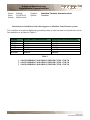
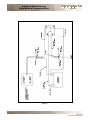
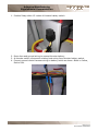
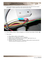
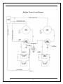
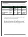
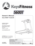
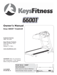
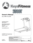
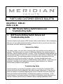
PARTS AND CUSTOMER SERVICE BULLETIN
BULLETIN #: 2006-01
DATE: 1/6/06
1.
1.
BEP Thruster Battery Switch Failures and
Troubleshooting Guide
BEP Thruster Battery Switch Failures and
Troubleshooting Guide
We have received some reports of BEP thruster battery switch failures. After investigating
this issue we have determined these battery switches can fail to connect over time when
the thruster controller switches are pressed.
Nature of the Failure
The battery switch, over time, fails to connect when the controllers on the switches are
pressed. The battery switch is sensitive to differences between the reference ground, a
black wire, and the switched ground, a red wire. When the switching voltage between the
two grounds exceeds 0.8 volts of DC current the battery switch will try to disconnect while
in the auto mode. Two contributing factors can be loose wire connections and a long
length of the circuit from the switch to the relay. We have included step-by-step
instructions to assist in the correction of failed thruster battery switches. In the event you
encounter a Meridian Yacht needing this correction, please telephone our Customer
Service team to obtain an authorization.
Troubleshooting Guide
Imtra Corporation has reported a significant number of Docking On Command (DOC)
controls returned to them as defective that, when checked, tested good. In an effort to
assist our dealers in accurately diagnosing the source of failures in the DOC system we
have also included with this bulletin a troubleshooting guide for our thrusters. In the
event the source of a thruster problem is not able to be identified, please telephone or email our Customer Service team for assistance before ordering replacement parts.
P.O. Box 9029
Everett, WA 98206
U.S.A.
Phone: (877)-861-6494
Fax: (866)-937-8207
Arlington Manufacturing
Supplemental Documentation
Model:
Date:
Author:
Multiple
11/06/2005
Mark Housel
Subject:
Option:
Meridian Thruster Ground control
Standard
Instructions for installation of the following parts on Meridian Yacht Thruster systems.
The intention is to add an additional grounding relay to each thruster to shorten the circuit.
Part selection is as listed in Table 1.
MODEL
341NSB
368MY
391SB
408MY
411SB
459CMY
BOW THRUSTER HARNESS
1816254
1816255
1816254
1816154
1816254
1816254
STERN THRUSTER HARNESS
1816255
1816254
1816256
1816254
1816255
1816254
Table 1
1. 1816254 MERIDIAN 06,HARNESS,THRSTR CNTRL GND 1M
2. 1816255 MERIDIAN 06,HARNESS,THRSTR CNTRL GND 2M
3. 1816256 MERIDIAN 06,HARNESS,THRSTR CNTRL GND 3M
Page 1 of 4
Last Printed 12/22/2005
Arlington Manufacturing
Supplemental Documentation
Figure 1
Page 2 of 4
Last Printed 12/22/2005
Arlington Manufacturing
Supplemental Documentation
1. Position Relay within 12 inches of thruster battery switch.
2. Route fuse and ground wiring to nearest thruster battery.
3. At thruster switch, disconnect existing boat wiring from thruster battery switch.
4. Connect ground control harness wiring to battery switch as shown: Black to Yellow,
Red to Red.
Page 3 of 4
Last Printed 12/22/2005
Arlington Manufacturing
Supplemental Documentation
5. Connect Boat harness to ground control harness Boat side Red to Ground control
yellow/Black. Isolate and tie back other boat harness wiring.
6. Connect Battery wiring, Yellow to Negative (-), Red with Fuse-holder to Positive (+
+)
7. Test system
a.
b.
c.
d.
e.
Place battery switch in Auto position
Press both “on” switches on D.O.C. Controller
Battery switch should close and red indicator lights should turn on.
Operate thruster in both directions.
Depress “off” button on D.O.C. Controller, battery switch should open and
thruster should be inoperative at this time.
Page 4 of 4
Last Printed 12/22/2005
Meridian Thruster Battery Distribution System.
Basic Operation of the thruster battery switches is accomplished by remote. By depressing
both “on” switches at the controller the switches are closed connecting the batteries to the
thrusters.
The Controller is powered from a fuse connected to the line side of the Bow thruster battery
switch. When energized it provides a 12V signal used to trigger a relay. Refer to Figure 1.
The relay is typically located behind or near the battery management or DC main panel,
depending on the model of boat. When triggered this relay connects the DC ground buss to
the red wire at the thruster battery switch. The thruster battery switch compares this to the
reference ground attached to the black wire at the battery switch. If they agree within 0.8VDC
the battery switch closes. Connecting the battery to the thruster. At this time thruster control is
available from the helm.
Failure Modes
When the battery switch operates in “Manual”, but no longer operates in “Auto”:
The battery switch is sensitive to differences between, reference ground (black wire) and
switched ground (red wire). When the switching voltage between these two wires is greater
than 0.8Vdc, (figure 2) the battery switch will try to disconnect, while in auto mode. This can
happen over time, if connections are loose and the circuit length from the switch to the relay is
long.
If this condition exists for a period of time, the battery switch will also fail due to being only
partially connected, while carrying the full load of the thruster. If this occurs the battery switch
will no longer operate in the manual mode. It is recommended that the battery switch be
replaced if the thruster system has operated under this condition.
T HRUST ER BAT T ERY SWIT CH T S&R
1 OF 6
GUIDE.DOC
ORIG INAT OR: MARK HO USEL
12/22/2005
Meridian Thruster Control Diagram
Figure 1
2
Basic Thruster battery switch control
Figure 2
3
Trouble Shooting Guide
1. Perform resistance checks to validate wiring and components up-circuit of battery switch.
This will confirm that controller wiring and cabin relay are operating correctly.
Check
Verify Thruster controller and
original cabin ground relay work
as designed
Verify Thruster controller and
original cabin ground relay work
as designed
Verify Thruster controller and
original cabin ground relay work
as designed
System
Condition
Thruster
Controller off.
E-Battery switch
in auto.
Thruster
Controller off
E-Battery switch
in auto.
E-Batt switch
Black wire,
resistance to
ground
E-Batt switch
Red wire,
resistance to
ground
Thruster
Controller on
E-Battery switch
in auto.
E-Batt switch
Red wire,
resistance to
ground
Check
Expected
value
Indicates
Low resistance
typically less
than 2 Ω
Good switch ground
High resistance
typically greater
than 1M Ω
Controller off, battery
switch off.
Low resistance
typically less
than 2 Ω
Battery switch should
close, thruster should
be operational,
Controller and cabin
wiring good.
Table 1
2. Verify Thruster Motor is operational: Note if problem has progressed to complete battery
switch failure, this check will fail and be reevaluated later. Place the battery switch in the
manual position. Turn on thruster controller, operate thruster.
3. If Battery Switch does not operate in auto-mode: Battery switch in Auto mode, turn
Thruster controller on. Using two Jumper wires at Electric Battery switch connect red wire to
black wire and connect to thruster battery ground. Battery switch should close. If switch
closes under this condition, the latching voltage is from ground to switch ground is too high.
Add thruster grounding harness as shown in figure 3. Select your part number for the table
listed on the next page (table 1)
4
MODEL
341NSB
368MY
391SB
408MY
411SB
459CMY
BOW THRUSTER
1816254
1816255
1816254
1816154
1816254
1816254
STERN THRUSTER
1816255
1816254
1816256
1816254
1816255
1816254
Table 2
1. 1816254 MERIDIAN 06,HARNESS,THRSTR CNTRL GND 1M
2. 1816255 MERIDIAN 06,HARNESS,THRSTR CNTRL GND 2M
3. 1816256 MERIDIAN 06,HARNESS,THRSTR CNTRL GND 3M
Diagram with ground control harness and relay installed (typical bow and stern)
Figure 3
5
1. Mount relay within 12 inches of battery switch
2. Connect fused wire to positive battery post and battery ground to Negative battery post of
Thruster battery.
3. At thruster battery switch connect Yellow wire to Black wire on switch, Connect Red/grey
wire to red wire on Thruster battery switch.
4. Connect Yellow/Black wire to Vessel harness red wire. Tie back
6