1
Model R184
16 x 1 Matrix Switch
User’s Manual
PC Software 80203-1.12b
Monroe Electronics
100 Housel Ave
Lyndonville NY 14098-0535
800-821-6001 ⏐585-765-2254 ⏐ fax 585-765-9330
www.monroe-electronics.com
111007
DESCRIPTION
The Monroe Electronics Model R184 is a 16 X 1 RF matrix switch that operates from 5 to
1000 MHz.
Control is by RS485 serial input, from a local PC that has an RS485 serial port, or via
a USB to RS485 adaptor that is available for PCs not having a local RS485 port.
A LAN to RS485 adaptor connected to the unit that commuinicates with the PC over an
Ethernet LAN is also provided for in the software supplied with the unit.
[Monroe can supply both of these adaptors. See data sheets at the end of the manual.]
The units may be operated as a single, 16 X 1 switch, or interconnected in one location as a
matrix with up to 17 units switching 256 inputs to a single output
You may also control up to 128 individual units on one RS485 serial data connection, with
control of one of 16 inputs to one output on each of the R184 units.
SPECIFICATIONS
FREQUENCY RANGE
5 – 1000 Mhz
FREQUENCY RESPONSE
<+/- 1.5 dB 5-1000 MHz
RF LEVEL
-3 to +50 dBmV
INPUT IMPEDANCE
75 ohms
ISOLATION
>30 dB 5-1000 MHz
INSERTION LOSS
<1 dB 5-1000 MHz
RETURN LOSS
>15 dB 5-1000 MHz
MER DEGRADATION
<3 dB 5-1000 MHz
2
INSTALLATION
Hardware
Single Unit
• Record Unit ID shown on rear panel of R184 being installed.
• Mount unit in rack, and connect the output port of the R184 via coaxial cable to the desired
device.
• Connect the RF sources to be switched to the RF inputs numbered 1 to 16.
• Record which RF input connects to which RF source.
• Plug in the 3 pin plug for the RS485 cable to the rear panel jack, then attach the power
supply plug to the rear panel.
• Plug the power supply into a power outlet.
• The software instructions later describe setting up the units.
Multiple Single Units
• Record the Unit IDs for all units being installed.
• Note which unit will be connected with the last plug on the RS485 cable.
• Mount units in racks as desired.
• As with the single unit, make the output connections as desired, connect the RF inputs and
note which input goes to which switch on which unit.
• Connect the RS485 plugs to the units, and connect and plug in the power supplies. Ensure
that the end connector on the cable goes to the unit where the RS485 termination will be
turned on.
• The software instructions later describe setting up the units.
3
Matrix Setup
• To use the R184 units as a matrix, one unit is designated as a master unit, and the other
units as slave units.
• Record the ID’s of the units, noting which unit will be the master unit.
• Mount the units where desired, realizing that the outputs of each of the slave units MUST be
routed to one of the sixteen inputs on the master unit. The master unit output is then
connected to the device receiving the RF input selected.
• After mounting, connect the RS485 cable plugs to the master and slave units. Remember to
connect the end plug on the cable to the unit designated the master unit.
• Plug in the power supplies to the rear panels of the units, and then to power outlets.
• Refer to the software instructions to set up the software for the matrix units.
4
Software Installation
• Insert the CD containing the software setup into your PC CD drive.
When the following screen displays, click on Installation to begin.
• If the above screen does not appear, click Start, then Run, then browse to the CD drive
containing the disc, and left click on the program logo being displayed, and follow the
instructions as before.
5
• Click on Next to continue the installation.
• Click on Yes to agree with the software agreement.
• Input your Name and Company in the User Information panel, then left click Next.
• If the location for installation is correct for your computer, click on Next. If not,
set up your own location or browse to one that works for you.
7
• This selection is used for icons. Unless you have some other selection, click Next.
• This screen describes the software installation settings. Click Next to continue.
8
• Check if you want to read the ReadMe file, and if you want to launch the program now.
• Click on Finish to complete the installation.
9
• After the software is installed, write down the unit IDs of the individual units for the
configuration to follow.
• It is advantageous to name the individual units and record the name with the unit ID
numbers.
• If the RF inputs are identified by name, the association of each RF input with its
corresponding port number on an individual switch unit should be recorded. {See page 14
for an illustration.]
• To begin setting up the software with the hardware, click on the R184 on your desktop icon to
open the program.
• Selecting Configure New Unit/Matrix allows us to Select Connection.
• We will illustrate setting up a LAN connection.
• The Comport connection is set up in similarly.
10
• This screen permits input of the IP Address for the Ethernet adaptor being used, and the
Port number it communicates through. These are noted on the R184/98 LAN to RS485
adaptor, and configured for your system by your IT personnel to allow the proper
operation. The example below is set up for a system at Monroe Electronics.
• After entering the information, click OK.
11
Single and Multiple Single Unit Setup
• After selecting Single Unit in the Select Configuration Screen, Enter Unit Name in the space
provided.
• The Unit ID is noted on the rear panel of the R184. Or, if the units are connected and
powered up, select Request Unit ID, and the software will fill it in for you as shown in the
next illustration.
12
• Entering Yes and then Yes in these two screens completes the Single Unit Configuration.
• Select OK to go to the next step.
13
• Entering optional descriptive Port Names for the RF inputs on this unit makes it easier to
remember what is being sent from the output port of the unit. [These names are ONLY stored
on the PC doing the setup.]
• When done, click OK to return to the main menu.
14
• Left click on Operation to open the next screen.
• If this is a single unit, the RS485 Termination should be selected for ON. Notice that there is
only one Unit shown. If multiple units are installed, each one is listed on it’s own line.
• Selecting a Unit , permits editing the configuration, deleting the configuration, turning the
RS485 termination On or Off, or Operates the unit.
• When the units are installed with the RS485 lines to multiple units, the unit connected to the
end plug in the cabling MUST have it’s termination ON, and all other units MUST have their
terminations OFF.
• Select the unit to control, and left click Operate.
15
• Control of the operation of a selected unit is performed from this screen.
• Manually select which input is sent to the output by highlighting the Port and clicking the On
button. Or, double click on the Port.
• If it is useful to scan some switches automatically, we can select which switches to send to
the output - in order - and how often they are switched. Selecting which switches to autoscan is done by entering the last switch to be scanned in the box labeled “Scan limits to port:
(2-16). Scanning begins with switch 1 and ends at the switch number entered in the box.
Click on set timer to enter minutes and or seconds between scanning.
• Start and Stop the Scan at any time by clicking on either Start or Stop as desired.
• Since the unit has a manual switch on the front panel for input selection, the Auto Update
should be selected for on. This ensures that the software operater knows which switch is
actually selected on the unit.
• Clicking the Refresh Screen button also updates the switch state on the unit.
16
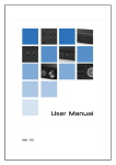
• This is a picture of a single unit connected to a spectrum analyzer. Note that the orange LED
indicates that the termination is set, since it is at the end of the RS485 connection. And that
input 16 is being sent to the spectrum analyzer.
The display is of analog television channel 2.
17
Matrix Setup
• To use the switch units in a matrix configuration, click on Matrix in the Select Configuration,
then enter the required information in the Matrix Configuration screen. The inputs entered
are Master Unit ID , Matrix Name and Number of slave Units.
• When done, select OK.
18
• Enter the Slave Unit id number, and enter a reference name for it. Once this is done,
select OK, then click on Yes on the following screen to configure the matrix. This example
shows the setting of a Matrix with one slave unit.
• Verify that the blue power LED on the master unit is now flashing. This indicates
that this unit has been properly set to be the maseter unit in the matrix.
19
• Input descriptive names for each of the 16 switches on all the Slave Units that have been
entered, one slave unit at a time.
• When completed, select OK. Again, the names are saved ONLY on the PC setting up the
units.
• You will be returned to the main screen.
• Select Operate to begin using the matrix.
20
• Notice that two configurations are shown.
• The first one is to use unit 154 as a single unit, and the second one is to use unit 154 as the
master in a matrix.
• Highlight the matrix selection, then click RS485 Termin. On. [Of course, you have connected
the end connector on the RS485 serial wiring to the Master unit prior to this.]
• Verify that the yellow CNTL Terminal LED on the front panel of the master unit is lit.
• Click on Operate to go to the operation screen.
21
• This is the Matrix Operation screen. The number of the slave unit is indicated. Clicking on
any of the switch numbers in the Slave list will route the input from that switch to the output of
the master. Note that the setup for this matrix has the output of the Slave unit going to the 1
input of the Master. This screen would also display the names associated with each switch,
IF the unit controlling the devices is the setupt PC.
• Switches on any of the units may be used to manually select which input goes to which
output. Note that on a matrix such as this, the combination of an input from one of the slaves
along with the choice of which slave unit goes to the master output requires two selections.
• To be certain that no manual changes have been made, click on Refresh Screen to view the
status of all switches.
• Scanning while in Matrix Operation mode switches each input of each slave unit in series to
the single output. If you wish to scan only the slave units, set the Scan Limits setting the only
those ports on the master unit that are being used as slave inputs.
22
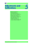
• This is a picture of two units configured as a matrix connected to a spectrum analyzer.
Note that the orange led indicates that the termination is seton the top unit, which is
configured as the master, since it is at the end of the RS485 connection. And that input 16
on the slave unit is active, and is sent into the master unit on input 1. It is being sent to the
spectrum analyzer from the output of the master unit.
The display is of analog television channel 2.
23
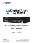
USB to RS485
model
R184/97
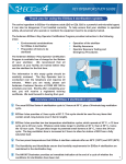
Features
Includes USB-RS485 Converter
• Wiring and Connectors Included
• Installation CD and Software included
for all supported devices.
• Supported devices include R184 switch.
R165 switch and R174 switch
•
Specifications
Input: USB 1.0 or better
Output: RS485, simplex
Unit Power Requirement
Description
This device allows the local control of a model R184 16X1
RF switch, both as a single unit and in a multiple matrix
configuration, from any Windows based computer. The
device connects to an available USB port. Through the
included software, the operator can control in real time - with
options for scanning input ports - all aspects of the R184.
Control of one or more R165 or R174 A/V switch panels is
accomplished with this device.
Power supplied by USB connection
800-821-6001
585-765-2254 | fax 585-765-9330
100 Housel Ave. | Lyndonville | NY | 14098
www.monroe-electronics.com
R184_DS_97_111007.p65
Specifications subject to change without notice.| Printed in USA | Copyright© 2003 |Monroe Electronics Inc.
LAN to RS485
model
R184/98
Features
Includes LAN-RS485 Converter
• Wiring and Connectors Included
• Installation CD and Software included
for all supported products.
• Supported products include R184
16X1 RF switch, R165 and R174
A/V switch panels
•
Specifications
Input: ETHERNET 10/100
BASE T
Output: RS485, simplex
Unit Power Requirement
Power Module Included.
Requires 110 VAC 60 Hz
Description
This device allows the local control of a model R184 16X1
RF switch, both as a single unit and in a multiple matrix
configuration, from any Windows based computer via a LAN.
Using the included software, the operator can control in real
time - with options for scanning input ports - all aspects of the
R184.
Control of one or more R165 or R174 A/V switch panels is
also accomplished with this device.
800-821-6001
585-765-2254 | fax 585-765-9330
100 Housel Ave. | Lyndonville | NY | 14098
www.monroe-electronics.com
R184_DS_97_111007.p65
Specifications subject to change without notice.| Printed in USA | Copyright© 2003 |Monroe Electronics Inc.