1
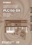
Piano Plug-in Board
Piano Plug-in Board
Carte Plug-in piano
Owner’s Manual
Bedienungsanleitung
Mode d’emploi
Precautions
● Do not expose the plug-in board to direct sunlight,
excessive humidity, high temperatures, excessive dust
or strong vibrations.
● Before handling the plug-in board, be sure to touch a
metal surface to discharge any static electricity which
may be in your body.
● When holding the plug-in board, do not touch the inside
area of the circuit board or apply excessive pressure to
the board, and be sure to protect the board from contact
with water or other liquids.
● Before installing the plug-in board onto a tone generator/sound card, unplug the power connector of your
computer.
● Before connecting the computer to other devices, turn
off the power switches of all devices.
● Yamaha is not responsible for loss of data through computer malfunctions or operator actions.
● The plug-in board contains no user-serviceable parts, so
never touch the inside area of the circuit board or
tamper with the electronic circuitry in any way. Doing
so may result in electrical shock or damage to the plugin board.
YAMAHA CANNOT BE HELD RESPONSIBLE
FOR DAMAGE CAUSED BY IMPROPER
CARE AND USE OF THE PLUG-IN BOARD.
* The company names and product names in this Owner’s Manual are the trademarks or registered
trademarks of their respective companies.
* The screens as illustrated in this owner’s manual are for instructional purposes only, and may
appear somewhat different from the ones of your instrument.
FCC INFORMATION (U.S.A.)
1. IMPORTANT NOTICE: DO NOT MODIFY THIS UNIT!
This product, when installed as indicated in the instructions contained in this manual, meets FCC requirements. Modifications
not expressly approved by Yamaha may void your authority, granted by the FCC, to use the product.
2. IMPORTANT: When connecting this product to accessories and/or another product use only high quality shielded cables.
Cable/s supplied with this product MUST be used. Follow all installation instructions. Failure to follow instructions could void
your FCC authorization to use this product in the USA.
3. NOTE: This product has been tested and found to comply with the requirements listed in FCC Regulations, Part 15 for Class
”B” digital devices. Compliance with these requirements provides a reasonable level of assurance that your use of this product
in a residential environment will not result in harmful interference with other electronic devices. This equipment generates/uses
radio frequencies and, if not installed and used according to the instructions found in the users manual, may cause interference
harmful to the operation of other electronic devices. Compliance with FCC regulations does not guarantee that interference will
not occur in all installations. If this product is found to be the source of interference, which can be determined by turning the unit
”OFF” and ”ON”, please try to eliminate the problem by using one of the following measures:
Relocate either this product or the device that is being affected by the interference.
Utilize power outlets that are on different branch (circuit breaker or fuse) circuits or install AC line filter/s.
In the case of radio or TV interference, relocate/reorient the antenna. If the antenna lead-in is 300 ohm ribbon lead, change the
lead-in to co-axial type cable.
If these corrective measures do not produce satisfactory results, please contact the local retailer authorized to distribute this
type of product. If you can not locate the appropriate, please contact Yamaha Corporation of America, Electronic Service Division, 6600 Orangethorpe Ave, Buena Park, CA 90620
* This applies only to products distributed by YAMAHA CORPORATION OF AMERICA.
CANADA
This Class B digital apparatus complies with Canadian ICES-003.
Cet appareil numérique de la classe B est conforme à la norme NMB-003 du Canada.
• This applies only to products distributed by Yamaha Canada Music Ltd.
• Ceci ne s’applique qu’aux produits distribués par Yamaha Canada Musique Ltée.
2
Congratulations and thank you for purchasing the Yamaha PLG150-PF Piano Plug-in Board!
The PLG150-PF is a custom tone generator designed for use with a variety of Yamaha electronic musical instruments. Foremost, the PLG150-PF can be installed to and integrated with
instruments of the Modular Synthesis Plug-in System (such as the CS6x, CS6R, S80, etc.) It
can also be used seamlessly with the MU128 Tone Generator (as well as other MU-series
instruments and the SW1000XG PCI Audio/MIDI Board). The PLG150-PF provides a wide variety of exceptionally high-quality, authentic keyboard instrument sounds — including piano, electric piano, harpsichord, clav, and others. It features its own built-in EQ, Reverb, Chorus, and
Insertion effects, allowing you to process the sound without having to use the effects resources
of the “mother” device.
The settings and parameters of the PLG150-PF can also be conveniently edited with a Windows PC computer by using the PF Easy Editor software module (included in the XGworks
Music Sequencer software).
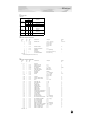
Table of Contents
Overview of the PLG150-PF ..................................... 4
Parameter Structure ............................................... 6
Editing the PF Native Part Parameters
(Modular Synthesis Plug-in System) ................ 13
Specifications ............................................................. 7
Selecting/Editing the PF System Parameters
(Modular Synthesis Plug-in System) ................ 14
About the Included Floppy Disks.............................. 8
Selecting PF Voices (XG Plug-in System) ............. 15
Installing the PLG150-PF ........................................... 9
Enabling and Selecting PF Voices ..................... 15
Included Items ............................................................. 9
Editing the PF Native Part Parameters
(XG Plug-in System) ..............................................17
Required and Recommended Items ...................... 10
Synthesizer/Tone Generator/
Sound Card Compatible with the Modular
Synthesis or XG Plug-in Systems.................. 10
XGworks or XGworks lite
Music Sequencing Software .......................... 10
PF Easy Editor ................................................... 10
Installing and Starting the Plug-in
Editor Software (Windows 95/98) ................... 11
Installing the Software ........................................ 11
Starting the PF Easy Editor ................................ 11
Selecting PF Voices
(Modular Synthesis Plug-in System) ................ 12
Enabling and Selecting PF Voices ..................... 12
Selecting/Editing the PF System Parameters
(XG Plug-in System) ..............................................18
Parameters ...............................................................19
PF Native Part Parameters................................. 19
PF System Parameters ......................................23
Appendix .....................................................................24
Voice List ................................................................24
PLG150-PF Voice Effect Parameter List ........... 30
Effect Data Assign Table .....................................33
Parameter List (XG / Modular
Sysnthesis Plug-in System) ............................ 34
MIDI Data Format ..................................................35
MIDI Implementation Chart ................................. 42
3
Overview of the PLG150-PF
The PLG150-PF is a sophisticated tone generator board that provides realistic piano and other keyboard sounds. Utilizing Yamaha’s state-of-the-art AWM2 tone generation system along with true
stereo sampling, the PLG150-PF features exceptionally rich, natural and authentic instrument
voices, to augment the sound palette on the “mother” device.
■ Easy Installation
Once it is connected, the PLG150-PF automatically becomes another sound source in the tone generator/sound card, and can be used as one of the instrument Parts. You can create your own original PF
voices and combine PF voices with the other voices in the “mother” device.
■ 136 Voices and 64-note Polyphony
The PLG150-PF is packed with a total of 132 rich and authentic keyboard voices. Many of the acoustic grand piano sounds have been recorded in stereo for enhanced realism and luxurious tone. The
PLG150-PF also has a huge variety of realistic electric piano voices, covering a broad stylistic range
— from the classic keyboards of the ‘60s and ‘70s, to the crisp and bright digital sounds of recent
years. In addition to the electric grand, harpsichord and clav voices, a variety of combination voices
are also included, letting you play sustained pad and choir sounds, layered with piano. A maximum
64-note polyphony lets you play complex sustained chords and passages, without worrying about
notes being cut off. (For certain stereo and combination voices, the polyphony may be 32 notes or
less.)
■ Built-in Effects
The PLG150-PF also has its own dedicated effects processing. This means that you can apply EQ,
Reverb, Chorus, and even a Insertion effect to the voice, letting you use all of the effects on the
“mother” device for the other Parts.ong.
4
Overview of the PLG150-PF
About the Modular Synthesis Plug-in System
The Yamaha Modular Synthesis Plug-in System offers powerful expansion and upgrade capabilities for Modular Synthesis-Plug-in-compatible synthesizers, tone generators and sound
cards. This enables you to easily and effectively take advantage of the latest and most sophisticated synthesizer and effects technology, allowing you to keep pace with the rapid and multifaceted advances in modern music production.
About the XG Plug-in System
The Yamaha XG Plug-in System offers powerful expansion and upgrade capabilities for XGPlug-in-compatible tone generators and sound cards. This enables you to easily and effectively
take advantage of the latest and most sophisticated synthesizer and effects technology, allowing
you to keep pace with the rapid and multi-faceted advances in modern music production.
5
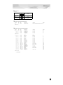
Parameter Structure
Plug-in Board
Plug-in Platform
System Parameter
XG Effect Parameter
XG System Parameter
Reverb
PF Native System Parameter
Chorus
Variation
Part Parameter
Insertion1
XG Part Parameter
Part Parameter
Part Parameter
PF Native
PartParameter
Parameter
XG Part
Insertion2
XG Part Parameter
Part Parameter
PF Native Part Parameter
PF Native
PartParameter
Parameter
XG Part
PF Native Part Parameter
Offset
PF Voice Parameter
Element4
Element3
Element2
Element1
Voice
Reverb
Voice
Chorus
Voice
Insertion
Voice
EQ
The Plug-in voices are made here.
6
Specifications
TONE GENERATOR/MODULES :
AWM2
POLYPHONY :
64 notes maximum (latest note priority; polyphony is expandable *1)
*1 On the CS6x, for example, two boards can be installed for a
maximum of 128 notes; on the MU128, three boards can be
installed for a maximum of 192 notes.
NUMBER OF VOICES :
136 XG voices (PF-XG/A, PF-XG/B)
128 Preset voices
INTERFACE :
Plug-in connector
EFFECTOR :
Reverb, Chorus, Insertion, 2-Band EQ
DIMENSIONS (W x H x D) :
138.5 x 89.0 x 8.5mm
WEIGHT :
72g
INCLUDED ITEMS :
Owner’s Manual, Floppy disk
* Specifications subject to change without notice.
7
About the Included Floppy Disk
The included floppy disk contain editing software for the PLG150-PF as well as demonstration songs
and Voice data for the “mother” device.
To use the editing software and transfer the song/Voice data to your particular “mother” device, you
should have a computer (running Windows 95/98) with a MIDI interface, with the MIDI OUT on the
interface connected to the MIDI IN of the “mother” device. You should also have XGworks (v3.0 or
higher) or XGworks lite installed to your computer; this is necessary to use the editing software
(page 10). For playing back the demonstration songs and transferring the Voice data, you can use
any compatible sequence software (such as XGworks/XGworks lite) or hardware sequencer capable of sending bulk data. Insert the disk into the computer and start the installation.
The following software is included on the disk:
■ PF Easy Editor (page 10)
■ Demonstration Songs
(1) “Fantaisie-impromptu op.66” (02Fanta.mid)
By:
For:
Frederic Chopin
Modular Synthesis Plug-in System devices (CS6x, etc.) and XG Plug-in System devices (MU128, etc.)
(2) “THE PF THEATRE” (02Theatr.mid)
By:
For:
Katsunori Ujiie (Idecs, Inc.)
XG Plug-in System devices (MU128, etc.)
(3) “SOLO-demo” (02Solo.mid)
By:
For:
Katsunori Ujiie (Idecs, Inc.)
Modular Synthesis Plug-in System devices (CS6x, etc.) and XG Plug-in System devices (MU128, etc.)
■ Plug-in Voice Data for CS6x/CS6R/S80
(Modular Synthesis Plug-in System)
This is Plug-in voice data, featuring a total of 64 voices that were created using the PLG150-PF Preset
voices. When the PLG150-PF is installed to PLG1, select the file “01PlgVc1.mid”; when the board is
installed to PLG2, select the file “01PlgVc2.mid.”
For a complete list of these voices, refer to the Plug-in Voice List (page 29).
8
Installing the PLG150-PF
For detailed instructions on installing the PLG150-PF, refer to the owner’s manual of the Plug-incompatible “mother” device (e.g., CS6x, MU128, etc.).
Included Items
The following items have been included in the package of your new PLG150-PF. Please make sure
that you have them all before starting to setup and use the instrument. If an item is missing, contact
the store or dealer from which you purchased the PLG150-PF.
• PLG150-PF board
• PLG150-PF Owner’s Manual (this book)
• Floppy disk
9
Required and Recommended Items
In addition to the included items listed above, you should also have the following:
Synthesizer/Tone Generator/Sound Card Compatible with the Modular Synthesis or XG Plug-in Systems
In order to use the PLG150-PF, you’ll need a synthesizer, tone generator or sound card compatible
with the Modular Synthesis Plug-in System or the XG Plug-in System. Compatible instruments
include the CS6x, MU128, and the SW1000XG. The synthesizer/tone generator/sound card should al
so have an available slot or space for installing the PLG150-PF.
XGworks or XGworks lite Music Sequencing Software
These software sequencers provide convenient tools for taking full advantage of the PLG150-PF, letting you create song data that automatically selects and plays back the PF voices. They also include
the powerful PF Easy Editor (see below) for editing and controlling the PF voices. XGworks lite is
contained on a CD-ROM included with the CS6x, MU128, etc., and XGworks is contained on a CDROM included with the SW1000XG.
PF Easy Editor
The PF Easy Editor is a special plug-in software module for XGworks and XGworks lite. It provides
convenient easy-to-use control over the most important PLG150-PF settings and parameters. It also
provides exceptionally intuitive editing, with a virtual “front panel” display that lets you change the
settings with sliders.
Using the PF Easy Editor is just like using the Part editing controls on your tone generator — it indirectly and temporarily changes the PF voices without making changes to the original voice. The
changed parameters can either be inserted into a song to automate sound changes, or can be saved as
an PF parameter file for future recall. The PF Easy Editor software is contained on the included floppy
disk.
10
Installing and Starting the Plug-in Editor Software
(Windows 95/98)
Installing the Software
Double-click the “Setup.exe” file in the “Plug_” folder on the floppy disk to start the installation.
Click “Next” or “Yes” and follow the subsequent instructions on the screen to complete the installation.
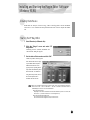
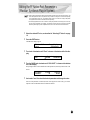
Starting the PF Easy Editor
1
Start XGworks (or XGworks lite).
2
Click the “Plug-in” menu and select “PF
Easy Editor.”
Alternately, press Alt + P, then D, and ENTER. The
“Select PF Part” dialog box appears.
3
Set the desired Part number and click “OK.”
The PF Easy Editor window appears.
If the PLG150-PF has been properly installed and all computer/
MIDI connections have been
properly made, operating the PF
Easy Editor should directly affect
the PLG150-PF. For details on
using the PF Easy Editor, refer to
the on-line help file that is
included with the software.
When using a Modular Synthesis Plug-in System “mother” device, the Part assignment depends on
which mode is used — Voice or Performance — and also on whether the PLG150-PF board is
installed/assigned to PLG1 or PLG2, as described below.
When using the Voice mode:
Depending on which slot the PLG150-PF board has been installed to, press PLG1 or PLG2, then
set the Part to “1” (no matter what the PLG1 or PLG2 assignment is).
When using the Performance (Multi) mode:
If the PLG150-PF board is assigned to PLG1, set the Part to “16.”
If the PLG150-PF board is assigned to PLG2, set the Part to “15.”
11
Selecting PF Voices
(Modular Synthesis Plug-in System)
When the PLG150-PF is installed to a CS6x Control Synthesizer, the PF voices can be selected in
the same way as the internal voices of the synthesizer.
The example displays used in the following explanations are all taken from the CS6x.
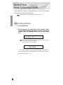
Enabling and Selecting PF Voices
1
Press the VOICE button.
2
Press the appropriate PLG button (PLG1 or PLG2, depending on which
slot the PLG150-PF board has been installed to), then press the appropriate BANK button and PROGRAM button to select the desired Plug-in
voice.
VCE Play) PLG1:001(A01)[PF:GndPnoSt ]
EQLow-G EQMid-G EQHi-G ------- ------To select a different bank, simultaneously hold down the appropriate PLG button and turn knob C (or
press the DEC/INC buttons) to select the desired bank.
The bank is expressed in two numbers: MSB and LSB.
VCE Play)
PLG1:001(A01)[PF:GndPnoSt
BANK= 080/000
]
If a selected bank is not available, the bank letter indication in the display (A - H) will not change.
For a list of the available banks and their MSB/LSB values, refer to the “PF-XG Voice Map” at
the back of this manual (pages 26 — 28).
12
Editing the PF Native Part Parameters
(Modular Synthesis Plug-in System)
●
●
Keep in mind that the parameter values and settings below represent offsets of the actual voice settings. This
means that adjustments made to the parameters may not make much change in the actual sound, depending
on the original settings of the voice. For parameter values, a setting of “0” results in no change, while positive
and negative values increase and decrease the value respectively.
The following explanations show how to edit the PF native part parameters when creating PLG voices, using
the CS6x Control Synthesizer as an example. For information on storing the PLG voices with your particular
Modular Synthesis Plug-in System compatible instrument, refer to the owner’s manual of that instrument.
1
Select the desired PF voice, as described in “Selecting PF Voices” on page
12.
2
Press the EDIT button.
The EDIT menu display appears.
GEN Name) Pf-Sq
Commom
3
0-? Cursor
[PF:GndPnoSt ]
Turn knob A clockwise until “Elem” is shown at the bottom left of the display.
PLG Assign)
Elem
4
a-Z
Bank
080/000
Number
1[GndPnoSt]
Turn the PAGE knob clockwise until “PLG150-PF” is shown at the bottom
left of the display.
Keep turning the knob to select the different PF Part parameters, indicated just above knob C and
knob 2.
NTV Param)
PLG150-PF
5
PF Mode
ON
SusCurve
Normal
Use knobs C and 2 to select the desired parameter and change the value.
Once one of the parameters is selected (the arrow cursor appears next to the value), you can also
adjust the value with the DATA knob or the DEC/INC buttons.
13
Selecting/Editing the PF System Parameters
(Modular Synthesis Plug-in System)
The example displays used in the following explanations are all taken from the CS6x.
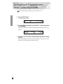
1
Press the UTILITY button.
The Utility Mode display appears.
MSTR TG)
Sys
2
Vol
64
NtShift
+ 0 +
Tune
0.0c
Turn the PAGE knob clockwise until “PLG150-PF” is shown at the bottom
left of the display.
Keep turning the knob to select the different PF System parameters, indicated just above knob C
and knob 2.
PLG1 MIDI)
PLG150-PF
3
PartAssign
01
VelCurve
Normal
Use knobs C and 2 to select the desired PF System parameter and change
the value.
Once one of the parameters is selected (the arrow cursor appears next to the value), you can also
adjust the value with the DATA knob or the DEC/INC buttons.
14
Selecting PF Voices (XG Plug-in System)
The PLG150-PF voices can be selected just like the voices of the XG tone generator. Keep in mind,
though, that they can only be selected when the Sound Module Mode is set to XG or Performance.
Also, the Part Assign parameter in the Utility mode (see below) must be set to the desired Part.
The example displays used in the following explanations are all taken from the MU128.
Enabling and Selecting PF Voices
1
Set the Sound Module Mode to “XG” or “PFM” (Performance).
Press the MODE button and use the SELECT </> buttons.
The Performance mode is not available on the SW1000XG.
2
Set the Part Assign parameter to the desired Part number.
To do this:
1) Press the UTIL button.
2) Select the “PLUGIN” menu (with the SELECT > button) and press ENTER.
3) Select the “PLG150-PF” menu if necessary (with the SELECT </> buttons), and press
ENTER.
4) Select the Part Assign parameter (with the SELECT < button), and use the VALUE -/+ buttons or dial to change the Part number.
The Part Assign range for the XG mode is 1 - 16 and “off”; for the Performance mode, it is 1 - 4 and
“off.”
Press the EXIT button to return to the Play mode.
This operation can also be quickly and conveniently done from the PF Easy Editor (in XGworks).
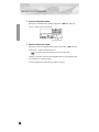
3
Enable the PLG150-PF board for the desired Part.
First, make sure that the appropriate Part is selected (using the PART -/+ buttons), then press the
SELECT button. The icon of the selected board appears in the display and the corresponding
LED at the bottom of the panel (PLG-1, -2, or -3) flashes briefly.
15
Selecting PF Voices (XG Plug-in System)
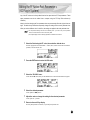
4
Select the desired bank number.
Move the cursor to the Bank Number parameter with the SELECT </> buttons and use the
VALUE -/+ buttons to select the desired bank.
Bank Number parameter
5
Select the desired voice number.
Move the cursor to the Voice (Program) Number parameter with the SELECT </> buttons and
use the VALUE -/+ buttons to select the desired voice.
Voices (and Voice banks) can also be selected by using the Voice Category buttons.
Alternately, you can select voices from a connected MIDI keyboard, or from sequencing software
(such as XGworks) on a connected computer.
For a list of available voices and their bank/voice numbers, see page 26.
16
Editing the PF Native Part Parameters
(XG Plug-in System)
Any of the PF voices can be freely edited from the front panel with the PF Part parameters. These
same parameters can also be edited from a computer using the PF Easy Editor software (in
XGworks).
Keep in mind that changing the Part parameters does not permanently affect the original voice settings. The edits that you make here temporarily change the settings of the currently selected voice.
When you select a different voice for the Part, the settings are applied to the newly selected voice.
●
●
1
The Part parameter settings cannot be saved in Multi Play mode. If you wish to save your Part parameter
edits, do it from the Performance mode or the PF Easy Editor.
The example displays used in the following explanations are all taken from the MU128.
Select the Part having the PF voice, then select the desired voice.
Select the appropriate Part with the PART -/+ buttons, then, with the cursor at the Voice Number
parameter, select the desired voice.
2
Press the EDIT button to enter the Edit mode.
3
Select the “PLUGIN” menu.
Use the SELECT > button, then press the ENTER button. The PLG150-PF Edit menu appears.
4
Select the desired parameter.
Use the [SELECT </>] buttons.
5
Adjust the value or change the setting for the selected parameter.
Use the [VALUE +/-] buttons.
6
Return to the main Play display.
Press the [EXIT] button several times, or press the [PLAY] button once.
17
Selecting/Editing the PF System Parameters
(XG Plug-in System)
The parameters that apply to the entire system of the PLG150-PF are included in the Utility mode
menu of the XG tone generator.
The example displays used in the following explanations are all taken from the MU128.
1
Press the [UTIL] button.
The Utility mode menu appears.
2
Select the “PLUGIN” menu.
Use the [SELECT >] button to highlight “PLUGIN,” then press the [ENTER] button.
3
Select the PLG150-PF board.
If the PLG150-PF board is the only one installed, “PLG150-PF” is already displayed and can be
selected by pressing the [ENTER] button. If additional boards have been installed to the tone
generator, you may need to select “PLG150-PF.” To do this, first use the [SELECT </>] buttons, then press [ENTER].
The System parameter menu for the PLG150-PF appears.
4
Select the desired parameter.
Use the [SELECT </>] buttons.
5
Adjust the value or change the setting for the selected parameter.
Use the [VALUE +/-] buttons.
6
Return to the main Play display.
Press the [EXIT] button several times, or press the [PLAY] button once.
18
Parameters
PF Native Part Parameters
Keep in mind that the parameter values and settings represent offsets of the actual voice settings. This
means that the actual sound that results from the settings made here depends on the original settings
of the voice.
Also keep in mind that these are “Part” parameters and as such, are temporary; they simply alter or
offset the settings of the currently selected voice. The original voice settings are permanently maintained in memory.
For parameter values, a setting of “0” results in no change, while positive and negative values increase
and decrease the value respectively.
Let’s look at a specific example. If the original Bass Frequency parameter of the selected voice is set
to 100, and you set the Bass Frequency (below) to “-25,” the actual Bass Frequency will become “75.”
If you set it to “+10,” the value will become “110.” Naturally, this also means that the parameter
value cannot be increased or decreased beyond its maximum or minimum values. In our example,
Bass Frequency values higher than “+27” have no effect on the sound, since the actual range is 0 —
127.
●
●
Depending on the selected voice and the particular parameter being edited, the sound or actual
parameter value of certain voices may change very little or not at all, even when the parameter
value is changed drastically.
For Modular Synthesis Plug-in System compatible devices, the voices you edit/create can be stored
to the device as PLG voices. For details on storing voices, refer to the owner’s manual of your Modular Synthesis Plug-in System compatible instrument.
■ PF Mode
Settings: ON, OFF
This determines whether the PF (Piano) Mode is on or off. When this is set to “ON” and damper (sustain) pedal messages are received, the PLG150-PF simulates the sound of a damper pedal.
■ SusCurve (Sustain Curve)
Settings: Normal, Step
This determines how the voices respond to damper (sustain) pedal messages. When this is set to
“Normal,” the PLG150-PF simulates the actual damper pedal action of an acoustic piano, giving you
continuous control over sustain. When this is set to “Step,” sustain is simply turned on or off in
response to damper pedal messages.
19
Parameters
■ Bass Freq (Bass Frequency)
Range: -64 — +00 — +63
This determines the frequency which is boosted or cut (in the Bass Gain parameter below) for each
Part.
■ Bass Gain
Range: -64 — +00 — +63
This determines the level of the selected frequency (in “Bass Freq” above). Positive values boost the
level of the selected frequency and negative values attenuate it.
■ Treble Freq (Treble Frequency)
Range: -64 — +00 — +63
This determines the frequency which is boosted or cut (in the Treble Gain parameter below) for each
Part.
■ Treble Gain
Range: -64 — +00 — +63
This determines the level of the selected frequency (in “Treble Freq” above). Positive values boost the
level of the selected frequency and negative values attenuate it.
■
■
■
■
EL1 Level (Element 1 Level)
EL2 Level (Element 2 Level)
EL3 Level (Element 3 Level)
EL4 Level (Element 4 Level)
Range: -64 — +00 — +63 (“***”: not available)
The voices of the PLG150-PF are made up of one to four sound elements. More sophisticated sounds
have more elements. Though these elements are fixed for the various sounds and cannot be changed,
the volume of each element can be set and adjusted. These parameters determine the level of each
corresponding element. (Elements that are not used by the voice cannot be set here and are indicated
by “***” in the display.)
20
Parameters
■
■
■
■
AC1 EL1 Lev (Assignable Controller 1 — Element 1 Level Control)
AC1 EL2 Lev (Assignable Controller 1 — Element 2 Level Control)
AC1 EL3 Lev (Assignable Controller 1 — Element 3 Level Control)
AC1 EL4 Lev (Assignable Controller 1 — Element 4 Level Control)
Range: -64 — +00 — +63 (“***”: not available)
As explained in EL1 - EL4 Level above, the voices of the PLG150-PF are made up of up to four sound
elements. These parameters determine the degree to which the Assignable Controller 1 (AC1) is used
to control the level of each corresponding element. (Elements that are not used by the voice cannot be
set here and are indicated by “***” in the display.) Positive values result in normal level control: Moving
the controller toward the maximum settings increases the level. Negative values result in an inverse
relationship: Moving the controller toward the maximum settings decreases the level. A value of “0”
results in no control.
■ REV Send (Reverb Send)
Range: -127 — +127 (“****”: not available)
This determines the amount of voice signal that is sent to the PLG150-PF’s built-in Reverb effect.
■ CHO Send (Chorus Send)
Range: -127 — +127 (“****”: not available)
This determines the amount of voice signal that is sent to the PLG150-PF’s built-in Chorus effect.
■ INS LFOFrq (Insertion LFO Frequency)
Range: -127 — +127 (“****”: not available)
This determines the frequency of LFO modulation for the PLG150-PF’s built-in Insertion effect.
■ INS LFODpt (Insertion LFO Depth)
Range: -127 — +127 (“****”: not available)
This determines the depth of LFO modulation for the PLG150-PF’s built-in Insertion effect.
■ INS Feedback (Insertion Feedback Level)
Range: -127 — +127 (“***”: not available)
This determines the feedback level for the PLG150-PF’s built-in Insertion effect.
21
Parameters
■ INS DryWet (Insertion Dry/Wet Balance)
Range: -127 — +127 (“****”: not available)
This determines the balance between the direct, unprocessed signal (dry) and the Insertion-processed
sound (wet).
■ INS Offset (Insertion Offset)
Range: -64 — +63 (“****”: not available)
This parameter is used to change one specific parameter of the effect; the particular parameter
depends on the effect type.
■ INS Drive (Insertion Drive)
Range: -127 — +127 (“****”: not available)
This determines the amount of distortion overdrive for the PLG150-PF’s built-in Insertion effect.
■ INS ClpCrv (Insertion Clipping Curve)
Range: -127 — +127 (“****”: not available)
This determines the amount of distortion “edge” for the PLG150-PF’s built-in Insertion effect. Higher
values result in harder edged distortion.
■ INS Delay (Insertion Delay Time)
Range: -7149 — +7149 (“*****”: not available)
This determines the delay time for the PLG150-PF’s built-in Insertion effect.
●
●
22
Keep in mind that these parameters are offset controls; the actual resulting effect sound will differ
from voice to voice. If the currently selected voice does not have any effect or uses an effect type
not corresponding to this parameter, the parameter is unavailable and is indicated by asterisks
("***") in the display.
Whether this Insertion effect parameter is available or not depends on the selected voice and its
pre-assigned Insertion effect types. (For details on the effect types and parameters for each voice,
see the Preset Voice List on page 24 and the Effect Parameter List on page 30.)
Parameters
PF System Parameters
■ Part Assign
Settings: 01 — 16, off
This determines the Part to which the PLG150-PF voice is assigned. If a Part is not properly assigned
here, none of the PLG150-PF voices can be selected for the Part. (This applies to XG Plug-in System
compatible “mother” devices.)
The PLG150-PF voices can only be assigned to a single Part.
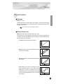
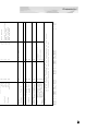
■ VelCurve (Velocity Curve)
Settings: Normal, Soft1, Soft2, Soft3, Hard1, Hard2, Cross1, Cross2
This function lets you to produce determine how the volume of the PLG150-PF's Voices respond to
your playing touch (velocity). Eight different Velocity Curve settings (or curves) are available, letting you
tailor the response to your own preference.
●
The Normal setting provides standard touch response.
●
Soft 1 to 3 allow you to produce a reasonably high volume with a
soft, light touch (low velocities).
●
Hard 1 and 2 produce high volume only with a hard, strong touch
(high velocities).
●
Cross 1 and 2 are “mirror image” curves, designed to be used
together with different voices in a layer to produce a velocity
crossfade effect. As shown in the illustration, the two curves
complement each other in a way that allows the Cross 2 applied
voice to sound at soft velocities, while the Cross 1 voice sounds
at high velocities.
23
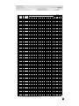
Appen-
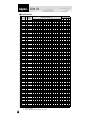
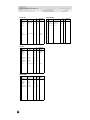
Voice List
■ Preset Voice List
No. Voice Name E
1
2
3
4
5
6
7
8
9
10
11
12
13
14
15
16
StGndPSt
GndPnoSt
BrghtGnd
60'sGrnd
StRichSt
RchGndSt
60'sJazz
StTghtSt
TghtGdSt
PowerGnd
MildGrnd
Timeworn
ChorusMn
Doom
Phono
Room
2
2
2
1
2
2
2
2
1
2
2
1
1
1
1
1
17
18
19
20
21
22
23
24
25
26
27
28
29
30
31
32
33
34
35
36
37
38
39
40
41
42
43
44
45
46
47
48
49
50
51
52
53
54
55
56
57
58
59
60
61
62
63
64
AmbiGrnd
FlngGrnd
CelesGnd
Dbl Pno
Montuno
GrndDyno
David
RhodyGnd
Perc Pno
GrandDX
GrandDX2
Bob
PianoStr
PnoStPad
SynStrPf
PianoPad
OctPf+Pd
Pf+Choir
ModPd Pf
Pia-Tron
SitaryPf
BrghtPno
Digital
ChorDigi
Grnd+EP
DigiGrnd
Grnd/wDX
ChoDigiP
GlassPno
DigiTine
CP
CP-Symph
Trem CP
BrightCP
Digi CP1
Digi CP2
Jino
Petit CP
Hnkytnk1
Hnkytnk2
Hnkytnk3
FMHkytnk
Tea
Deodar
70's EP
80's EP
Crisp EP
Sweetnes
2
2
1
2
3
3
4
3
4
3
3
4
4
4
3
4
4
3
4
3
4
1
1
1
3
1
4
3
3
3
1
1
1
2
2
3
3
2
2
2
2
2
1
1
1
1
1
1
Insertion
Effect Type
2 Band EQ
2 Band EQ
2 Band EQ
3 Band EQ
2 Band EQ
2 Band EQ
2 Band EQ
2 Band EQ
2 Band EQ
2 Band EQ
2 Band EQ
Chorus
Reverse Gate
Distortion
ER
Cross Delay
Flanger
Celeste
1
28
28
28
70
28
28
21
28
28
28
32
2
69
69
69
44
69
69
52
67
67
67
66
3
46
46
52
76
49
49
28
46
46
46
56
4
68
68
74
81
76
76
76
73
73
76
52
5
1
2
1
54
19
20
19
77
8
60
5
106
3
34
16
1700 1750
6
46
3
32
104
104
64
1
2
0
2 Band EQ
2 Band EQ
Chorus
28
28
5
64
68
54
46
46
102
66
68
106
2 Band EQ
Symphonic
Auto Pan
Chorus
28
4
34
6
68
25
80
54
46
16
24
77
69
0
55
3 Band EQ
3 Band EQ
3 Band EQ
3 Band EQ
2 Band EQ
2 Band EQ
2 Band EQ
2 Band EQ
3 Band EQ
Phaser
58
64
60
60
28
28
28
28
61
8
34
34
34
34
64
67
63
64
34
111
52
64
64
59
46
46
46
46
62
11
10
10
10
10
70
70
68
64
10
91
Insertion Effect Parameter No. (*1)
5
6
7
8
9
10 11
59
64
75
64
28
46
28
0
67
47
43
46
0
46
76
13
14
71
10
15
16
0
3
0
10
10
28
28
68
64
46
46
76
70
35
96
68
28
64
46
66
46
0
28
28
28
63
66
64
46
46
46
67 127
69
64 32
0
68
64
63
67
28
28
28
28
46
46
46
46
69
28
28
46
60
58
64
E : Numbers of elements
(*1) : Refer to “PLG150-PF Voice Effect Parameter List” (page 30).
24
39
30
6
10 127 120
37
5
12
64
28
67
4
58
1
3
1
67
Voice EQ
Bass Bass Treble Treble
Freq Gain Freq Gain
9
64
52
64
9
64
52
64
9
64
58
76
9
64
52
64
9
69
52
70
9
69
52
70
30
67
49
56
9
69
52
68
9
69
52
68
9
76
52
73
9
64
47
73
5
68
54
53
9
64
52
64
9
76
52
84
9
64
52
64
14
71
52
72
9
9
9
9
9
13
9
9
22
16
16
9
13
13
9
13
9
9
9
19
9
9
9
9
13
9
16
15
9
14
9
9
9
13
9
4
9
9
9
9
9
9
9
9
9
9
9
9
64
64
70
64
66
74
64
70
58
72
66
66
72
72
64
72
70
64
70
55
70
64
64
64
71
54
72
58
60
62
67
64
69
60
64
68
50
70
68
64
64
64
64
64
64
64
64
63
52
52
52
52
45
51
52
52
52
50
50
52
52
52
48
52
45
48
45
52
48
52
52
52
51
41
50
52
58
42
52
52
52
51
52
58
52
45
52
52
52
52
52
52
52
52
52
52
64
64
71
64
70
69
71
75
70
68
68
71
69
69
79
69
67
65
69
6
70
64
64
64
73
52
68
64
84
64
68
64
71
69
64
64
68
67
64
64
64
64
68
64
64
64
64
73
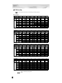
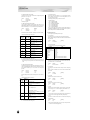
Voice List
No. Voice Name E
65
66
67
68
69
70
71
72
73
74
75
76
77
78
79
80
Freeway
Trem 70
Remark
Sample
Mid 70's
Celest80
At Once
TremDyno
TremWurl
Phase 70
DlydDyno
FlngDyno
Dstrtd70
Dyno 81
Tonight
Dyno 83
1
1
1
1
1
1
2
1
1
1
1
1
1
1
1
1
81
82
83
84
85
86
87
88
89
90
91
92
93
94
95
96
97
98
99
100
101
102
103
104
105
106
107
108
109
110
111
112
113
114
115
116
117
118
119
120
121
122
123
124
125
126
127
128
Dbl 70's
Digi-Rho
Choir EP
Paddy EP
VcePd EP
Vibrt EP
60's EP
Trump
DonnyWrl
WurliAmp
Dg Wurli
FullTine
DX EP2
DX 1980
DX 1990
Mllw DX
ChrsTine
Chrs EP2
Chrs1980
Chrs1990
DarkDXEP
FTBallad
Sym EP2
Chrs1982
90Ballad
816
DXEP+Pad
DXSynStr
DXEP+Cho
Balmy DX
GlassyEP
FM Piano
Chrs FMP
Harpsi 1
Harpsi 2
Harpsi 3
Harpsi 4
RichHpsi
ShrpHpsi
Clav 1
Clav 2
MuteClav
Phs Clav
PhsClav2
Wah Clav
DigiClav
Ch DgClv
PhsDgClv
2
3
2
2
3
3
1
1
1
1
2
1
1
1
1
3
1
1
1
1
2
1
1
1
1
4
3
3
3
3
4
1
1
1
2
1
2
1
2
1
1
1
1
1
1
1
1
1
Insertion
Effect Type
Auto Pan
Auto Pan
Phaser
Rotary SP
Chorus
Celeste
Symphonic
Auto Pan
Tremolo
Phaser
Delay L,C,R
Flanger
Amp Simulator
Celeste
ER
1
2
3
4
53 127
0
5
48
80
32
5
60
31
71
90
29
30
6
39
77
57
12
13
64
0
12
14
58
47
80
32
5
83
39
0
36 111
74 104
3333 1667 5000 5000
14
15
84
2
4
0
60 127
8
0
32
19
64
5
0
16
Voice EQ
Insertion Effect Parameter No. (*1)
Bass Bass Treble Treble
5
6
7
8
9
10 11 12 13 14 15 16 Freq Gain Freq Gain
28 64 46 67
9
67
52
72
28 64 46 65
9
67
52
72
23 64 46 72 110
8
0
9
64
52
69
24 59 45 65 127
39
53
52
70
28 59 46 67 34
0
9
64
52
64
28 62 46 66 61
1
9
64
52
64
28 62 48 73 61
9
64
52
64
28 60 45 69
9
64
52
64
28 61 46 66
64
0
9
64
52
72
28 61 46 68 64
6
1
9
64
52
64
74 100 10
32
28 64 58 67
9
58
52
68
28 55 46 67 59
4
9
64
52
69
29 26
9
64
52
69
9
51
52
64
28 60 52 67 59
0
9
55
52
64
64
0 46
25
5
0 10
9
67
41
93
2 Band EQ
Amp Simulator
28
3
62
3
46
48
65
105
127
42
Amp Simulator
3
3
48
108
127
56
28
28
28
28
62
63
61
64
46
46
46
46
64
68
67
65
6
6
6
6
34
38
54
54
77
77
77
77
78
64
85
53
Symphonic
Symphonic
3 Band EQ
Symphonic
12
9
60
10
25
25
34
25
16
16
52
16
Celeste
12
32
64
Chorus
6
54
3 Band EQ
3 Band EQ
Reverse Gate
3 Band EQ
3 Band EQ
3 Band EQ
3 Band EQ
3 Band EQ
Phaser
Phaser
Auto Wah
58
64
1
60
58
64
64
64
14
8
70
Chorus
Phaser
6
17
2 Band EQ
2 Band EQ
2 Band EQ
2 Band EQ
Chorus
Chorus
Chorus
Chorus
28
28
28
28
61
61
60
60
46
46
46
46
67
68
68
67
64
64
39
37
28
28
28
28
60
60
46
60
46
46
69
66
40
55
46
67
47
0
28
61
46
64
39
0
77
74
28
61
46
67
48
0
34
28
7
34
34
45
34
34
127
111
33
64
76
8
52
52
67
64
68
69
127
56
10
120
3
10
10
10
10
10
24
104
49
28
28
0
28
28
28
28
28
28
28
28
46
46
47
46
46
46
46
46
66
62
69
54
111
77
74
17
104
28
28
62
62
10
64
69
64
64
64
72
70
71
64
0
0
0
0
36
6
3
46
46
46
67 127
64 127
71 127
6
6
0
0
46
46
66
66
10
1
37
64
10
0
9
9
9
7
9
12
9
9
8
9
12
9
9
9
9
12
9
9
9
9
12
9
9
9
9
9
13
13
13
15
4
9
9
16
9
40
9
16
9
9
9
9
9
9
9
17
17
17
64
65
70
66
70
70
64
64
72
64
69
64
64
64
64
69
64
64
64
64
69
66
64
64
62
54
68
68
68
53
74
64
64
70
64
65
64
70
64
64
64
64
64
64
64
68
68
68
52
50
45
56
45
48
52
50
53
50
52
52
52
52
52
52
52
52
52
52
52
52
52
52
52
52
52
52
52
36
54
52
52
52
52
52
52
52
52
52
52
52
52
52
52
52
52
52
64
66
67
68
69
68
68
71
74
71
70
70
64
64
64
67
73
64
64
64
71
68
64
67
66
68
67
67
67
58
75
64
64
68
64
68
64
72
64
64
64
84
69
75
86
68
72
68
E : Numbers of elements
(*1) : Refer to “PLG150-PF Voice Effect Parameter List” (page 30).
25
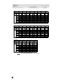
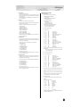
Voice List
■ PF-XG Voice Map
Voices having the same name also have the same effect types and settings. (Page 24)
● PF-XG/A Bank
Bank Select MSB
80
80
80
80
80
80
80
Bank Select LSB
0
64
65
66
67
68
69
Instrument
Group
Pgm#
(1-128)
Piano
E
E
E
E
E
E
E
1 GndPnoSt
2
GndPnoMn
1
BrghtGnd
2
60'sGrnd
1
RchGndSt
2
RchGndMn
2
60'sJazz
2
TghtGdSt
1
2 BrghtPno
1
Digital
1
ChorDigi
1
Grnd+EP
3
DigiGrnd
1
Grnd/wDX
4
ChoDigiP
3
GlassPno
3
3 CP
1
CP-Symph
1
Trem CP
1
BrightCP
2
Digi CP1
2
Jino
3
Digi CP2
3
Petit CP
2
4 Hnkytnk1
2
Hnkytnk2
2
Hnkytnk3
2
FMHkytnk
2
5 Tea
1
Deodar
1
70's EP
1
80's EP
1
Crisp EP
1
Sweetnes
1
Freeway
1
Trem 70
1
6 FullTine
1
DX EP2
1
DX 1980
1
DX 1990
1
Mllw DX
3
ChrsTine
1
Chrs EP2
1
Chrs1980
1
7 Harpsi 1
1
Harpsi 2
2
Harpsi 3
1
Harpsi 4
2
RichHpsi
1
ShrpHpsi
2
8 Clav 1
1
Clav 2
1
MuteClav
1
Phs Clav
1
PhsClav2
1
Wah Clav
1
DigiClav
1
Ch DgClv
1
80
80
80
80
80
80
80
Bank Select LSB
71
72
73
74
75
76
77
Pgm#
(1-128)
Piano
70
E
Bank Select MSB
Instrument
Group
80
E
E
E
E
Timeworn
1
E
ChorusMn
1
E
Doom
1
80
78
E
Phono
1
E
1 TghtGdMn
2
PowerGnd
2
MildGrnd
2
2 DigiTine
3
SawDigi1
2
SawDigi2
2
Room
1
5 Remark
1
Sample
1
Mid 70's
1
Celest80
1
At Once
2
TremDyno
1
TremWurl
1
Phase 70
1
6 Chrs1990
1
DarkDXEP
2
FTBallad
1
Sym EP2
1
Chrs1982
1
90Ballad
1
816
4
DXEP+Pad
3
3
4
7
8 PhsDgClv
1
Bank Select MSB
80
80
80
80
80
80
80
Bank Select LSB
79
80
81
82
83
84
85
Instrument
Group
Pgm#
(1-128)
Piano
E
1 AmbiGrnd
E
E
E
E
E
80
86
E
E
2
FlngGrnd
2
CelesGnd
1
Dbl Pno
2
Montuno
3
GrndDyno
3
David
4
RhodyGnd
3
5 DlydDyno
1
FlngDyno
1
Dstrtd70
1
Dyno 81
1
Tonight
1
Dyno 83
1
Dbl 70's
2
Digi-Rho
3
6 DXSynStr
3
DXEP+Cho
3
Balmy DX
3
GlassyEP
4
FM Piano
1
Chrs FMP1
1
2
3
4
7
8
Bank Select MSB
80
80
80
80
80
80
80
Bank Select LSB
87
88
89
90
91
92
93
Instrument
Group
Piano
Pgm#
(1-128)
E
1 Perc Pno
E
E
E
E
E
80
94
E
E
4
GrandDX
3
GrandDX2
3
Bob
4
PianoStr
4
PnoStPad
4
SynStrPf
3
PianoPad
4
2
Paddy EP
2
VcePd EP
3
Vibrt EP
3
60's EP
1
Trump
1
DonnyWrl
1
WurliAmp
1
2
3
4
5 Choir EP
6
7
8
E : Number of simultaneously sounding elements.
: Silence
26
Voice List
Bank Select MSB
80
80
80
80
80
80
80
80
Bank Select LSB
95
96
97
98
99
100
101
102
Instrument
Group
Pgm#
(1-128)
Piano
E
1 OctPf+Pd
4
E
Pf+Choir
3
E
ModPd Pf
4
E
Pia-Tron
3
E
SitaryPf
4
E
StGndPSt
2
E
StGndPMn
1
E
StRichSt
2
2
3
4
5 Dg Wurli
2
6
7
8
Bank Select MSB
80
80
80
Bank Select LSB
103
104
105
Instrument
Group
Pgm#
(1-128)
Piano
E
1 StRichMn
1
E
StTghtSt
2
E
StTghtMn
1
2
3
4
5
6
7
8
E : Number of simultaneously sounding elements.
: Silence
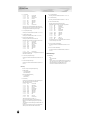
● PF-XG/B Bank
Bank Select MSB
96
96
96
96
96
96
96
Bank Select LSB
0
64
65
66
67
68
69
Instrument
Group
Pgm#
(1-128)
Piano
E
E
E
E
E
E
E
1 GndPnoSt
2
GndPnoMn
1
BrghtGnd
2
60'sGrnd
1
RchGndSt
2
RchGndMn
2
60'sJazz
2
TghtGdSt
1
2 BrghtPno
1
Digital
1
ChorDigi
1
Grnd+EP
3
DigiGrnd
1
Grnd/wDX
4
ChoDigiP
3
GlassPno
3
3 CP
1
CP-Symph
1
Trem CP
1
BrightCP
2
Digi CP1
2
Jino
3
Digi CP2
3
Petit CP
2
4 Hnkytnk1
2
Hnkytnk2
2
Hnkytnk3
2
FMHkytnk
2
5 Tea
1
Deodar
1
70's EP
1
80's EP
1
Crisp EP
1
Sweetnes
1
Freeway
1
Trem 70
1
6 FullTine
1
DX EP2
1
DX 1980
1
DX 1990
1
Mllw DX
3
ChrsTine
1
Chrs EP2
1
Chrs1980
1
7 Harpsi 1
1
Harpsi 2
2
Harpsi 3
1
Harpsi 4
2
RichHpsi
1
ShrpHpsi
2
8 Clav 1
1
Clav 2
1
MuteClav
1
Phs Clav
1
PhsClav2
1
Wah Clav
1
DigiClav
1
Ch DgClv
1
96
96
96
96
96
96
96
Bank Select LSB
71
72
73
74
75
76
77
Piano
70
E
Bank Select MSB
Instrument
Group
96
Pgm#
(1-128)
E
E
E
E
Timeworn
1
E
ChorusMn
1
E
Doom
1
96
78
E
Phono
1
E
1 TghtGdMn
2
PowerGnd
2
MildGrnd
2
2 DigiTine
3
SawDigi1
2
SawDigi2
2
Room
1
5 Remark
1
Sample
1
Mid 70's
1
Celest80
1
At Once
2
TremDyno
1
TremWurl
1
Phase 70
1
6 Chrs1990
1
DarkDXEP
2
FTBallad
1
Sym EP2
1
Chrs1982
1
90Ballad
1
816
4
DXEP+Pad
3
3
4
7
8 PhsDgClv
1
E : Number of simultaneously sounding elements.
: Refer to the XG Voice List (MSB=0) of the XG Plug-in System “mother” device.
27
Voice List
Bank Select MSB
96
96
96
96
96
96
96
Bank Select LSB
79
80
81
82
83
84
85
Instrument
Group
Pgm#
(1-128)
Piano
E
1 AmbiGrnd
E
E
E
E
E
96
86
E
E
2
FlngGrnd
2
CelesGnd
1
Dbl Pno
2
Montuno
3
GrndDyno
3
David
4
RhodyGnd
3
5 DlydDyno
1
FlngDyno
1
Dstrtd70
1
Dyno 81
1
Tonight
1
Dyno 83
1
Dbl 70's
2
Digi-Rho
3
6 DXSynStr
3
DXEP+Cho
3
Balmy DX
3
GlassyEP
4
FM Piano
1
Chrs FMP1
1
2
3
4
7
8
Bank Select MSB
96
96
96
96
96
96
96
Bank Select LSB
87
88
89
90
91
92
93
Instrument
Group
Pgm#
(1-128)
Piano
E
1 Perc Pno
E
E
E
E
E
96
94
E
E
4
GrandDX
3
GrandDX2
3
Bob
4
PianoStr
4
PnoStPad
4
SynStrPf
3
PianoPad
4
2
Paddy EP
2
VcePd EP
3
Vibrt EP
3
60's EP
1
Trump
1
DonnyWrl
1
WurliAmp
1
2
3
4
5 Choir EP
6
7
8
Bank Select MSB
96
96
96
96
Bank Select LSB
95
96
97
98
Instrument
Group
Piano
Pgm#
(1-128)
E
1 OctPf+Pd
4
E
Pf+Choir
3
E
ModPd Pf
4
96
99
E
Pia-Tron
3
E
SitaryPf
4
2
3
4
5 Dg Wurli
2
6
7
8
E : Number of simultaneously sounding elements.
: Refer to the XG Voice List (MSB=0) of the XG Plug-in System “mother” device.
28
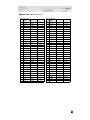
Voice List
■ Plug-in Voice List (for CS6x, CS6R, S80)
Program Plug-in Voice
No.
Name
KNOB1
KNOB2
Program Plug-in Voice
Name
No.
KNOB1
KNOB2
1 StrchGndPf
Reverb Send
33 Crisp EP
Reverb Send
2 StrchRichP
Reverb Send
34 Sweetness
Phaser Depth
Comp Threshold
Chorus Send
3 StrchTghtP
Reverb Send
35 Freeway
AutoPan L/RDpth
AutoPan Speed
4 BrghtGrand
Reverb Send
36 Remark
Phaser Depth
Phaser Speed
5 60's Grand
Reverb Send
37 Sample
Reverb Send
Chorus Send
6 60's Jazz
Reverb Send
38 At Once
Reverb Send
Chorus Send
7 Timeworn
Reverb Send
39 TremroDyno
AutoPan L/RDpth
AutoPan Speed
8 ChorusMono
Reverb Send
Chorus Send
40 Phase 70
Phaser Depth
Phaser Speed
9 Phono
Reverb Send
Distortion Drive
41 Dyno 81
Reverb Send
Comp Ratio
10 GrandDyno
Reverb Send
Chorus Send
42 Tonight
Reverb Send
Celeste Depth
11 RhodyGrand
Reverb Send
Chorus Send
43 Digi-Rho
Reverb Send
Chorus Send
12 Perc Piano
Reverb Send
Chorus Send
44 Choir EP
Reverb Send
Chorus Send
13 Grand DX
Reverb Send
Chorus Send
45 Paddy EP
Reverb Send
Chorus Send
14 Bob
Reverb Send
Chorus Send
46 VcePd EP
Reverb Send
15 Grand+EP
Reverb Send
Chorus Send
47 60's EP
Reverb Send
Chorus Send
16 GlassPiano
Reverb Send
Chorus Send
48 Wurli Amp
Reverb Send
AmpSimulator Drive
17 PianoStrng
Reverb Send
49 Digi Wurli
Reverb Send
Chorus Send
18 SynthStrPf
Reverb Send
50 FullTine
Reverb Send
Chorus Send
19 Pia-Tron
Reverb Send
51 DX EP
Reverb Send
Chorus Send
20 BrghtPiano
Reverb Send
Chorus Send
21 ChoDigiP
Reverb Send
22 CP
Reverb Send
23 Bright CP
Reverb Send
24 Jino
Reverb Send
25 Digital CP
Reverb Send
26 Petit CP
Reverb Send
27 Honkytonk
Reverb Send
28 FMHonkytnk
Reverb Send
29 Tea
Comp Threshold
Chorus Send
30 Deodar
Comp Threshold
Chorus Send
62 PhaserClav
Phaser FBLevel
31 70's EP
Reverb Send
Chorus Send
63 Wah Clavi
AutoWah Speed
AutoWah Reso
32 80's EP
Reverb Send
Chorus Send
64 ChoDigiClv
Reverb Send
Chorus Send
Chorus Send
Chorus Send
Chorus Send
Chorus Send
52 DX 1980
Reverb Send
53 DX 1990
Reverb Send
Chorus Send
54 Mellow DX
Reverb Send
Chorus Send
55 816
Reverb Send
Chorus Send
56 DXSynStr
Reverb Send
Celeste Depth
57 Glassy EP
Reverb Send
Chorus Send
58 FM Piano
Reverb Send
Chorus Send
59 Rich Hpsi
Reverb Send
60 Octv Hpsi
Reverb Send
61 Clavi
Reverb Send
Phaser Speed
29
PLG150-PF Voice Effect Parameter List
(*1) PF Native Part Param : This parameter can control the Voice Effect.
DELAY L,C,R
No.
1
2
3
4
5
6
7
8
9
10
11
12
13
14
15
16
GATE REVERB / REVERSE GATE
Lch Delay
Rch Delay
Cch Delay
Feedback Delay
Feedback Level
Cch Level
High Damp
0.1 – 715.0ms
0.1 – 715.0ms
0.1 – 715.0ms
0.1 – 715.0ms
-63 – +63
0 – 127
0.1 – 1.0
Value See
Table
1-7150
1-7150
1-7150
1-7150
1-127
0-127
1-10
Dry/Wet
D63>W – D=W – D<W63
1-127
EQ Low Frequency
EQ Low Gain
EQ High Frequency
EQ High Gain
50Hz – 2.0kHz
-12 – +12dB
500Hz – 16.0kHz
-12 – +12dB
8-40
52-76
28-58
52-76
Parameter
Display
PF Native Part
Param
INS Delay Time
INS Delay Time
INS Delay Time
INS Delay Time
INS Feedback
INS DryWet
table#3
table#3
CROSS DELAY
No.
1
2
3
4
5
6
7
8
9
10
11
12
13
14
15
16
Parameter
L->R Delay
R->L Delay
Feedback Level
Input Select
High Damp
0.1 – 355.0ms
0.1 – 355.0ms
-63 – +63
L,R,L&R
0.1 – 1.0
Value See
Table
1-3550
1-3550
1-127
0-2
1-10
Dry/Wet
D63>W – D=W – D<W63
1-127
EQ Low Frequency
EQ Low Gain
EQ High Frequency
EQ High Gain
50Hz – 2.0kHz
-12 – +12dB
500Hz – 16.0kHz
-12 – +12dB
8-40
52-76
28-58
52-76
1
2
3
4
5
6
7
8
9
10
11
12
13
14
15
16
30
Parameter
Type
Room Size
Diffusion
Initial Delay
Feedback Level
HPF Cutoff
LPF Cutoff
Dry/Wet
Liveness
Density
High Damp
1
2
3
4
5
6
7
8
9
10
11
12
13
14
15
16
Type
Room Size
Diffusion
Initial Delay
Feedback Level
HPF Cutoff
LPF Cutoff
TypeA,TypeB
0.1 – 7.0
0 – 10
0.1 – 99.3ms
-63 – +63
Thru – 8.0kHz
1.0k – Thru
Value See
Table
0-1
0-44
table#5
0-10
0-63
table#4
1-127
0-52
table#3
34-60 table#3
Dry/Wet
Liveness
Density
High Damp
D63>W – D=W – D<W63
0 – 10
0–3
0.1 – 1.0
1-127
0-10
0-3
1-10
INS DryWet
PF Native Part
Param
INS LFO Freq
INS LFO Depth
INS Feedback
INS Offset
INS DryWet
Parameter
Display
PF Native Part
Param
INS Feedback
CHORUS1,2,3,4 / CELESTE1,2,3,4
Display
PF Native Part
Param
INS Delay Time
INS Delay Time
INS Feedback
INS DryWet
table#3
table#3
EARLY REF1,EARLY REF2
No.
No.
1
2
3
4
5
6
7
8
9
10
11
12
13
14
15
16
LFO Frequency
LFO Depth
Feedback Level
Delay Offset
0.00Hz – 39.7Hz
0 – 127
-63 – +63
0.0 – 50
Value See
Table
0-127 table#1
0-127
1-127
0-127 table#2
EQ Low Frequency
EQ Low Gain
EQ High Frequency
EQ High Gain
Dry/Wet
50Hz – 2.0kHz
-12 – +12dB
500Hz – 16.0kHz
-12 – +12dB
D63>W – D=W – D<W63
8-40
52-76
28-58
52-76
1-127
Input Mode
mono/stereo
0-1
Parameter
Display
table#3
table#3
FLANGER1,2,3
Display
Value See
Table
S-H, L-H, Rdm, Rvs, Plt, Spr 0-5
0.1 – 7.0
0-44
table#5
0 – 10
0-10
0.1 – 99.3ms
0-63
table#4
-63 – +63
1-127
Thru – 8.0kHz
0-52
table#3
1.0k – Thru
34-60 table#3
D63>W – D=W – D<W63
0 – 10
0–3
0.1 – 1.0
No.
1-127
0-10
0-3
1-10
PF Native Part
Param
INS Feedback
INS DryWet
No.
1
2
3
4
5
6
7
8
9
10
11
12
13
14
15
16
LFO Frequency
LFO Depth
Feedback Level
Delay Offset
0.00Hz – 39.7Hz
0 – 127
-63 – +63
0 – 63
Value See
Table
0-127 table#1
0-127
1-127
0-63
table#2
EQ Low Frequency
EQ Low Gain
EQ High Frequency
EQ High Gain
Dry/Wet
50Hz – 2.0kHz
-12 – +12dB
500Hz – 16.0kHz
-12 – +12dB
D63>W – D=W – D<W63
8-40
52-76
28-58
52-76
1-127
table#3
LFO Phase
Difference
-180 – +180deg
4-124
resolution=3deg.
Parameter
Display
PF Native Part
Param
INS LFO Freq
INS LFO Depth
INS Feedback
INS Offset
INS DryWet
table#3
PLG150-PF Voice Effect Parameter List
SYMPHONIC
No.
1
2
3
4
5
6
7
8
9
10
11
12
13
14
15
16
AUTO PAN
LFO Frequency
LFO Depth
Delay Offset
0.00Hz – 39.7Hz
0 – 127
0.0 – 50
Value See
Table
0-127 table#1
0-127
0-127 table#2
EQ Low Frequency
EQ Low Gain
EQ High Frequency
EQ High Gain
Dry/Wet
50Hz – 2.0kHz
-12 – +12dB
500Hz – 16.0kHz
-12 – +12dB
D63>W – D=W – D<W63
8-40
52-76
28-58
52-76
1-127
Parameter
Display
PF Native Part
Param
INS LFO Freq
INS LFO Depth
INS Offset
table#3
table#3
INS DryWet
1
2
3
4
5
6
7
8
9
10
11
12
13
14
15
16
LFO Frequency
LFO Depth
0.00Hz – 39.7Hz
0 – 127
Value See
Table
0-127 table#1
0-127
EQ Low Frequency
EQ Low Gain
EQ High Frequency
EQ High Gain
Dry/Wet
50Hz – 2.0kHz
-12 – +12dB
500Hz – 16.0kHz
-12 – +12dB
D63>W – D=W – D<W63
8-40
52-76
28-58
52-76
1-127
Parameter
Display
PF Native Part
Param
INS LFO Freq
INS LFO Depth
table#3
table#3
INS DryWet
TREMOLO
No.
1
2
3
4
5
6
7
8
9
10
11
12
13
14
LFO Frequency
AM Depth
PM Depth
0.00Hz – 39.7Hz
0 – 127
0 – 127
EQ Low Frequency
EQ Low Gain
EQ High Frequency
EQ High Gain
50Hz – 2.0kHz
-12 – +12dB
500Hz – 16.0kHz
-12 – +12dB
8-40
52-76
28-58
52-76
LFO Phase
Difference
15 Input Mode
16
5
6
7
8
9
10
11
12
13
14
15
16
Display
LFO Frequency
L/R Depth
F/R Depth
PAN Direction
0.00Hz – 39.7Hz
0 – 127
0 – 127
L<->R,L->R,L<R,Lturn,Rturn,L/R
EQ Low Frequency
EQ Low Gain
EQ High Frequency
EQ High Gain
50Hz – 2.0kHz
-12 – +12dB
500Hz – 16.0kHz
-12 – +12dB
Value See
Table
0-127 table#1
0-127
0-127
0-5
8-40
52-76
28-58
52-76
PF Native Part
Param
INS LFO Freq
INS LFO Depth
INS LFO Depth
table#3
table#3
Display
Value See
Table
table#1
No.
Parameter
1
2
3
4
5
6
7
8
9
10
11
12
13
14
15
16
LFO Frequency
LFO Depth
Phase Shift Offset
Feedback Level
0.00Hz – 39.7Hz
0 – 127
0 – 127
-63 – +63
0-127
0-127
0-127
1-127
EQ Low Frequency
EQ Low Gain
EQ High Frequency
EQ High Gain
Dry/Wet
Stage
50Hz – 2.0kHz
-12 – +12dB
500Hz – 16.0kHz
-12 – +12dB
D63>W – D=W – D<W63
6 – 10
8-40
52-76
28-58
52-76
1-127
6-10
PF Native Part
Param
INS LFO Freq
INS LFO Depth
INS Offset
INS Feedback
table#3
table#3
INS DryWet
DISTORTION / OVERDRIVE
Value See
Table
0-127 table#1
0-127
0-127
Parameter
1
2
3
4
Parameter
PHASER 1
ROTARY SPEAKER
No.
No.
Display
-180 – +180deg
4-124
mono/stereo
0-1
table#3
table#3
resolution=3deg.
PF Native Part
Param
INS LFO Freq
INS LFO Depth
INS LFO Depth
No.
1
2
3
4
5
6
7
8
9
10
11
Drive
EQ Low Frequency
EQ Low Gain
LPF Cutoff
Output Level
0 – 127
50Hz – 2.0kHz
-12 – +12dB
1.0k – Thru
0 – 127
Value See
Table
0-127
8-40
table#3
52-76
34-60 table#3
0-127
EQ Mid Frequency
EQ Mid Gain
EQ Mid Width
Dry/Wet
Edge(Clip Curve)
500Hz – 10.0kHz
-12 – +12dB
1.0 – 12.0
D63>W – D=W – D<W63
0 – 127
28-54
52-76
10-120
1-127
0-127
Parameter
Display
PF Native Part
Param
INS Drive
table#3
mild–
sharp
INS DryWet
INS Clip Curve
12
13
14
15
16
31
PLG150-PF Voice Effect Parameter List
AMP SIMULATOR
No.
1
2
3
4
5
6
7
8
9
10
11
2BAND EQ (STEREO)
Drive
AMP Type
LPF Cutoff
Output Level
0 – 127
Off,Stack,Combo,Tube
1.0k – Thru
0 – 127
Value See
Table
0-127
0-3
34-60 table#3
0-127
Dry/Wet
Edge(Clip Curve)
D63>W – D=W – D<W63
0 – 127
1-127
0-127
Parameter
Display
mild–
sharp
PF Native Part
Param
INS Drive
INS DryWet
INS Clip Curve
12
13
14
15
16
AUTO WAH
No.
Parameter
1 LFO Frequency
2 LFO Depth
3 Cutoff Frequency
Offset
4 Resonance
5
6 EQ Low Frequency
7 EQ Low Gain
8 EQ High Frequency
9 EQ High Gain
10 Dry/Wet
11
12
13
14
15
16
Display
Value See
Table
table#1
0.00Hz – 39.7Hz
0 – 127
0 – 127
0-127
0-127
0-127
1.0 – 12.0
10-120
50Hz – 2.0kHz
-12 – +12dB
500Hz – 16.0kHz
-12 – +12dB
D63>W – D=W – D<W63
8-40
52-76
28-58
52-76
1-127
PF Native Part
Param
INS LFO Freq
INS LFO Depth
INS Offset
table#3
table#3
INS DryWet
3BAND EQ (MONO)
No.
1
2
3
4
5
6
7
8
9
10
11
12
13
14
15
16
32
Parameter
EQ Low Gain
EQ Mid Frequency
EQ Mid Gain
EQ Mid Width
EQ High Gain
EQ Low Frequency
EQ High Frequency
Display
-12 – +12dB
500Hz – 10.0kHz
-12 – +12dB
1.0 – 12.0
-12 – +12dB
50Hz – 2.0kHz
500Hz – 16.0kHz
Value See
Table
52-76
28-54
table#3
52-76
10-120
52-76
8-40
table#3
28-58
table#3
PF Native Part
Param
No.
1
2
3
4
5
6
7
8
9
10
11
12
13
14
15
16
Parameter
EQ Low Frequency
EQ Low Gain
EQ High Frequency
EQ High Gain
Display
50Hz – 2.0kHz
-12 – +12dB
500Hz – 16.0kHz
-12 – +12dB
Value See
Table
8-40
table#3
52-76
28-58
table#3
52-76
PF Native Part
Param
Effect Data Assign Table
table #1
LFO Frequency
Data Value
0
0.00
1
0.04
2
0.08
3
0.12
4
0.16
5
0.21
6
0.25
7
0.29
8
0.33
9
0.37
10
0.42
11
0.46
12
0.50
13
0.54
14
0.58
15
0.63
16
0.67
17
0.71
18
0.75
19
0.79
20
0.84
21
0.88
22
0.92
23
0.96
24
1.00
25
1.05
26
1.09
27
1.13
28
1.17
29
1.22
30
1.26
31
1.30
32
1.34
33
1.38
34
1.43
35
1.47
36
1.51
37
1.55
38
1.59
39
1.64
40
1.68
41
1.72
42
1.76
43
1.80
44
1.85
45
1.89
46
1.93
47
1.97
48
2.01
49
2.06
50
2.10
51
2.14
52
2.18
53
2.22
54
2.27
55
2.31
56
2.35
57
2.39
58
2.43
59
2.48
60
2.52
61
2.56
62
2.60
63
2.65
64
2.69
Data Value
65
2.77
66
2.86
67
2.94
68
3.02
69
3.11
70
3.19
71
3.28
72
3.36
73
3.44
74
3.53
75
3.61
76
3.70
77
3.86
78
4.03
79
4.20
80
4.37
81
4.54
82
4.71
83
4.87
84
5.04
85
5.21
86
5.38
87
5.55
88
5.72
89
6.05
90
6.39
91
6.72
92
7.06
93
7.40
94
7.73
95
8.07
96
8.41
97
8.74
98
9.08
99
9.42
100
9.75
101
10.0
102
10.7
103
11.4
104
12.1
105
12.7
106
13.4
107
14.1
108
14.8
109
15.4
110
16.1
111
16.8
112
17.5
113
18.1
114
19.5
115
20.8
116
22.2
117
23.5
118
24.8
119
26.2
120
27.5
121
28.9
122
30.2
123
31.6
124
32.9
125
34.3
126
37.0
127
39.7
table #2
Modulation Delay Offset
Data Value
0
0.0
1
0.1
2
0.2
3
0.3
4
0.4
5
0.5
6
0.6
7
0.7
8
0.8
9
0.9
10
1.0
11
1.1
12
1.2
13
1.3
14
1.4
15
1.5
16
1.6
17
1.7
18
1.8
19
1.9
20
2.0
21
2.1
22
2.2
23
2.3
24
2.4
25
2.5
26
2.6
27
2.7
28
2.8
29
2.9
30
3.0
31
3.1
32
3.2
33
3.3
34
3.4
35
3.5
36
3.6
37
3.7
38
3.8
39
3.9
40
4.0
41
4.1
42
4.2
43
4.3
44
4.4
45
4.5
46
4.6
47
4.7
48
4.8
49
4.9
50
5.0
51
5.1
52
5.2
53
5.3
54
5.4
55
5.5
56
5.6
57
5.7
58
5.8
59
5.9
60
6.0
61
6.1
62
6.2
63
6.3
64
6.4
Data Value
65
6.5
66
6.6
67
6.7
68
6.8
69
6.9
70
7.0
71
7.1
72
7.2
73
7.3
74
7.4
75
7.5
76
7.6
77
7.7
78
7.8
79
7.9
80
8.0
81
8.1
82
8.2
83
8.3
84
8.4
85
8.5
86
8.6
87
8.7
88
8.8
89
8.9
90
9.0
91
9.1
92
9.2
93
9.3
94
9.4
95
9.5
96
9.6
97
9.7
98
9.8
99
9.9
100
10.0
101
11.1
102
12.2
103
13.3
104
14.4
105
15.5
106
17.1
107
18.6
108
20.2
109
21.8
110
23.3
111
24.9
112
26.5
113
28.0
114
29.6
115
31.2
116
32.8
117
34.3
118
35.9
119
37.5
120
39.0
121
40.6
122
42.2
123
43.7
124
45.3
125
46.9
126
48.4
127
50.0
table #3
EQ Frequency
Data
0
1
2
3
4
5
6
7
8
9
10
11
12
13
14
15
16
17
18
19
20
21
22
23
24
25
26
27
28
29
30
31
32
33
34
35
36
37
38
39
40
41
42
43
44
45
46
47
48
49
50
51
52
53
54
55
56
57
58
59
60
Value
THRU
(20)
22
25
28
32
36
40
45
50
56
63
70
80
90
100
110
125
140
160
180
200
225
250
280
315
355
400
450
500
560
630
700
800
900
1.0k
1.1k
1.2k
1.4k
1.6k
1.8k
2.0k
2.2k
2.5k
2.8k
3.2k
3.6k
4.0k
4.5k
5.0k
5.6k
6.3k
7.0k
8.0k
9.0k
10.0k
11.0k
12.0k
14.0k
16.0k
18.0k
THRU
(20.0k)
table #4
Reverb time
Data Value
0
0.3
1
0.4
2
0.5
3
0.6
4
0.7
5
0.8
6
0.9
7
1.0
8
1.1
9
1.2
10
1.3
11
1.4
12
1.5
13
1.6
14
1.7
15
1.8
16
1.9
17
2.0
18
2.1
19
2.2
20
2.3
21
2.4
22
2.5
23
2.6
24
2.7
25
2.8
26
2.9
27
3.0
28
3.1
29
3.2
30
3.3
31
3.4
32
3.5
33
3.6
34
3.7
35
3.8
36
3.9
37
4.0
38
4.1
39
4.2
40
4.3
41
4.4
42
4.5
43
4.6
44
4.7
45
4.8
46
4.9
47
5.0
48
5.5
49
6.0
50
6.5
51
7.0
52
7.5
53
8.0
54
8.5
55
9.0
56
9.5
57
10.0
58
11.0
59
12.0
60
13.0
61
14.0
62
15.0
63
16.0
64
17.0
65
18.0
66
19.0
67
20.0
68
25.0
69
30.0
table #5
Delay Time (200.0ms)
Data Value
0
0.1
1
1.7
2
3.2
3
4.8
4
6.4
5
8.0
6
9.5
7
11.1
8
12.7
9
14.3
10
15.8
11
17.4
12
19.0
13
20.6
14
22.1
15
23.7
16
25.3
17
26.9
18
28.4
19
30.0
20
31.6
21
33.2
22
34.7
23
36.3
24
37.9
25
39.5
26
41.0
27
42.6
28
44.2
29
45.7
30
47.3
31
48.9
32
50.5
33
52.0
34
53.6
35
55.2
36
56.8
37
58.3
38
59.9
39
61.5
40
63.1
41
64.6
42
66.2
43
67.8
44
69.4
45
70.9
46
72.5
47
74.1
48
75.7
49
77.2
50
78.8
51
80.4
52
81.9
53
83.5
54
85.1
55
86.7
56
88.2
57
89.8
58
91.4
59
93.0
60
94.5
61
96.1
62
97.7
63
99.3
64 100.8
Data Value
65 102.4
66 104.0
67 105.6
68 107.1
69 108.7
70 110.3
71 111.9
72 113.4
73 115.0
74 116.6
75 118.2
76 119.7
77 121.3
78 122.9
79 124.4
80 126.0
81 127.6
82 129.2
83 130.7
84 132.3
85 133.9
86 135.5
87 137.0
88 138.6
89 140.2
90 141.8
91 143.3
92 144.9
93 146.5
94 148.1
95 149.6
96 151.2
97 152.8
98 154.4
99 155.9
100 157.5
101 159.1
102 160.6
103 162.2
104 163.8
105 165.4
106 166.9
107 168.5
108 170.1
109 171.7
110 173.2
111 174.8
112 176.4
113 178.0
114 179.5
115 181.1
116 182.7
117 184.3
118 185.8
119 187.4
120 189.0
121 190.6
122 192.1
123 193.7
124 195.3
125 196.9
126 198.4
127 200.0
33
Parameter List (XG / Modular Synthesis Plug-in System)
Modular Synthesis Plug-in System
XG Plug-in System
(LCD of CS6x/CS6R/S80/etc.)
Parameter Name
Parameter Name
Group
Volume
VOLUME
QED*Level
Vol
Pan
PAN
QED*Level
Pan
Reverb Send
REVERB SEND
QED*Level
RevSend
Chorus Send
CHORUS SEND
QED*Level
ChoSend
(Common Parameter)
Parameter
LPF Cutoff Frequency
LOW PASS FILTER CUTOFF FREQUENCY
QED*Filter
Cutoff
LPF Resonance
LOW PASS FILTER RESONANCE
QED*Filter
Reso
Attack Time
EG ATTACK TIME
QED*EG
Attack
Decay Time
EG DECAY TIME
QED*EG
Decay
Release Time
EG RELEASE TIME
QED*EG
Release
Pitch Bend Range
BEND PITCH CONTROL
CTL*Pitch
Pitch Bend
Portamento Switch
PORTAMENTO SWITCH
CTL*Pitch
Portamento
Portamento Time
PORTAMENTO TIME
CTL*Pitch
Time
Mono/Poly Mode
MONO/POLY MODE
GEN*Other
Mode
Same Note Number Key On Assign
SAME NOTE NUMBER KEY ON ASSIGN *1
GEN*Other
Assign
Parameter Name
Parameter Name
Group
Plug-in Board Voice Bank MSB
BANK SELECT MSB
PLG*Assign
Bank
Plug-in Board Voice Bank LSB
BANK SELECT LSB
PLG*Assign
Bank
(Element Parameter)
Plug-in Board Voice Program Number
PROGRAM NUMBER
PLG*Assign
Number
Note Shift
NOTE SHIFT
PLG*Velocity
NoteSft
Velocity Sense Depth
VELOCITY SENSE DEPTH
PLG*Velocity
Depth
Velocity Sense Offset
VELOCITY SENSE OFFSET
PLG*Velocity
Offset
Pitch EG Initial Level
PITCH EG INITIAL LEVEL
PCH*PEG
InitLvl
Pitch EG Attack Time
PITCH EG ATTACK TIME
PCH*PEG
Attack
Pitch EG Release Level
PITCH EG RELEASE LEVEL *1
PCH*PEG
--Level
Pitch EG Release Time
PITCH EG RELEASE TIME
PCH*PEG
Release
LFO Rate
VIBRATO RATE
LFO Param
Speed
LFO Pitch Modulation Depth
VIBRATO DEPTH
LFO Param
PMod
LFO Delay
VIBRATO DELAY
LFO Param
Delay
*1
HPF Cutoff Frequency
HIGH PASS FILTER CUTOFF FREQUENCY
QED*Filter
HPF
EQ Low Gain
EQ BASS GAIN
EQ*Param
LoGain
EQ High Gain
EQ TREBLE GAIN
EQ*Param
HiGain
EQ Low Frequency
EQ BASS FREQUENCY
EQ*Param
LoFreq
EQ High Frequency
EQ TREBLE FREQUENCY
EQ*Param
HiFreq
MW Filter Control
MW LOW PASS FILTER CONTROL
CTL*MW Control
Filter
MW LFO Pitch Modulation Depth
MW LFO PMOD DEPTH
CTL*MW Modulation
PMod
MW LFO Filter Modulation Depth
MW LFO FMOD DEPTH
CTL*MW Modulation
FMod
MW LFO Amplitude Modulation Depth
MW LFO AMOD DEPTH
CTL*MW Modulation
AMod
CAT Pitch Control
CAT PITCH CONTROL
CTL*AT Control
Pitch
CAT Filter Control
CAT LOW PASS FILTER CONTROL
CTL*AT Control
Filter
CAT LFO Pitch Modulation Depth
CAT LFO PMOD DEPTH
CTL*AT Modulation
PMod
CAT LFO Filter Modulation Depth
CAT LFO FMOD DEPTH
CTL*AT Modulation
FMod
CAT LFO Amplitude Modulation Depth
CAT LFO AMOD DEPTH
CTL*AT Modulation
AMod
AC1 Controller Number
AC1 CONTROLLER NUMBER
CTL*AC Control
Source
AC1 Filter Control
AC1 LOW PASS FILTER CONTROL
CTL*AC Control
Filter
AC1 LFO Pitch Modulation Depth
AC1 LFO PMOD DEPTH
CTL*AC Modulation
PMod
AC1 LFO Filter Modulation Depth
AC1 LFO FMOD DEPTH
CTL*AC Modulation
FMod
AC1 LFO Amplitude Modulation Depth
AC1 LFO AMOD DEPTH
CTL*AC Modulation
AMod
*1 : Changing the values of these parameters has no effect on the sound (even though the values change in the display).
34
Parameter
MIDI Data Format
1. Channel messages
1.1 Note on/note off
These messages convey keyboard performance data.
Range of note numbers received = C-2...G8
Velocity range = 1...127 (Velocity is received only for note-on)
When the Multi Part parameter “Rcv NOTE MESSAGE” = OFF, that part will
not receive these messages.
1.2 Control changes
These messages convey control operation information for volume or pan etc.
Their functions are differentiated by the control number (Ctrl#).
If the Multi Part parameter Rcv CONTROL CHANGE = OFF, that part will not
receive control changes.
1.2.1 Bank Select
This message selects the voice bank.
Control#
Parameter
Data Range
0
Bank Select MSB
0...127
32
Bank Select LSB
0...127
The Bank Select data will be processed only after a Program Change is received,
and then voice bank will change at that time. If you wish to change the voice
bank as well as the voice, you must transmit Bank Select and Program Change
messages as a set, in the following order: Bank Select MSB, LSB, and Program
Change.
1.2.2 Modulation
This message is used primarily to control the depth of vibrato, but the depth of
the following 6 types of effect can be controlled. The effect of this message can
be changed by the following parameters.
* Multi Part Parameter
l. MW PITCH CONTROL
2. MW FILTER CONTROL
3. MW AMPLITUDE CONTROL
4. MW LFO PMOD DEPTH
5. MW LFO FMOD DEPTH
6. MW LFO AMOD DEPTH
By default, an LFO Pitch Modulation (PMOD) effect will apply.
Control#
1
Parameter
Modulation
Data Range
0...127
If the Multi Part parameter Rcv MODULATION = OFF, that part will not receive
Modulation.
1.2.3 Portamento Time
This message controls the degree of Portamento (see 1.2.9).
Control#
5
Parameter
Portamento Time
Data Range
0...127
When Portamento is ON, this regulates the speed of the pitch change. A value of
0 is the shortest Portamento time, and 127 is the longest Portamento time.
1.2.4 Data Entry
This message sets the value of the parameter which was specified by RPN (see
1.2.18) and NRPN (see 1.2.17).
Control#
6
38
Parameter
Data Entry MSB
Data Entry LSB
Data Range
0...127
0...127
1.2.5 Main Volume
This message controls the volume of each part. (It is used to adjust the volume
balance between parts.)
Control#
7
Parameter
Data Range
Main Volume0...127
When the Multi Part parameter Rcv VOLUME = OFF, that part will not receive
Main Volume. With a value of 0 there will be no sound, and a value of 127 will
produce the maximum volume.
1.2.6 Panpot
This message controls the panning (stereo location) of each part.
Control#
10
Parameter
Pan
Data Range
0...64...127
When the Multi Part parameter Rcv PAN = OFF, that part will not receive Panpot. 0 is left, 64 is center, and 127 is right.
1.2.7 Expression
This message controls expression for each part. It is used to create volume
changes during a song.
Control#
Parameter
Data Range
1l
Expression0...127
If the Multi Part parameter Rcv EXPRESSION = OFF, that part will not receive
Expression.
1.2.8 Holdl
This message controls sustain pedal on/off.
Control#
64
Parameter
Data Range
Hold10...63, 64...127
(OFF, ON)
When this is ON, currently-sounding notes will continue to sound even if noteoff messages are received. If the Multi Part parameter Rcv HOLD1 = OFF, that
part will not receive Holdl.
1.2.9 Portamento
This message controls Portamento pedal on/off.
Control#
65
Parameter
Portamento
Data Range
0...63, 64...127
(OFF, ON)
When ON, Portamento produces a smooth glide connecting two notes of different pitch. The time over which the pitch changes is adjusted by Portamento Time
(see 1.2.3). When the Multi Part Parameter MONO/POLY MODE = MONO, the
tone will also change smoothly (legato) if Portamento = ON.
If the Multi Part parameter Rcv PORTAMENTO = OFF, that part will not receive
Portamento.
1.2.10 Sostenuto
This message controls sostenuto pedal on/off.
Control#
66
Parameter
Sostenuto
Data Range
0...63, 64...127
(OFF, ON)
If sostenuto is turned on while a note is sounding, that note will be sustained until
sostenuto is turned OFF.
If the Multi Part parameter Rcv SOSTENUTO = OFF, that part will not receive
Sostenuto.
1.2.11 Soft Pedal
This message controls soft pedal on/off.
Control#
67
Parameter
Soft Pedal
Data Range
0...63, 64...127
(OFF, ON)
When ON, the sound is soft.
If the Multi Part parameter Rcv SOFT PEDAL = OFF, that part will not receive
the Soft Pedal.
1.2.12 Harmonic Content
This message adjusts the resonance of the filter that is specified for the sound.
Control#
71
Parameter
Harmonic Content
Data Range
0...64...127
(-64...0...+63)
Since this is a relative change parameter, it specifies an increase or decrease relative to 64. Higher values will produce a more distinctive sound.
For some sounds, the effective range may be less than the possible range of settings.
1.2.13 Release Time
This message adjusts the EG release time that was specified by the sound data.
Control#
72
Parameter
Release Time
Data Range
0...64... 127
(-64...0...+63)
Since this is a relative change parameter, it specifies an increase or decrease relative to 64. Increasing this value will lengthen the release time that follows a noteoff.
1.2.14 Attack Time
This message adjusts the EG attack time that was specified by the sound data.
Control#
73
Parameter
Attack Time
Data Range
0...64... 127
(-64...0...+63)
Since this is a relative change parameter, it specifies an increase or decrease relative to 64. Increasing this value will make the attack more gradual, and decreasing this value will make the attack sharper.
1.2.15 Brightness
This message adjusts the cutoff frequency of the low pass filter specified by the
sound data.
Control#
74
Parameter
Brightness
Data Range
0...64...127
(-64...0...+63)
Since this is a relative change parameter, it specifies an increase or decrease relative to 64. Lower values will produce a more mellow sound.
For some sounds, the effective range may be less than the possible range of settings.
35
MIDI Data Format
1.2.16 Data Increment/Decrement (for RPN)
This message is used to increment or decrement values for parameters specified
by RPN (see 1.2.18), in steps of 1.
Control#
Parameter
96
RPN Increment
97
RPN Decrement
The data byte is ignored.
Data Range
—
—
1.2.17 NRPN (Non-registered parameter number)
This is a message for setting the sound for things like vibrato, filter or EG. Use
NRPN MSB and NRPN LSB to specify the parameter that you wish to modify,
and then use Data Entry (see 1.2.4) to set the value for the specified parameter.
Control#
98
99
Parameter
NRPN LSB
NPRN MSB
Data Range
0...127
0...127
If the Multi Part parameter Rcv NRPN = OFF, that part will not receive NRPN.
1.2.19 Assignable controller
By assigning a control change number of 0...95 to a part, application of effects
can be controlled. This device allows two control change numbers (AC1 and
AC2) to be specified for each part.
The following parameters specify the effect of AC1 and AC2:
* Multi Part Parameter
1. AC1, AC2 PITCH CONTROL
2. AC1, AC2 FILTER CONTROL
3. AC1, AC2 AMPLITUDE CONTROL
4. AC1, AC2 LFO PMOD DEPTH
5. AC1, AC2 LFO FMOD DEPTH
6. AC1, AC2 LFO AMOD DEPTH
The AC1 control change number is specified by the Multi Part parameter ACl
CONTROLLER NUMBER, and the AC2 control change number is specified by
the Multi Part parameter AC2 CONTROLLER NUMBER.
1.3 Channel mode messages
These messages specify the basic operation of a part.
The following NRPN messages can be received.
NRPN
MSB LSB
Data Entry*1
MSB LSB
01H
08H
mm
-- *2
01H
09H
mm
--
01H
0AH
mm
-- *3
01H
20H
mm
--
01H
21H
mm
--
01H
63H
mm
--
01H
64H
mm
--
01H
66H
mm
--
Parameter Name and Data Range
Vibrato rate
mm: 00H - 40H - 7FH (-64 ...0...+63)
Vibrato depth
mm: 00H - 40H - 7FH (-64 ...0...+63)
Vibrato delay
mm: 00H - 40H - 7FH (-64 ...0...+63)
Low pass filter cutoff frequency
mm: 00H - 40H - 7FH (-64 ...0...+63)
Low pass filter resonance
mm: 00H - 40H - 7FH (-64 ...0...+63)
EG Attack Time
mm: 00H - 40H - 7FH (-64 ...0...+63)
EG Decay Time
mm: 00H - 40H - 7FH (-64 ...0...+63)
EG Release Time
mm: 00H - 40H - 7FH (-64 ...0...+63)
*1 See 1.2.4
*2 “--” means that the set value will be ignored.
*3 Adjusts the time after the note is played until vibrato begins to take effect. The
effect will begin more quickly for lower values, and more slowly for higher
values.
1.2.17 RPN (Registered parameter number)
This message is used to specify part parameters such as Pitch Bend Sensitivity or
Tuning. Use RPN MSB and RPN LSB to specify the parameter that you wish to
modify, and then use Data Entry (see 1.2.4) to set the value of the specified
parameter.
Control#
100
101
Parameter
RPN LSB
RPN MSB
Data Range
0 ... 127
0 ... 127
If the Multi Part parameter Rcv RPN = OFF, that part will not receive this message.
The following RPN messages can be received.
RPN
MSB
LSB
Data Entry*1
MSB LSB
00
00H
mm
--*2
00
01H
mm
ll
00H
02H
mm
--
7FH
7FH
--
--
Parameter name and value range
Pitch bend sensitivity
mm: 00-18H (0...+24 semitones)
Specify up to 2 octaves in semitone steps
Fine tuning
mm ll: 00H 00H -100 cents
:
:
mm 11: 40H 00H 0 cents
:
:
mm ll: 7FH 7FH +100 cents
Note: The next after mm 11: 00H 7FH (= -87.5) cent
is 01H 00H (-87.4) cents.
Coarse tuning
mm: 28H - 40H - 58H (-24...0...+24 semitones)
RPN Null
This empties settings from RPN and NRPN numbers.
Internal data is not affected.
*1 Refer to 1.2.4
*2 “--” means that the set value will be ignored.
1.3.1 All Sound Off
This message silences all notes being played on the corresponding channel.
However, channel messages such as Note-on and Hold-on will be maintained in
their present state.
Control#
120
Parameter
All Sound Off
Data Range
0
1.3.2 Reset All Controllers
This message changes the settings of the following controllers.
Controller
Value
Pitch bend change
Channel pressure
Polyphonic key pressure
Modulation
Expression
Hold
Portamento
Sostenuto
RPN
NRPN
±0 (Center)
0 (OFF)
0 (OFF)
0 (OFF)
127 (Max.)
0 (OFF)
0 (OFF)
0 (OFF)
Number unset, internal data is not affected.
Number unset, internal data is not affected.
The following data is not changed
Parameter values specified for program change, bank select MSB/LSB, volume,
pan, effect send levels 1, 3, 4, RPN and NRPN.
Control#
121
Parameter
Reset All Controllers
Data Range
0
1.3.3 All Note Off
This message turns off all notes which are currently on for the corresponding
part.
However, if Hold 1 or Sostenuto are on, notes will continue to sound until these
are turned off.
Control#
123
Parameter
All Note Off
Data Range
0
1.3.4 Omni Off
Works the same as when All Note Off is received.
Control#
124
Parameter
Omni Off
Data Range
0
1.3.5 Omni On
Works the same as when All Note Off is received.
Control#
Parameter
Data Range
125
Omni On
0
1.3.6 Mono
Works the same as when All Sound Off is received, and if the value (mono number) is in the range of 0... 16, sets the corresponding channel to Mode4* (m = 1).
Control#
126
Parameter
Mono
Data Range
0 ... 16
* Mode4 is a state in which only channel messages on the specified channel will
be received, and notes will be played individually (monophonically).
1.3.7 Poly
Works the same as when All Sound Off is received, and sets the corresponding
channel to Mode3*.
Control#
127
Parameter
Poly
Data Range
0
* Mode3 is when channel messages will be received only on the specified channel, and notes will be sounded polyphonically.
36
MIDI Data Format
1.4 Program change
This message is used to switch voices.
It changes the program number on the receiving channel. When the change is to
include the voice bank, transmit the program change after sending the Bank
Select message (see 1.2.1).
If the Multi Part parameter Rcv PROGRAM CHANGE = OFF, that part will not
receive program changes.
1.5 Pitch bend
This message conveys information on pitch bend operations.
Basically, this message is for changing the pitch of a part, but the depth of the following six effects can be controlled.
The effect of this message can be modified by the following parameters.
* Multi Part Parameter
1. BEND PITCH CONTROL
2. BEND FILTER CONTROL
3. BEND AMPLITUDE CONTROL
4. BEND LFO PMOD DEPTH
5. BEND LFO FMOD DEPTH
6. BEND LFO AMOD DEPTH
By default, the Pitch Control effect is applied.
If the Multi Part parameter Rcv PITCH BEND CHANGE = OFF, that part will
not receive pitch bend messages.
1.6 Channel aftertouch
This message conveys the pressure after the key is played on the keyboard (for an
entire MIDI channel). The pressure can be controlled for each part. This message
will affect the notes currently playing.
The effect of this message can be modified by the following parameters.
* Multi Part Parameter
1. CAT PITCH CONTROL
2. CAT FILTER CONTROL
3. CAT AMPLITUDE CONTROL
4. CAT LFO PMOD DEPTH
5. CAT LFO FMOD DEPTH
6. CAT LFO AMOD DEPTH
By default, there will be no effect.
If the Multi Part parameter Rcv CHANNEL AFTER TOUCH = OFF, that part
will not receive Channel Aftertouch.
1.7 Polyphonic aftertouch
This message conveys the pressure after the key is played on the keyboard (for
individual note number). The pressure can be controlled for each part. This message will affect the notes currently playing.
The effect of this message is determined by the following Multi Part parameters.
1. PAT PITCH CONTROL
2. PAT AMPLITUDE CONTROL
3. PAT LFO PMOD DEPTH
4. PAT LFO FMOD DEPTH
5. PAT LFO AMOD DEPTH
By default, there will be no effect.
If the Multi Part parameter Rcv CHANNEL AFTER TOUCH = OFF, that part
will not receive Polyphonic Aftertouch.
2. System exclusive messages
2.1 Parameter changes
This device uses the following parameter changes.
[ UNIVERSAL REALTIME MESSAGE ]
1) Master Volume
[ UNIVERSAL NON REALTIME MESSAGE ]
1) General MIDI System On
[ XG PARAMETER CHANGE]
1) XG System on
2) XG System parameter change
3) Multi Part parameter change
[ PLG150-PF NATIVE PARAMETER CHANGE ]
1) PLG150-PF System parameter change
2) PLG150-PF Part parameter change
2.1.1 Universal realtime messages
2.1.1.1 Master Volume
11110000
F0H
= Exclusive status
01111111
7FH
= Universal Real Time
01111111
7FH
= ID of target device
00000100
04H
= Sub-ID #1=Device Control Message
00000001
01H
= Sub-ID #2=Master Volume
* 0sssssss
SSH
= Volume LSB
0ttttttt
TTH
= Volume MSB
11110111
F7H
= End of Exclusive
or
11110000
F0H
= Exclusive status
01111111
7FH
= Universal Real Time
0xxxnnnn
XNH
= Device Number, xxx = don't care
00000100
04H
= Sub-ID #1=Device Control Message
00000001
01H
= Sub-ID #2=Master Volume
0sssssss
SSH
= Volume LSB
0ttttttt
TTH
= Volume MSB
11110111
F7H
= End of Exclusive
When received, the Volume MSB is reflected in the System Parameter MASTER VOLUME.
* The binary expression 0sssssss is expressed in hexadecimal as SSH.
The same applies elsewhere.
2.1.2 Universal non-realtime messages
2.1.2.1 General MIDI System On
11110000
01111110
01111111
00001001
00000001
11110111
or
11110000
01111110
0xxxnnnn
00001001
00000001
11110111
F0H
7EH
7FH
09H
01H
F7H
= Exclusive status
= Universal Non-Real Time
= ID of target device
= Sub-ID #1=General MIDI Message
= Sub-ID #2=General MIDI On
= End of Exclusive
F0H
7EH
XNH
09H
01H
F7H
= Exclusive status
= Universal Non-Real Time
= N:Device Number, X:don't care
= Sub-ID #1=General MIDI Message
= Sub-ID #2=General MIDI On
= End of Exclusive
When this message is received, the SOUND MODULE MODE is set to XG,
and all data except for MIDI Master Tuning will be restored to the default
value.
However this message will not be received when SOUND MODULE MODE
= C/M.
Since approximately 50ms is required to process this message, be sure to
allow an appropriate interval before sending the next message.
2.1.3 XG Parameter Change
This message sets XG-related parameters. Each message can set a single
parameter.
The message format is as follows.
11110000
01000011
0001nnnn
01001100
0ggggggg
0mmmmmmm
0lllllll
0vvvvvvv
:
11110111
F0H
43H
1NH
4CH
GGH
MMH
LLH
VVH
:
F7H
Exclusive status
YAMAHA ID
N:device Number
Model ID
Address High
Address Mid
Address Low
Data
End of Exclusive
For parameters whose Data Size is 2 or 4, the appropriate amount of data will
be transmitted as indicated by Size.
37
MIDI Data Format
2.1.3.1 XG System On
11110000
01000011
0001nnnn
01001100
00000000
00000000
01111110
00000000
11110111
F0H
43H
1NH
4CH
00H
00H
7EH
00H
F7H
2.2.1.1 XG System bulk dump
Exclusive status
YAMAHA ID
N:device Number
Model ID
Address High
Address Mid
Address Low
Data
End of Exclusive
When ON is received, the SOUND MODULE MODE changes to XG.
Since approximately 50ms is required to process this message, be sure to
allow an appropriate interval before sending the next message.
2.1.3.2 XG System parameter change
This message sets the XG SYSTEM block (see Tables <1-1> and <1-2>).
2.1.3.3 Multi Part parameter change
This message sets the Multi Part block (see Tables <1-1> and <1-3>).
2.1.4 PLG150-PF Native parameter change
This message sets parameters unique to the PLG150-PF.
Each message sets a single parameter. The message format is as follows.
11110000
01000011
0001nnnn
01100111
0ggggggg
0mmmmmmm
0lllllll
0vvvvvvv
:
11110111
F0H
43H
1NH
67H
GGH
MMH
LLH
VVH
:
F7H
Exclusive status
YAMAHA ID
N:Device Number
Model ID
Address High
Address Mid
Address Low
Data
End of Exclusive
For parameters whose Data Size is 2 or 4, the appropriate amount of data will
be transmitted as indicated by Size.
2.1.4.1 PLG150-PF System parameter change
This message sets the PLG150-PF SYSTEM block (see Tables <2-1> and
<2-2>).
2.1.4.2 PLG150-PF Part parameter change
This message sets the PLG150-PF MULTI PART block (see Tables <2-1>
and <2-3>).
2.2 Bulk dump
This device uses only the following bulk dump messages.
[ XG BULK DUMP ]
1) XG System bulk dump
2) Multi Part bulk dump
[ PLG150-PF NATIVE BULK DUMP ]
1) System bulk dump
2) Part bulk dump
2.2.1 XG bulk dump
This message sets XG-related parameters. Unlike parameter change messages, a single message can modify multiple parameters.
This message format is as follows.
11110000
01000011
0000nnnn
01001100
0sssssss
0ttttttt
0ggggggg
0mmmmmmm
0lllllll
0vvvvvvv
:
0kkkkkkk
11110111
F0H
43H
0NH
4CH
SSH
TTH
GGH
MMH
LLH
VVH
:
KKH
F7H
Exclusive status
YAMAHA ID
N:Device Number
Model ID
ByteCountMSB
ByteCountLSB
Address High
Address Mid
Address Low
Data
Check-sum
End of Exclusive
Address and Byte Count are given in tables <1-n>.
Byte Count is indicated by the total size of the Data in tables <1-n>.
Bulk dump is received when the beginning of the block is specified in
"Address."
"Block" indicates the unit of the data string that is indicated in tables <1-n>
as "Total Size."
Check sum is the value that produces a lower 7 bits of 0 when this Start
Address, Byte Count, Data, and the Check sum itself are added.
38
This message sets the XG SYSTEM block (see Tables <1-1> and <1-2>).
2.2.1.2 Multi Part bulk dump
This message sets the MULTI PART block (see Tables <1-1> and <1-3>).
2.2.2 PLG150-PF Native Bulk Dump
This message sets the special parameters for PLG150-PF.
Unlike Parameter change, one message can modify multiple parameters.
11110000
01000011
0000nnnn
01100111
0sssssss
0ttttttt
0ggggggg
0mmmmmmm
0lllllll
0vvvvvvv
:
0kkkkkkk
11110111
F0H
43H
0NH
67H
SSH
TTH
GGH
MMH
LLH
VVH
:
KKH
F7H
Exclusive status
YAMAHA ID
N:Device Number
Model ID
ByteCountMSB
ByteCountLSB
Address High
Address Mid
Address Low
Data
Check-sum
End of Exclusive
The detail are the same as for 2.2.1 XG Bulk Dump. However, see Tables <2n> for the Address, Byte, Count, and block.
2.2.2.1 PLG150-PF Native System bulk dump
This message sets the PLG150-PF SYSTEM block (see Tables <2-1> and
<2-2>).
2.2.2.2 PLG150-PF Native Part bulk dump
This message sets the PLG150-PF MULTI PART block (see Tables <2-1>
and <2-3>).
3. Realtime Messages
3.1 Active Sensing
a) Send
This is not transmitted.
b) Receive
After FE is received one time, if the MIDI signal does not come within 400
msec, PLG150-PF will act the same as when ALL SOUND OFF, ALL
NOTE OFF, and RESET ALL CONTROLLERS are received,
and return to the condition where has not been received once.
MIDI Data Format
<1-1>
Parameter Base Address
MODEL ID = 4
Parameter
Address
XG SYSTEM
MULTI PART
MULTI PART
(additional)
PART ASSIGN
Description
(H)
(M)
(L)
00
00
00
08
:
08
0A
:
0A
70
00
00
00
00
7E
7F
System
XG System On
All Parameter Reset
00
:
0F
00
:
0F
04
00
:
00
00
:
00
00
Multi Part 1
:
Multi Part 16
Multi Part 1
:
Multi Part 16
PLG150-PF Part Assign
<1-2>
MIDI Parameter Change table ( XG SYSTEM )
Address
(H)
0 0 0
1
2
3
Size
(H)
4
Data
(H)
00 - 0F
00 - 0F
00 - 0F
00 - 0F
4
5
6
7D
7E
7F
TOTAL SIZE
1
1
1
1
1
1
7
00 - 7F
00 - 7F
28 - 58
0
0
Parameter Name
Description
MASTER TUNE
-102.4...0...+102.3[cent]
1st bit3-0mbit15-12
2nd bit3-0mbit11-8
3rd bit3-0mbit7-4
4th bit3-0mbit3-0
0...127
0...127
-24...0...+24[semitones]
7F
0
40
00=XG system ON (receive only)
00=ON (receive only)
---
Description
Default
(H)
0...127
0...127
1...128
A1...A16, OFF
MONO , POLY
SINGLE, MULTI,
0
0
0
Part No.
1
1
NORMAL,
-24...0...+24[semitones]
-12.8...0...+12.7[Hz]
1st bit3-0mbit7-4
2nd bit3-0mbit3-0
0...127
0...127
0...127
C, L63...C...R63
C-2...G8
C-2...G8
0...127
0...127
0...127
0...127
-64...0...+63
-64...0...+63
-64...0...+63
-64...0...+63
-64...0...+63
-64...0...+63
-64...0...+63
-64...0...+63
-24...0...+24[semitones]
-9600...0...+9450[cent]
-100...0...+100[%]
0...127
0...127
0...127
-24...0...+24[semitones]
-9600...0...+9450[cent]
-100...0...+100[%]
0...127
0...127
0...127
0
40
08 00
MASTER VOLUME**
MASTER ATTENUATOR**
TRANSPOSE
NOT USED
XG SYSTEM ON
ALL PARAMETER RESET
Default
(H)
00 04 00 00
** Processed on the platform side (CS6x, MU128, etc.)
<1-3>
MIDI Parameter Change table ( MULTI PART )
Address
(H)
8 nn
nn
nn
nn
nn
nn
nn
nn
nn
nn
nn
0
1
2
3
4
5
6
7
8
9
0A
nn 0B
nn 0C
nn 0D
nn 0E
nn 0F
nn 10
nn 11
nn 12
nn 13
nn 14
nn 15
nn 16
nn 17
nn 18
nn 19
nn 1A
nn 1B
nn 1C
nn 1D
nn 1E
nn 1F
nn 20
nn 21
nn 22
nn 23
nn 24
nn 25
nn 26
nn 27
nn 28
TOTAL SIZE
Size
(H)
1
1
1
1
1
1
1
Data
(H)
1
1
2
00 - 05
28 - 58
00 - 0F
00 - 0F
1
1
1
1
1
1
1
1
1
1
1
1
1
1
1
1
1
1
1
1
1
1
1
1
1
1
1
1
1
1
29
00 - 7F
00 - 7F
00 - 7F
00 - 7F
00 - 7F
00 - 7F
00 - 7F
00 - 7F
00 - 7F
00 - 7F
00 - 7F
00 - 7F
00 - 7F
00 - 7F
00 - 7F
00 - 7F
00 - 7F
00 - 7F
28 - 58
00 - 7F
00 - 7F
00 - 7F
00 - 7F
00 - 7F
28 - 58
00 - 7F
00 - 7F
00 - 7F
00 - 7F
00 - 7F
00 - 7F
00 - 7F
00 - 7F
00-1F,7F
00 - 01
00 - 02
Parameter Name
NOT USED
BANK SELECT MSB
BANK SELECT LSB
PROGRAM NUMBER
Rcv CHANNEL
MONO/POLY MODE
SAME NOTE NUMBER
KEY ON ASSIGN
PART MODE
NOTE SHIFT
DETUNE
VOLUME**
VELOCITY SENSE DEPTH
VELOCITY SENSE OFFSET
PAN**
NOTE LIMIT LOW
NOTE LIMIT HIGH
DRY LEVEL**
CHORUS SEND**
REVERB SEND**
VARIATION SEND**
VIBRATO RATE
VIBRATO DEPTH
VIBRATO DELAY
LOW PASS FILTER CUTOFF FREQUENCY
LOW PASS FILTER RESONANCE
EG ATTACK TIME
EG DECAY TIME
EG RELEASE TIME
MW PITCH CONTROL
MW LOW PASS FILTER CONTROL
MW AMPLITUDE CONTROL**
MW LFO PMOD DEPTH
MW LFO FMOD DEPTH
MW LFO AMOD DEPTH
BEND PITCH CONTROL
BEND LOW PASS FILTER CONTROL
BEND AMPLITUDE CONTROL**
BEND LFO PMOD DEPTH
BEND LFO FMOD DEPTH
BEND LFO AMOD DEPTH
64
40
40
40
0
7F
7F
0
28
0
40
40
40
40
40
40
40
40
40
40
40
0A
00
0
42
40
40
0
00
0
39
MIDI Data Format
Address
(H)
nn 30
nn 31
nn 32
nn 33
nn 34
nn 35
nn 36
nn 37
nn 38
nn 39
nn 3A
nn 3B
nn 3C
nn 3D
nn 3E
nn 3F
nn 40
nn 41
nn 42
nn 43
nn 44
nn 45
nn 46
nn 47
nn 48
nn 49
nn 4A
nn 4B
nn 4C
nn 4D
nn 4E
nn 4F
nn 50
nn 51
nn 52
nn 53
nn 54
nn 55
nn 56
nn 57
nn 58
nn 59
nn 5A
nn 5B
nn 5C
nn 5D
nn 5E
nn 5F
nn 60
nn 61
nn 62
nn 63
nn 64
nn 65
nn 66
nn 67
nn 68
nn 69
nn 6A
nn 6B
nn 6C
nn 6D
nn 6E
TOTAL SIZE
Size
(H)
1
1
1
1
1
1
1
1
1
1
1
1
1
1
1
1
1
1
1
1
1
1
1
1
1
1
1
1
1
1
1
1
1
1
1
1
1
1
1
1
1
1
1
1
1
1
1
1
1
1
1
1
1
1
1
1
1
1
1
1
1
1
1
3F
Data
(H)
00 - 01
00 - 01
00 - 01
00 - 01
00 - 01
00 - 01
00 - 01
00 - 01
00 - 01
00 - 01
00 - 01
00 - 01
00 - 01
00 - 01
00 - 01
00 - 01
00 - 01
00 - 7F
00 - 7F
00 - 7F
00 - 7F
00 - 7F
00 - 7F
00 - 7F
00 - 7F
00 - 7F
00 - 7F
00 - 7F
00 - 7F
28 - 58
00 - 7F
00 - 7F
00 - 7F
00 - 7F
00 - 7F
28 - 58
00 - 7F
00 - 7F
00 - 7F
00 - 7F
00 - 7F
00 - 5F
28 - 58
00 - 7F
00 - 7F
00 - 7F
00 - 7F
00 - 7F
00 - 5F
28 - 58
00 - 7F
00 - 7F
00 - 7F
00 - 7F
00 - 7F
00 - 01
00 - 7F
00 - 7F
00 - 7F
00 - 7F
00 - 7F
01 - 7F
01 - 7F
Parameter Name
Description
Rcv PITCH BEND
Rcv CH AFTER TOUCH(CAT)
Rcv PROGRAM CHANGE
Rcv CONTROL CHANGE
Rcv POLY AFTER TOUCH(PAT)
Rcv NOTE MESSAGE
Rcv RPN
Rcv NRPN
Rcv MODULATION
Rcv VOLUME
Rcv PAN
Rcv EXPRESSION
Rcv HOLD1
Rcv PORTAMENTO
Rcv SOSTENUTO
Rcv SOFT PEDAL
Rcv BANK SELECT
SCALE TUNING C
SCALE TUNING C#
SCALE TUNING D
SCALE TUNING D#
SCALE TUNING E
SCALE TUNING F
SCALE TUNING F#
SCALE TUNING G
SCALE TUNING G#
SCALE TUNING A
SCALE TUNING A#
SCALE TUNING B
CAT PITCH CONTROL
CAT LOW PASS FILTER CONTROL
CAT AMPLITUDE CONTROL**
CAT LFO PMOD DEPTH
CAT LFO FMOD DEPTH
CAT LFO AMOD DEPTH
PAT PITCH CONTROL
PAT LOW PASS FILTER CONTROL
PAT AMPLITUDE CONTROL**
PAT LFO PMOD DEPTH
PAT LFO FMOD DEPTH
PAT LFO AMOD DEPTH
AC1 CONTROLLER NUMBER
AC1 PITCH CONTROL
AC1 LOW PASS FILTER CONTROL
AC1 AMPLITUDE CONTROL**
AC1 LFO PMOD DEPTH
AC1 LFO FMOD DEPTH
AC1 LFO AMOD DEPTH
AC2 CONTROLLER NUMBER
AC2 PITCH CONTROL
AC2 LOW PASS FILTER CONTROL
AC2 AMPLITUDE CONTROL**
AC2 LFO PMOD DEPTH
AC2 LFO FMOD DEPTH
AC2 LFO AMOD DEPTH
PORTAMENTO SWITCH
PORTAMENTO TIME
PITCH EG INITIAL LEVEL
PITCH EG ATTACK TIME
PITCH EG RELEASE LEVEL
PITCH EG RELEASE TIME
VELOCITY LIMIT LOW
VELOCITY LIMIT HIGH
OFF, ON
OFF, ON
OFF, ON
OFF, ON
OFF, ON
OFF, ON
OFF, ON
OFF, ON
OFF, ON
OFF, ON
OFF, ON
OFF, ON
OFF, ON
OFF, ON
OFF, ON
OFF, ON
OFF, ON
-64...0...+63[cent]
-64...0...+63[cent]
-64...0...+63[cent]
-64...0...+63[cent]
-64...0...+63[cent]
-64...0...+63[cent]
-64...0...+63[cent]
-64...0...+63[cent]
-64...0...+63[cent]
-64...0...+63[cent]
-64...0...+63[cent]
-64...0...+63[cent]
-24...0...+24[semitones]
-9600...0...+9450[cent]
-100...0...+100[%]
0...127
0...127
0...127
-24...0...+24[semitones]
-9600...0...+9450[cent]
-100...0...+100[%]
0...127
0...127
0...127
0...95
-24...0...+24[semitones]
-9600...0...+9450[cent]
-100...0...+100[%]
0...127
0...127
0...127
0...95
-24...0...+24[semitones]
-9600...0...+9450[cent]
-100...0...+100[%]
0...127
0...127
0...127
OFF, ON
0...127
-64...0...+63
-64...0...+63
-64...0...+63
-64...0...+63
1...127
1...127
Default
(H)
1
1
1
1
1
1
1
XGmode=01, GMmode=00
1
1
1
1
1
1
1
01
XGmode=01, GMmode=00
40
40
40
40
40
40
40
40
40
40
40
40
40
40
40
0
0
0
40
40
40
0
0
0
10
40
40
40
0
0
0
11
40
40
40
0
0
0
0
0
40
40
40
40
1
7F
nn = PART NUMBER
** Processed on the platform side (CS6x, MU128, etc.)
<1-4>
MIDI Parameter Change table ( PART ASSIGN )
Address
(H)
70 4
TOTAL SIZE
Size
(H)
nn
1
Data
(H)
1
nn = PLG150-PF Serial Number
40
Parameter Name
Description
00 - 0F,7F
Part Assign
Default
(H)
A1...A16, OFF0
MIDI Data Format
<2-1>
Parameter Base Address
MODEL ID = 67
Parameter
Address
PLG150-PF SYSTEM
PLG150-PF
MULTI PART
Description
(H)
(M)
(L)
00
60
:
60
00
00
System
00
:
OF
00
:
00
Multi Part 1
:
Multi Part 16
<2-2>
MIDI Parameter Change table ( PLG150-PF Naitve SYSTEM )
Address
Size
Data
Parameter Name
(H)
(H)
(H)
0 0
1
00 - 07
VELOCITY CURVE
TOTAL SIZE
1
<2-3>
MIDI Parameter Change table ( PLG150-PF Native MULTI PART )
Address
Size
Data
Parameter Name
(H)
(H)
(H)
60 nn 00
1
00 - 7F
Voice EQ Lo Freq
nn 01
1
00 - 7F
Voice EQ Lo Gain
nn 02
1
00 - 7F
Voice EQ Hi Freq
nn 03
1
00 - 7F
Voice EQ Hi Gain
TOTAL SIZE
4
60 nn 04
nn 05
nn 06
nn 07
nn 08
nn 09
nn 0A
nn 0B
nn 0C
nn 0D
nn 0E
nn 10
nn 12
nn 14
nn 16
nn 17
nn 19
nn 1B
nn 1D
nn 1F
TOTAL SIZE
1
1
1
1
1
1
1
1
1
1
2
2
2
2
1
2
2
2
2
2
1D
00 - 01
00 - 03
00 - 7F
00 - 7F
00 - 7F
00 - 7F
00 - 7F
00 - 7F
00 - 7F
00 - 7F
1F81 - 207F
1F81 - 207F
1F81 - 207F
1F81 - 207F
00 - 7F
1F81 - 207F
1F81 - 207F
1F81 - 207F
1F81 - 207F
413 - 3BED
PF Mode
Sustain Curve
EL1 Level
EL2 Level
EL3 Level
EL4 Level
AC1 EL1 Level
AC1 EL2 Level
AC1 EL3 Level
AC1 EL4 Level
REV Send
CHO Send
INS LFO Freq
INS LFO Depth
INS Feedback Level
INS DryWet Level
INS Offset
INS Drive
INS Clip Curve
INS Delay Time
Description
normal,Soft1,Soft2,Soft3,Hard1,Hard2,Cross1,Cross2
Description
-64...0...+63
-64...0...+63
-64...0...+63
-64...0...+63
OFF, ON
normal, step
-64...0...+63
-64...0...+63
-64...0...+63
-64...0...+63
-64...0...+63
-64...0...+63
-64...0...+63
-64...0...+63
-127...0...+127
1st bit7-0mbit13-7
2nd bit7-0mbit6-0
-64...0...+63
-127...0...+127
1st bit7-0mbit13-7
2nd bit7-0mbit6-0
-7149...0...+7149
Default
(H)
0
Default
(H)
40
40
40
40
1
0
40
40
40
40
40
40
40
40
2000
2000
2000
2000
40
2000
2000
2000
2000
2000
nn = PART NUMBER
41
42
x
x
**************
Default
Messages
Altered
Mode
Key's
Ch's
After
Touch
: True #
System
Common
: Clock
: Song Pos.
: Song Sel.
: Tune
System Exclusive
Prog
Change
Change
Control
0,32
1,5,7,10,11
6,38
64-67
71-75
96-97
98-99
100-101
Pitch Bend
Note ON
Note OFF
Velocity
x
x
x
x
o
*3
x
**************
x
x
x
x
x
x
x
x
x
x
x
x
x
x
: True voice **************
x
x
Default
Changed
Basic
Channel
Note
Number
*2
x
x
x
x
o
o 0 - 127
o
o
o
o
o
o
o
o
o 0-24 semi
o
o
o 9nH,v=1-127
x
0 - 127
0 - 127
3
3,4 (m=1)
x
1 - 16
1 - 16
*3
*1
*1
*1
*1
*1
*1
*1
*1
*1
*1
*1
Sound Controller
RPN Inc,Dec
NRPN LSB,MSB
RPN LSB,MSB
Data Entry
Bank Select
Remarks
Transmitted
Recognized
Date:09-JUL-1999
Version : 1.0
[ Piano Plug-in Board ]
Model PLG150-PF MIDI Implementation Chart
Function...
YAMAHA
MIDI Implementation Chart
: True #
x
x
x
x
x
x
*3
*3
*1
*1
*1
*1
*1
*1
*1
o(120,126,127)
o(121)
x
o(123-125)
o
x
x
x
x
x
x
o
o 0 - 127
o
o
o
o
o
o
o
Mode 2 : OMNI ON ,MONO
Mode 4 : OMNI OFF,MONO
o : Yes
x : No
Sound Controller
RPN Inc,Dec
NRPN LSB,MSB
RPN LSB,MSB
Data Entry
*1 receive if switch is on.
*2 m is always treated as "1" regardless of its value.
*3 transmit/receive if exclusive switch is on.
Mode 1 : OMNI ON , POLY
Mode 3 : OMNI OFF, POLY
Notes:
:All Sound OFF
:Reset All Cntrls
:Local ON/OFF
:All Notes OFF
Mes- :Active Sense
sages:Reset
Aux
x
x
x
x
x
: Song Pos.
: Song Sel.
: Tune
o
x
**************
x
x
x
x
x
x
x
System
: Clock
Real Time: Commands
Common
System Exclusive
Prog
Change
Change
Control
1,5,7,10,11
6,38
64-67
71-75
96-97
98-99
100-101
MIDI Implementation Chart
43
SOFTWARE LICENSING AGREEMENT
The following is a legal agreement between you, the end user, and Yamaha Corporation (“Yamaha”). The enclosed Yamaha
software program is licensed by Yamaha to the original purchaser for use only on the terms set forth herein. Please read this
licensing agreement with care. Opening this package indicates that you accept all terms outlined herein. If you do not agree
to the terms, return this package unopened to Yamaha for a full refund.
1. GRANT OF LICENSE AND COPYRIGHT
Yamaha grants you, the original purchaser, the right to use one copy of the enclosed software program and data (“SOFTWARE”) on a single-user computer system. You may not use it on more than one computer or computer terminal. The
SOFTWARE is owned by Yamaha and is protected by Japanese copyright laws and all applicable international treaty provisions. You are entitled to claim ownership of the media in which the SOFTWARE is included. Therefore, you must treat the
SOFTWARE like any other copyrighted materials.
2. RESTRICTIONS
The SOFTWARE program is copyrighted. You may not engage in reverse engineering or reproduction of the SOFTWARE
by other conceivable methods. You may not reproduce, modify, change, rent, lease, resell, or distribute the SOFTWARE in
whole or in part, or create derivative works from the SOFTWARE. You may not transmit or network the SOFTWARE with
other computers.
You may transfer ownership of the SOFTWARE and the accompanying written materials on a permanent basis provided that
you retain no copies and the recipient agrees to the terms of the licensing agreement.
3. TERMINATION
The licensing condition of the software program becomes effective on the day that you receive the SOFTWARE. If any one
of the copyright laws or clauses of the licensing conditions is violated, the licensing agreement shall be terminated automatically without notice from Yamaha. In this case, you must destroy the licensed SOFTWARE and its copies immediately.
4. PRODUCT WARRANTY
Yamaha warrants to the original purchaser that if the SOFTWARE, when used in normal conditions, will not perform the
functions described in the manual provided by Yamaha, the sole remedy will be that Yamaha will replace any media which
proves defective in materials or workmanship on an exchange basis without charge. Except as expressly set forth above, the
SOFTWARE is provided “as is,” and no other warranties, either expressed or implied, are made with respect to this software,
including, without limitation the implied warranties of merchantability and fitness for a particular purpose.
5. LIMITED LIABILITY
Your sole remedies and Yamaha’s entire liability are as set forth above. In no event will Yamaha be liable to you or any other
person for any damages, including without limitation any incidental or consequential damages, expenses, lost profits, lost
savings or other damages arising out of the use or inability to use such SOFTWARE even if Yamaha or an authorized dealer
has been advised of the possibility of such damages, or for any claim by any other party.
6. GENERAL
This license agreement shall be interpreted according to and governed by Japanese laws.
44
SOFTWARE-LIZENZVEREINBARUNG
Die folgende Vereinbarung ist eine rechtsgültige Vereinbarung zwischen Ihnen, dem Endanwender, und der Yamaha
Corporation („Yamaha”). Yamaha erteilt dem ursprünglichen Käufer für das beiliegende Yamaha-Softwareprogramm
ausschließlich zu den hier ausgeführten Bedingungen eine Lizenz zur Verwendung. Bitte lesen Sie diese Lizenzvereinbarung
sorgfältig. Durch das Öffnen dieser Packung bringen Sie zum Ausdruck, daß Sie alle darin enthaltenen Bedingungen
akzeptieren. Wenn Sie nicht mit den Bedingungen einverstanden sind, können Sie die Packung ungeöffnet an Yamaha
zurückgeben; der Kaufpreis wird in voller Höhe zurückerstattet.
1. ERETILUNG VON LIZENZ UND COPYRIGHT
Yamaha erteilt Ihnen, dem ursprünglichen Käufer, das Recht, ein Exemplar des beiliegenden Softwareprogramms und der
darin enthaltenen Daten („SOFTWARE”) als Einzelperson auf jeweils einem Computer zu verwenden. Sie dürfen sie nicht
auf mehr als einem Computer bzw. einer Computerstation verwenden. Die SOFTWARE bleibt im Besitz von Yamaha und ist
durch japanische Copyrightgesetze sowie alle anwendbaren internationalen Vertragsbestimmungen geschützt. Sie haben ein
Anspruchsrecht auf das Eigentum an den Medien, denen die SOFTWARE beiliegt. Daher müssen Sie die SOFTWARE wie
alle anderen durch Copyright geschützten Materialien behandeln.
2. EINSCHRÄNKUNGEN
Die SOFTWARE ist durch Copyright geschützt. Sie dürfen Sie weder analysieren noch durch anderweitige Methoden
reproduzieren. Sie dürfen die SOFTWARE weder ganz noch teilweise reproduzieren, modifizieren, verändern, gegen Entgelt
oder unentgeltlich verleihen, verkaufen oder vertreiben, und Sie dürfen auf der Grundlage der SOFTWARE keine
Ableitungen erstellen. Sie dürfen die SOFTWARE nicht an andere Computer senden oder in Netzwerke einspeisen. Sie
dürfen das Eigentum an der SOFTWARE und den schriftlichen Begleitmaterialien auf unbefristeter Basis unter den
Voraussetzungen übertragen, daß Sie keine Kopien zurückbehalten und sich der Empfänger mit den Bedingungen der
Lizenzvereinbarung einverstanden erklärt.
3. BEENDIGUNG
Die Lizenzbedingung des Softwareprogramms wird am Tag, an dem Sie die SOFTWARE erhalten, wirksam. Falls ein
Copyrightgesetz oder eine Bestimmung der Lizenzbedingungen verletzt wird, wird automatisch und ohne Benachrichtigung
durch Yamaha die Lizenzvereinbarung beendet. In diesem Fall müssen Sie die lizensierte SOFTWARE und ihre Kopien
unverzüglich vernichten.
4. PRODUKTGARANTIE
Yamaha garantiert dem ursprünglichen Käufer, daß, falls die SOFTWARE bei Verwendung unter normalen Bedingungen
nicht die in der von Yamaha bereitgestellten Anleitung beschriebenen Funktionen erfüllt, die einzige Abhilfe darin bestehen
wird, daß Yamaha auf Austauschbasis kostenlos jedes Medium ersetzen wird, das Material- oder Verarbeitungsfehler
aufweist. Abgesehen von dem oben Ausgeführten wird die SOFTWARE „wie die Ware liegt und steht” geliefert, und es
werden keine anderen ausdrücklichen oder stillschweigenden Garantien hinsichtlich dieser Software übernommen,
einschließlich, aber nicht beschränkt auf, die stillschweigenden Garantien für handelsübliche Qualität und Eignung für einen
bestimmten Einsatzzweck.
5. BESCHRÄNKTE HAFTUNG
Ihre einzige Abhilfe und die gesamte Haftung Yamahas bestehen in dem oben Ausgeführten. Keinesfalls haftet Yamaha Ihnen
oder einer anderen Person gegenüber für etwaige Schäden, einschließlich, aber nicht beschränkt auf, zufällige Schäden oder
Folgeschäden, Kosten, Verdienstausfall, verlorene Ersparnisse oder andere Schadenersatzansprüche, die aus der Verwendung
der SOFTWARE oder aus der Tatsach hervorgehen, daß diese SOFTWARE nicht verwendet werden konnte, selbst wenn
Yamaha oder ein autorisierter Händler über die Möglichkeit derartiger Schadenersatzansprüche informiert wurde, oder für
etwaige andere Ansprüche einer anderen Partei.
6. ALLGEMEINES
Diese Lizenzvereinbarung soll gemäß und in Übereinstimmung mit den japanischen Gesetzen ausgelegt werden.
45
CONTRAT DE LICENCE DE LOGICIEL
Ceci est un contrat entre vous-même, l’utilisateur final, et Yamaha Corporation (“Yamaha”). Le logiciel Yamaha ci-inclus est
concédé sous licence par Yamaha à l’acheteur original et ne peut être utilisé que dans les conditions prévues aux présentes.
Veuillez lire attentivement ce contrat de licence. Le fait d’ouvrir ce coffret indique que vous acceptez l’ensemble des termes
du contrat. Si vous n’acceptez pas lesdits termes, renvoyez le coffret non ouvert à Yamaha pour en obtenir le remboursement
intégral.
1. CONCESSION DE LICENCE ET DROITS D’AUTEUR
Yamaha vous concède le droit d’utiliser, en tant qu’acheteur original, un exemplaire du logiciel et des données afférentes à
celui-ci (“LOGICIEL”) sur un ordinateur pour utilisateur unique. Vous n’êtes pas autorisé à utiliser ces éléments sur plus
d’un ordinateur ou terminal d’ordinateur. Le LOGICIEL est la propriété de Yamaha. Il est protégé par les dispositions
relatives au droit d’auteur contenues dans la législation japonaise et les traités internationaux. Vous êtes en droit de
revendiquer l’appartenance du support du LOGICIEL. A ce titre, vous devez traiter le LOGICIEL comme tout autre élément
protégé par le droit d’auteur.
2. RESTRICTIONS
Le LOGICIEL est protégé par le droit d’auteur. Vous n’êtes pas autorisé à reconstituer la logique du LOGICIEL ou à
reproduire ce dernier par quelque autre moyen que ce soit. Vous n’êtes pas en droit de reproduire, modifier, prêter, louer,
revendre ou distribuer le LOGICIEL en tout ou partie, ou d’utiliser le LOGICIEL à des fins de création dérivée. Vous n’êtes
pas autorisé à transmettre le LOGICIEL à d’autres ordinateurs ou à l’utiliser en réseau.
Vous êtes en droit de céder, à titre permanent, le LOGICIEL et la documentation imprimée qui l’accompagne, sous réserve
que vous n’en conserviez aucun exemplaire et que le bénéficiaire accepte les termes du présent contrat.
3. RESILIATION
Les conditions énoncées dans le présent contrat de licence prennent effet à compter du jour où le LOGICIEL vous est remis.
Si l’une quelconque des dispositions relatives au droit d’auteur ou des clauses du contrat ne sont pas respectées, le contrat de
licence sera résilié de plein droit par Yamaha, ce sans préavis. Dans ce cas, vous devrez immédiatement détruire le
LOGICIEL concédé sous licence ainsi que les copies réalisées.
4. GARANTIE PRODUIT
Si, dans des conditions normales d’utilisation, le LOGICIEL ne remplit pas les fonctions décrites dans le manuel fourni,
Yamaha s’engage vis-à-vis de l’acheteur original à remplacer gratuitement, sur la base d’un échange, tout support reconnu
défectueux par suite d’un défaut de matière première ou d’un vice de fabrication. Ceci constitue le seul recours opposable à
Yamaha. Hormis dans les cas expressément énoncés plus haut, le LOGICIEL est livré “en l’état” et toute autre garantie
expresse ou implicite le concernant, y compris, de manière non limitative, toute garantie implicite de qualité marchande et
d’adéquation à un usage particulier, est exclue.
5. RESPONSABILITE LIMITEE
Votre unique recours et la seule responsabilité de Yamaha sont tels qu’énoncés précédemment. En aucun cas Yamaha ne
pourra être tenu responsable, par vous-même ou une autre personne, de quelques dommages que ce soit, notamment et de
manière non limitative, de dommages indirects, frais, pertes de bénéfices, pertes de fonds ou d’autres dommages résultant de
l’utilisation ou de l’impossibilité d’utiliser le LOGICIEL, même si Yamaha ou un distributeur agréé ont été prévenus de
l’éventualité de tels dommages, ou de quelque autre revendication formulée par une tierce partie.
6. REMARQUE GENERALE
Le présent contrat de licence est régi par le droit japonais, à la lumière duquel il doit être interprété.
46
For details of products, please contact your nearest Yamaha or
the authorized distributor listed below.
Pour plus de détails sur les produits, veuillez-vous adresser à
Yamaha ou au distributeur le plus proche de vous figurant dans
la liste suivante.
NORTH AMERICA
CANADA
Yamaha Canada Music Ltd.
135 Milner Avenue, Scarborough, Ontario,
M1S 3R1, Canada
Tel: 416-298-1311
U.S.A.
Yamaha Corporation of America
6600 Orangethorpe Ave., Buena Park, Calif.
90620, U.S.A.
Tel: 714-522-9011
CENTRAL & SOUTH AMERICA
MEXICO
Yamaha de Mexico S.A. De C.V.,
Departamento de ventas
Javier Rojo Gomez No.1149, Col. Gpe Del
Moral, Deleg. Iztapalapa, 09300 Mexico, D.F.
Tel: 686-00-33
BRAZIL
Yamaha Musical do Brasil LTDA.
Av. Rebouças 2636, São Paulo, Brasil
Tel: 011-853-1377
ARGENTINA
Yamaha Music Argentina S.A.
Viamonte 1145 Piso2-B 1053,
Buenos Aires, Argentina
Tel: 1-371-7021
PANAMA AND OTHER LATIN
AMERICAN COUNTRIES/
CARIBBEAN COUNTRIES
Yamaha de Panama S.A.
Torre Banco General, Piso 7, Urbanización Marbella,
Calle 47 y Aquilino de la Guardia,
Ciudad de Panam*, Panam*
Tel: 507-269-5311
EUROPE
THE UNITED KINGDOM
Yamaha-Kemble Music (U.K.) Ltd.
Sherbourne Drive, Tilbrook, Milton Keynes,
MK7 8BL, England
Tel: 01908-366700
IRELAND
Die Einzelheiten zu Produkten sind bei Ihrer unten aufgeführten
Niederlassung und bei Yamaha Vertragshändlern in den jeweiligen Bestimmungsländern erhältlich.
Para detalles sobre productos, contacte su tienda Yamaha más
cercana o el distribuidor autorizado que se lista debajo.
ITALY
Yamaha Musica Italia S.P.A.,
Combo Division
Viale Italia 88, 20020 Lainate (Milano), Italy
Tel: 02-935-771
SPAIN/PORTUGAL
Yamaha-Hazen Electronica Musical, S.A.
Jorge Juan 30, 28001, Madrid, Spain
Tel: 91-577-7270
GREECE
Philippe Nakas S.A.
Navarinou Street 13, P.Code 10680, Athens,
Greece
Tel: 01-364-7111
Yamaha Europa GmbH.
Siemensstraße 22-34, 25462 Rellingen,
F.R. of Germany
Tel: 04101-3030
AUSTRIA
Yamaha Music Austria
Schleiergasse 20, A-1100 Wien Austria
Tel: 01-60203900
THE NETHERLANDS
Yamaha Music Nederland
Kanaalweg 18G, 3526KL, Utrecht, The Netherlands
Tel: 030-2828411
BELGIUM
Yamaha Music Belgium
Keiberg Imperiastraat 8, 1930 Zaventem, Belgium
Tel: 02-7258220
Yamaha Scandinavia AB
J. A. Wettergrens Gata 1
Box 30053
S-400 43 Göteborg, Sweden
Tel: 031 89 34 00
YS Copenhagen Liaison Office
Generatorvej 8B
DK-2730 Herlev, Denmark
Tel: 44 92 49 00
FINLAND
F-Musiikki Oy
Kluuvikatu 6, P.O. Box 260,
SF-00101 Helsinki, Finland
Tel: 09 618511
FRANCE
Yamaha Musique France,
Division Professionnelle
BP 70-77312 Marne-la-Vallée Cedex 2, France
Tel: 01-64-61-4000
SY20
PT. Yamaha Music Indonesia (Distributor)
PT. Nusantik
Gedung Yamaha Music Center, Jalan Jend. Gatot
Subroto Kav. 4, Jakarta 12930, Indonesia
Tel: 21-520-2577
KOREA
Yamaha Music Malaysia, Sdn., Bhd.
Lot 8, Jalan Perbandaran, 47301 Kelana Jaya,
Petaling Jaya, Selangor, Malaysia
Tel: 3-703-0900
PHILIPPINES
Yupangco Music Corporation
339 Gil J. Puyat Avenue, P.O. Box 885 MCPO,
Makati, Metro Manila, Philippines
Tel: 819-7551
SINGAPORE
NORWAY
Norsk filial av Yamaha Scandinavia AB
Grini Næringspark 1
N-1345 Østerås, Norway
Tel: 67 16 77 70
ICELAND
Skifan HF
Skeifan 17 P.O. Box 8120
IS-128 Reykjavik, Iceland
Tel: 525 5000
Yamaha Music Asia Pte., Ltd.
11 Ubi Road #06-00, Meiban Industrial Building,
Singapore
Tel: 65-747-4374
TAIWAN
Yamaha KHS Music Co., Ltd.
10F, 150, Tun-Hwa Northroad,
Taipei, Taiwan, R.O.C.
Tel: 02-2713-8999
THAILAND
OTHER EUROPEAN COUNTRIES
Yamaha Europa GmbH.
Siemensstraße 22-34, 25462 Rellingen, F.R. of
Germany
Tel: 04101-3030
Siam Music Yamaha Co., Ltd.
121/60-61 RS Tower 17th Floor,
Ratchadaphisek RD., Dindaeng,
Bangkok 10320, Thailand
Tel: 02-641-2951
THE PEOPLE’S REPUBLIC OF CHINA
AND OTHER ASIAN COUNTRIES
Yamaha Corporation,
International Marketing Division
Nakazawa-cho 10-1, Hamamatsu, Japan 430-8650
Tel: 053-460-2317
AFRICA
Yamaha Corporation,
International Marketing Division
Nakazawa-cho 10-1, Hamamatsu, Japan 4308650
Tel: 053-460-2312
MIDDLE EAST
TURKEY/CYPRUS
Yamaha Europa GmbH.
Siemensstraße 22-34, 25462 Rellingen,
F.R. of Germany
Tel: 04101-3030
Yamaha Music Gulf FZE
LB21-128 Jebel Ali Freezone
P.O.Box 17328, Dubai, U.A.E.
Tel: 971-4-81-5868
INDONESIA
MALAYSIA
DENMARK
OTHER COUNTRIES
Tom Lee Music Co., Ltd.
11/F., Silvercord Tower 1, 30 Canton Road,
Tsimshatsui, Kowloon, Hong Kong
Tel: 2737-7688
Cosmos Corporation
1461-9, Seocho Dong, Seocho Gu, Seoul, Korea
Tel: 02-3486-0011
SWEDEN
Danfay Ltd.
61D, Sallynoggin Road, Dun Laoghaire, Co. Dublin
Tel: 01-2859177
GERMANY/SWITZERLAND
ASIA
HONG KONG
OCEANIA
AUSTRALIA
Yamaha Music Australia Pty. Ltd.
17-33 Market Street, South Melbourne, Vic.
3205, Australia
Tel: 3-699-2388
NEW ZEALAND
Music Houses of N.Z. Ltd.
146/148 Captain Springs Road, Te Papapa,
Auckland, New Zealand
Tel: 9-634-0099
COUNTRIES AND TRUST
TERRITORIES IN PACIFIC OCEAN
Yamaha Corporation,
International Marketing Group
Nakazawa-cho 10-1, Hamamatsu, Japan 430-8650
Tel: 053-460-2312
HEAD OFFICE Yamaha Corporation, Electronic Musical Instrument Division
Nakazawa-cho 10-1, Hamamatsu, Japan 430-8650
Tel: 053-460-2445
M.D.G., EMI Division, Yamaha Corporation
© 1999 Yamaha Corporation
V418410 909POCP5.2-01A0 Printed in Japan