1
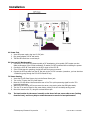
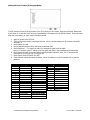
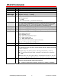
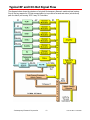
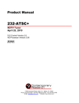
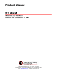
Product Manual
ICC1-IR
IR TV Controller, 1-way RF Coax Control
Ver. 2.0 October 31, 2002
17630 Davenport Rd, Suite113
Dallas, TX 75252 USA
Tel:
972.931.2728
888.972.2728
Fax: 972.931-2765
Web: www.crwww.com
www.contemporaryresearch.com
Table of Contents
Overview............................................................................................................................................. 3
Specifications...................................................................................................................................... 4
Physical .................................................................................................................................................4
Rear Panel .............................................................................................................................................4
iCC-Net..................................................................................................................................................4
CC-HSD Scan Sensor ..............................................................................................................................4
Includes ................................................................................................................................................4
Installation ......................................................................................................................................... 5
AC Power Test .......................................................................................................................................5
RF Coax and iCC-Net Operation ...............................................................................................................5
TV Power Sensing ..................................................................................................................................5
Setting IR Control Codes (IR Program Mode) ............................................................................................6
Setting Device Number and Parameters (Device Mode)..............................................................................7
IR Control Wiring ...................................................................................................................................7
RS-232 Control Protocol ..................................................................................................................... 8
Overview ...............................................................................................................................................8
Command String Structure ......................................................................................................................8
RS-232 Commands ............................................................................................................................. 9
iC-Net Zones ..................................................................................................................................... 10
System Map ...................................................................................................................................... 11
Typical RF and ICC-Net Signal Flow ................................................................................................. 12
Safety Instructions ........................................................................................................................... 13
Limited Warranty and Disclaimer ..................................................................................................... 14
Contemporary Research Corporation
2
ICC1-IR IR TV Controller
Overview
The ICC1-IR IR TV Controller delivers economical 1-way control for TV power, volume, and channels,
receiving iCC-Net network commands over the same broadband coax that carries the CATV channels.
Compact in size and price, the ICC1-IR features sensed power on/off control and intelligent tuning
from a channel list stored in onboard non-volatile memory.
•
•
•
•
•
•
•
Controls most brands of IR-controlled TVs
o Manages channel access by changing the TV’s internal available channel list
o Delivers absolute power control with included CC-HSD scan frequency sensor
Networks with up to 4,000 TVs through the ICC-HE Head-End Network Controller (HE)
o Receives 1-way individual and zone commands from a single RS-232 port on the HE
o Operates over same RF coax cable as CATV channels
o Low-loss internal RF tap saves amplification and installation costs
Provides LED feedback for network, IR control, and power status
Restores all power and channel status after loss of power from data stored in non-volatile
memory
Mounts on the back of the TV for simplified control and RF installation
Operates with Contemporary Research ABC Media System and iC Commander software, as
well as from RS-232 protocol from a custom-programmed PC or control system
Includes CC-HSD Scan Sensor, CC-IRE IR Emitter, RF loop cable, mounting Velcro, and 12VDC
power supply (U.S. only)
Contemporary Research Corporation
3
ICC1-IR IR TV Controller
Specifications
Physical
Size:
Weight:
Enclosure:
Mounting:
Rear Panel
RF In
RF Out:
Net LED:
IR Out:
5.5" [140mm] wide x 1.1" [28mm] height x 3.4" [86mm] deep
8 oz [226g]
All aluminum with durable black powder coat paint
Mounts rear of TV
IR Out LED:
‘F’, female, 75 ohm impedance, RF from CATV system, iCC-Net control
‘F’, female, 75 ohm impedance, RF to TV, less than -1.5 dbmV loss
Green LED for iC-Net bus and DC power, flashes once per second if active
3.5mm jack for CC-IRE IR Emitter cable or compatible CC-IRS serial cable
Supports carrier frequencies up to 62 KHz
Shipped with CC-IRE cable, 10 foot with stick-on IR emitter
Red LED lights when sending IR commands
Power Sensor:
Power Sensor LED:
3.5mm jack for included CC-HSD scan sensor or 5V logic-level input
Red LED lights when sensor indicates power on
Power In:
2.1mm coaxial jack (inside center conductor positive), 75 Ma maximum
11.5 to 16.5 VDC, 12 VDC typical (may be unregulated)
North American version includes UL/CSA listed wall power supply
S1 and S2, located on bottom of unit, sets IR code operation and device number
DIP Switches:
iCC-Net
Operation:
Data Receive:
1-way control, carried over the same RF coax connection as TV channels
Mid-band VHF, 74.7MHz, sent from ICC-HE
-25 to +35 dBmV signal level
CC-HSD Scan Sensor
Range:
Senses presence of TV scanning, from 15-35 KHz, magnetic pick-up
Includes:
3.5mm plug, 4ft. cable, stick-on TV sensor
Includes
CC-HSD Scan Sensor
CC-IRE IR Emitter
RF Loop cable, 18”
12 VDC power supply, 100 mA, (domestic US shipments only)
Mounting Velcro for unit and CC-HSD
Contemporary Research Corporation
4
ICC1-IR IR TV Controller
Installation
AC Power Test
1. Insert DC power supply plug into 12 VDC jack..
2. Plug power adaptor into AC wall outlet.
3. The Net LED should turn on and stay lit.
RF Coax and iCC-Net Operation
1. Connect the TV to CATV and observe quality of RF broadcasting. A low-quality CATV system can also
affect performance of the iCC-Net commands. If needed, fix CATV problems before installing the system.
2. Connect the CATV RF Coax cable into the RF In input on the iCC1-IR.
3. If the iCC-Net signal is operating, the Net LED will blink once per second.
4. Connect the RF loop cable from the RF Out jack to the TV’s RF connector (remember, you lose less than
1.5 dbmV by going through the ICC1-IR’S internal RF tap).
TV Power Sensing
1. Insert the CC-HSD Scan Sensor plug into the Power Sensor jack.
2. Turn on the TV using the TV’s power button.
3. Move the CC-HSD sensor block around the rear of the TV to pick up scanning signal from the TV’s
horizontal transformer
4. Watch the Power Sensor LED as you move the sensor, stop moving when the LED lights steady.
5. Turn the TV on and off from its own power button, testing if the unit is reliably sensing power.
6. Mount the sensor to the TV, using the enclosed Velcro tape.
Tip:
The best location for the sensor is usually on the lower left rear corner side corner (looking
from the front), and it may help to rotate the sensor to search for best performance.
Contemporary Research Corporation
5
ICC1-IR IR TV Controller
Setting IR Control Codes (IR Program Mode)
The DIP switches S1 and S1 at the bottom of the ICC1-IR serve in two modes, Program and Device, determined
by S2 Switch 6. In this step, you’ll set up the manufacturer’s IR codes sent from the IR Out port. These may have
been set at the factory, or you’ll need to set them yourself.
1. Apply DC power to the ICC1-IR.
2. If the unit’s device number has already been set, note the current settings for S1 switches 1-8 and S2
switches 1-4.
3. Set S2 Switch 6 to ON.
4. Look at the Manufacturer IR list and select the desired value.
5. Set S1 Switches 1 – 7 to match the value. For example to select the RCA codes,
turn on S1 switches 1 and 7, adding up to 8 to match the value in the Manufacturer IR chart below.
6. Set S1 Switch 8 to OFF for toggling Power On/Off command typical for most TVs. (There are a few
international TVs that use Key 1 for Power On)
7. Set S1 Switch 8 and S2 Switch 6 to OFF.
8. If unit’s device number had been set before, return S1 switches 1-8 and S2 switches 1-4 to previous
positions.
S1
1
2
3
4
5
6
7
8
S2
1
2
3
4
5
6
7
8
Off Value
0
0
0
0
0
0
0
Toggle power
On Value
1
2
4
8
16
32
64
Key 1 = Power On
Device Mode
IR Program Mode
Contemporary Research Corporation
Value
1
2
3
4
5
6
7
8
9
10
11
14
15
6
Manufacturer IR
Zenith
Panasonic
Toshiba
Hitachi
Sony
Grundig
Magnavox/Philips
RCA
Sony 2
Panasonic 2
Mitsubishi
Panasonic3 (2.0)
Sharp (2.0)
ICC1-IR IR TV Controller
Setting Device Number and Parameters (Device Mode)
In the next step, you’ll need to set up the device number and operation parameters for the ICC1-IR. Notice that
the functions of the S1 and S2 switches change when you set the unit in Device mode.
1. Make sure S2 Switch 6 is OFF (unit in Device mode).
2. Set the Device number by turning on the switches that add up to the desired device number. For
example, for Device #513 (1st device in Zone 2), S1 Switch 1 (1) and S2 Switch 2 (256) ON.
3. IR Carrier: Set S2 Switch 5 to OFF to send carrier with IR commands (default), ON to turn off carrier.
4. Power Sense Level: Set S2 Switch 7 to ON for high sensitivity for power (default), set to OFF if you
need to lower sensitivity (usually 2 adjacent TVs – side-by-side or through a wall).
5. IR Out Level: Set S2 Switch 7 to ON for high signal level (default), set to OFF if you need to lower IR
signal level to TV.
S1
Off Value
On Value
1
0
1
2
0
2
3
0
4
4
0
8
5
0
16
6
0
32
7
0
64
8
0
128
S2
1
0
256
2
0
512
3
0
1024
4
0
2048
5
IR Carrier On
No Carrier
6
Device Mode
IR Program Mode
7
Power sense low Power sense high
8
IR Out low
IR Out high
*Values in gray cells are the default settings.
Device Number Setting
Tip: Before you begin setting device numbers, be sure to create a System Map (See the System
Map section in this manual), listing out all the device numbers you need, according to location
and iC-Net Zone (See the iC-Net Zone section in this manual). By using a logical order of
device numbers, you can really simplify installation. For example, the first unit in Zone 1 is 257
(256 + 1). For all the devices in Zone 1, just set S2 Switch 1 on for 256 for all units in that
zone, then use the S1 switches to designate 1st, 2nd, 3rd, etc. device in that zone.
Of course, never use the Zone’s Virtual Device number (256, 512, etc) as an actual device
number. Whenever you send command to the zone’s Virtual Device number, all units in that
zone will respond at the same time.
IR Control Wiring
1. Connect the CC-IRE IR Emitter plug into the IR Out jack.
2. Mount the emitter cube to the TV case where the TV receives IR commands.
3. Mount the ICC1-IR to the TV using included Velcro tape.
4. Connect DC power to unit.
Contemporary Research Corporation
7
ICC1-IR IR TV Controller
RS-232 Control Protocol
Overview
RS-232 control for up to 4000 TV Controllers is provided through an iC-series Head-End Network Controller. The
ICC-HE Head-End manages iC-Net communication over RF Coax to ICC1 (1-way) and ICC2 (2-Way) TV
Controllers as well as ICW TV Controllers over twisted-pair Cat3/5 wiring. The ICW-HE Head-End operates on
the twisted-pair network only.
Each TV Controller is assigned a unique device number from 1 to 4000 to which control commands are
addressed. The devices are organized into 16 zones of 255 devices. All the devices in each zone will respond to
a single “virtual device number” — one device number that represents all devices in each zone. There is also a
global device number, 4095, that will command all devices in the system. This feature dramatically speeds up
system operation and programming, because one command can affect an entire group of devices—or all. To
take advantages of this feature, review the section iC-Net Zones in this manual.
In ABC Media Retrieval Systems, we reserve the first group of devices, 1-255, for components operating on a
connected control system. Zones 1-16 are used for CR TV Controllers, Video Display Controllers and Tuners. As
it’s unlikely any system will use all 4000 devices, this may be a good device standard for your system as well.
The Remote RS-232 port on the Head-End Network Controller can communicate from 1200 to 38.4K baud. The
factory default setting is 19.2K baud, 8 data bits, No parity, and 1 stop bit.
Command String Structure
Characters in command strings are expressed in a combination of hex and ASCII characters. For clarity, the
following protocol examples use the following conventions:
•
•
•
•
•
•
•
Single-byte hex numbers are preceded by the ‘$’ symbol
ASCII characters or strings are enclosed in single quotes
Numbers not marked as hex or ASCII are a single decimal byte
Parameters shown in < > brackets are single byte
A series of multiple commands or parameters are set apart by [ ] brackets
Commas separate the bytes, but are not part of the protocol
Double quotes enclose the command string, but are not part of the protocol
Command format:
“$A5,<dh>,<dl>,<ncb>,<cmd1>,<parameter> [<cmdN>]"
$A5
<dh>
<dl>
<ncb>
<cmd1>
<parameter>
[<cmdN>]
Starts the command
The zone or high order byte of the device
The unit or low order byte of the device (0 for global zone)
The number of command bytes to follow
The first command byte
Command parameters (not used by all commands)
Multiple commands can be concatenated, with byte count added to <ncb>
Contemporary Research Corporation
8
ICC1-IR IR TV Controller
RS-232 Commands
Command
Power
Power Off
P0
Description
This series of commands uses the sensed power capability of the ICC1-IR.
“$A5,<dh>,<dl>,2,’P0’ ” (6 bytes)
Power On
P1
“$A5,<dh>,<dl>,2,’P1’ ” (6 bytes)
Power Toggle
PT
“$A5,<dh>,<dl>,2,’PT’ ” (6 bytes)
Volume
VL
“$A5,<dh>,<dl>,3,’VL’,<vol level>” (6 bytes)
Sets TV volume level
0 = Mute
1 – 63 = Minimum level (1) to maximum volume (63)
Ts & Qs
T-series channel commands select a channel and display the channel label on the
TV, while Q-series commands don’t show the on-screen text. As the ICC1-IR does
not provide on-screen text, T and Q have the same effect. We’ve included the Tseries commands here, but the unit will respond to Q commands as well.
Channel Up
TU
“$A5,<dh>,<dl>,2,’TU’ ” (6 bytes) – Tunes to next channel up in Tune Ring
Channel Dwn
TD
“$A5,<dh>,<dl>,2,’TD’ ” (6 bytes) – Tunes to next channel down in Tune Ring
Force Channel
TC
“$A5,<dh>,<dl>,3,’TC’, <channel>” (7 bytes) – Tunes to a specific channel
124 =
125 =
126 =
127 =
0=
255 =
RGB 2 input on TV
RGB input on TV
Select TV’s composite A/V input
Select S-Video Input
Blank video output to TV
Unblank TV video (restore to previous channel)
Select Channel
TT
Tip: Not all TVs have S-Video and RGB inputs.
“$A5,<dh>,<dl>,2,’TT’ ” (6 bytes) – Tunes channel if included in Tune Ring
Tune Ring
TR
“$A5,<dh>,<dl>,<ncb>,’TR’, [<chan 1>, <chan N>]” (variable bytes)
This command stores a Tune Ring, a series of preset channels accessed by channel
up/down commands.
Ex1: “$A5,<dh>,<dl>,6,’TR’, 5,4,8,11” sets ring to channels 5, 4, 8 and 11
Tip: The ring follows the stored order, channels do not have to be in ascending
order
Control Lock
LM
Ex2: “$A5,<dh>,<dl>,8,’TR’, $82,5,$87,11” sets channels 2-5 and 7-11. You can
specify a range using MSB bit for the first channel; the next byte is the last.
“$A5,<dh>,<dl>,3,'LM',<control>” (7 bytes)
Locks out front panel and IR remote control functions.
Bit 7 Selects IR remote control operation, except vol. (0=enabled, 1=disabled)
Contemporary Research Corporation
9
ICC1-IR IR TV Controller
iC-Net Zones
To simplify controlling groups of devices, iC-Net is divided into 16 zones of 255 devices. All the
devices within each zone can be controlled simultaneously by sending a command to a single “virtual
device number”.
For example, noting the zone chart below, if we send a Power On command to device #256, any TV
controller numbered between 257 and 511 will instantly turn on. If we send a Power Off command to
device #4095, all devices in the system will turn off.
This is an immensely powerful feature, because most systems can only address one device at time. So
if you need to turn off all 50 TV in a zone, you would need to send 50 commands. In addition to the
hassles of creating multiple commands, there would be a long delay between the first and last
command. One command, instant response is easier.
As we noted before, ABC Media Retrieval Systems reserve Zone 0 for devices used in the central
control system, 1 -15 for iC-Net devices. This structure may be useful for your application, or you
could use Zone 0 just like any other iC-Net zone.
Zone
0
1
2
3
4
5
6
7
8
9
10
11
12
13
14
15
All Zones
Tip:
First Device
1
257
512
769
1025
1281
1537
1793
2049
2305
2561
2817
3073
3329
3585
3841
Last Device
255
511
767
1023
1279
1535
1791
2047
2303
2559
2815
3071
3327
3583
3839
4000
Virtual Device
0
256
512
768
1024
1280
1536
1792
2048
2304
2560
2816
3072
3328
3584
3840
4095
You've probably figured out that you never want to assign a virtual device number to an
actual device in the system. If you assigned #1536 to a device, all the TV controllers in Zone
6 would respond every time you sent a command to that one device.
Contemporary Research Corporation
10
ICC1-IR IR TV Controller
System Map
One of the key tasks for iC-Net integrators is to create a logical System Map, assigning device
numbers to TV controllers so they fall into logical zones. The device mapping could be sorted by type
or location; whichever suits the application.
iC-Net Zone
1
2
3
4
Zone
W 1st Floor
W 2nd Floor
E 1st Floor
E 2nd Floor
Room
Device
S1
S2
W151
W152
W153
W154
257
258
259
260
1
2
1+2
3
1
1
1
1
513
514
515
516
1
2
1+2
3
2
2
2
2
769
770
771
772
1
2
1+2
3
1+2
1+2
1+2
1+2
1025
1024
1025
1026
1
2
1+2
3
3
3
3
3
1281
1282
1283
1
2
3
1+3
1+3
1+3
1537
1538
1
2
2+3
2+3
1793
1794
1795
1796
1
2
1+2
3
3+3
3+3
3+3
3+3
2049
2050
1
2
4
4
W251
W252
W253
W254
E151
E152
E153
E154
E251
E252
E253
E254
5
Coffee Areas
G100
G150
G151
6
Day Care
TV 1
TV 2
7
Hallways
W1
W2
E1
E2
8
Office
Admin
A/V Center
All Zones
All
Contemporary Research Corporation
256
512
768
1024
1280
1536
1792
2048
4095
11
ICC1-IR IR TV Controller
Typical RF and ICC-Net Signal Flow
The diagram below shows the structure of a typical Contemporary Research media retrieval system.
One of the key aspects for iCC-Net communication is to provide a forward and return (sub-channel)
path for data if you’re using ICC2 2-way TV Controllers.
Contemporary Research Corporation
12
ICC1-IR IR TV Controller
Safety Instructions
Read before operating equipment.
1. Cleaning - Unplug this product from the wall outlet before cleaning. Do not use liquid cleaners or aerosol
cleaners. Use a damp cloth for cleaning.
2. Power Sources - Use supplied or equivalent UL/CSA approved low voltage DC plug-in transformer.
3. Outdoor Antenna Grounding - If you connect an outside antenna or cable system to the product, be
sure the antenna or cable system is grounded so as to provide some protection against voltage surges
and built-up static charges. Section 810 of the National Electrical Code, ANSI/NFPA No. 70, provides
information with respect to proper grounding of the mast and supporting structure, grounding of the
lead-in wire to an antenna discharge unit, size of grounding conductors, location of antenna discharge
unit, connection to grounding electrodes, and requirements for the grounding electrode.
4. Lightning - Avoid installation or reconfiguration of wiring during lightning activity.
5. Power Lines - Do not locate an outside antenna system near overhead power lines or other electric light
or power circuits or where it can fall into such power lines or circuits. When installing an outside antenna
system, refrain from touching such power lines or circuits, as contact with them might be fatal.
6. Overloading - Do not overload wall outlets and extension cords as this can result in a risk of fire or
electric shock.
7. Object and Liquid Entry - Never push objects of any kind into this product through openings as they
may touch dangerous voltage points or short out parts, resulting in a fire or electric shock. Never spill
liquid of any kind on the product.
8. Servicing - Do not attempt to service this product yourself as opening or removing covers may expose
you to dangerous voltage or other hazards. Refer all servicing to qualified service personnel.
9. Damage Requiring Service - Unplug this product from the wall outlet and refer servicing to qualified
service personnel under the following conditions:
• When the power supply cord or plug is damaged.
• If liquid spills or objects fall into the product.
• If the product is exposed to rain or water.
• If the product does not operate normally by following the operating instructions. Adjust only those
controls that are covered by the operating instructions. An improper adjustment of other controls may
result in damage and will often require extensive work by a qualified technician to restore the product
to its normal operation.
• If the video product is dropped or the cabinet is damaged.
• When the video product exhibits a distinct change in performance, this indicates a need for service.
* Note to CATV system installer: This reminder is provided to call CATV system installer's attention to
Article 820-40 of the National Electrical Code (Section 54 of Canadian Electrical Code, Part I), that provides
guidelines for proper grounding and, in particular, specifies that the cable ground shall be connected to the
grounding system of the building as close to the point of cable entry as possible.
Contemporary Research Corporation
13
ICC1-IR IR TV Controller
Limited Warranty and Disclaimer
Contemporary Research Corporation (CR) warrants this product to be free from defects in
material and workmanship under normal use for a period of two years from the date of
purchase from CR. Should such a defect occur CR will repair or replace, at their option, the
defective product at no cost for parts or labor.
This warranty extends to product purchased directly from CR or an Authorized CR Dealer.
Consumers should inquire from selling dealer as to the nature and extent of the dealer's
warranty, if any.
All warranty claims must be shipped pre-paid to the factory. Call or fax to obtain a Return
Material Authorization (RMA) number.
CR is not liable for any damages caused by any of its products or for the failure of any
products to perform, including any lost profits, lost savings, incidental damages, or
consequential damages. CR is not responsible for any claim made by a third party or made
for you by a third party. This limitation of liability applies whether damages are sought, or a
claim is made, under this warranty or as a tort claim (including negligence and strict product
liability), a contract claim, or any other claim. This limitation of liability cannot be waived or
amended by any person. This limitation of liability will be effective even if CR or an
authorized representative of CR has been advised of the possibility of any such damages.
Some states do not allow a limitation of how long an implied warranty lasts. Some states do
not allow the limitation or exclusion of incidental or consequential damages for consumer
products. In such states, the limitation or exclusion of the Limited Warranty may not apply to
you. This Limited Warranty gives you specific legal rights. You may also have other rights
that may vary from state to state. You are advised to consult applicable state laws for a full
determination of your rights.
Except as expressly set forth in this Limited Warranty, CR makes no other warranties,
expressed or implied, including any implied warranties of merchantability or fitness for a
particular purpose. CR expressly disclaims all warranties not stated in this Limited Warranty.
Any implied warranties that may be imposed by law are limited to the terms of this Limited
Warranty.
Contemporary Research Corporation
14
ICC1-IR IR TV Controller