1
Mechanical Installation Overview
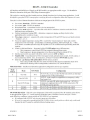
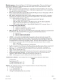
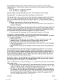
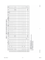
This NHP Series unit cannot produce airflow and cannot correct airflow problems inherent within the existing
furnace system. The following items should be carefully considered and properly followed for all installations:
Examination of the existing forced air furnace – Prior to starting this installation or furnace modification,
examine the total furnace system and make necessary comments or recommendations to the homeowner.
Remember, if a marginal condition exists within the existing forced air system, the installation of a geothermal
heat pump will not cure PRE-EXISTING conditions. Consider such items as proper fossil fuel ignition, is the
furnace cycling on hi-limit, filter, adequate cold air return, adequate supply duct and room register (1 register
per 100 CFM) etc.
Heating capacity – Size the geothermal heat pump according to the normal heating requirements as the
building exists today. Do not necessarily match to the existing furnace nameplate because it may be oversized.
Do not oversize the geothermal heat pump.
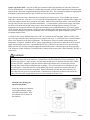
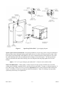
Supply plenum – Carefully examine all sides of the plenum. The coil must be installed on the supply side of
the fossil fuel furnace. Verify all transitions have angles less than 30°, the coil is centered within the plenum,
and there are no odd shaped angles or odd shaped transitions within the plenum.
Other plenum equipment – Auxiliary equipment such as humidifiers, zone plenum dampers, etc., located
within the plenum which may cause a non-uniform airflow issues may have to be removed if they cause to great
reduction to system airflow. Zone dampers within the trunk line at least 12" (30cm) from the coil typically are
no problem. When horizontal zone dampers are involved, perform all check-out functions with smallest zone
open first.
Comment – zone dampers cause back pressure on the blower and overall reduced airflow. Reduced
airflow can cause the geothermal unit to perform poorly or in some cases cause icing or freeze ups in
the geo loop or air coil.
Insufficient cold air return capacity – Installation experience indicates this is a major concern. In fact, it
could represent a problem in as many as 60% of the installations, especially if there is a requirement to increase
airflow with the existing blower and the existing cold air return capacity is already undersized or restricted.
Check the static pressure within the return cabinet or the suction at the filter cabinet door. Do not assume
because there is a register on the wall, the hole behind the register or the passageways are equal to this register.
Sharp offsets and transitions in the cold air return system often cause severe restrictions. Expect to add
additional registers or a relief register in the main cold air return duct.
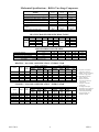
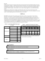
Blower CFM capacity – The furnace forced air system must have an airflow capacity larger than the minimum
requirement on the NHP Series specification sheet (see unit nameplate and/or Mechanical Specifications on
page 3). It is near impossible to correctly measure CFM airflow in an existing residential installation.
Experience and rule of thumb indicators will have to be followed to determine the existing furnace CFM
capacity. The following may be helpful:
a. Existing furnace nameplate - Typically represents a high or optimistic rating and is a function
of the systems static pressure. What changes have been made to the heating system since
installation?
b. Blower motor size - Used only as a minimal guide.
2 ton unit - 1/3 HP or larger
3 ton unit - 1/2 HP or larger
4 ton unit - 3/4 HP or larger
5 ton unit - 1 HP or larger
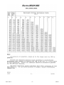
c. Observe/examine airflow ducting system and design - Use duct sizing table (ECØØ1), or
industry equivalent duct capacity airflow charts and determine if the system is capable of
09/11/2014
8
NI501