1
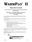
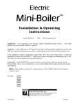
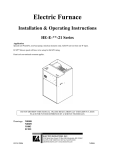
HeatChoice II ™ Electric Plenum Heater Installation & Operating Instructions (EH-***-*) Model Series · · · · · · Application Dual Heat – combine this electric plenum heater with stand-by gas or oil furnace. With or without standard air conditioning. Standard furnace blower or variable speed blower. Not compatible with heat pumps. Furnace fan center or wiring board equivalent required. Multi-zone compatible. HeatChoice II now has additional features and functions not available on the previous HeatChoice. The HeatChoice II has four LED indicator lights located on the door, whereas the original HeatChoice has only one. NOTE: This manual covers both upflow and downflow, study and follow the appropriate section. This model is also the best choice for total electric conversion or wood furnace (see appropriate section in this installation manual). U.S. and Canadian patents apply No. 4,593,176 and No. 1,177,512. Drawings: EH101 EA111 EC001 ES203 XX017 DO NOT DESTROY THIS MANUAL. PLEASE READ CAREFULLY AND KEEP IN A SAFE PLACE FOR FUTURE REFERENCE BY A SERVICE TECHNICIAN. 04/03/2009 EI204 Table of Contents Introduction 1 Specifications and Product Dimensions 2 Installation Requirements 3 Mechanical Installation Overview 4 Upflow 6 Downflow 8 Horizontal 8 Electrical Installation Overview Electrical Installation 10 Oil Furnace with “T and T” Control 12 Power On, Start Up 13 Operational Tips 13 Stat Override Timer (SOT) Additional Applications or Special Equipment Concerns Wood Furnace 14 16 16 Troubleshooting 18 Replacement Parts List 19 Drawings 04/03/2009 9 EH101 EA111 EC001 ES203 UAI012 XX017 EI204 Product Configurator EH-*** - * U = Upflow D = Downflow kW 10 = 10 kW 15 = 15 kW 20 = 20 kW 25 = 25 kW Width 8 = 18” 5 = 15” Introduction The Power of Choice is encouraging many homeowners to build versatility and flexibility into their heating system. When used and controlled properly, electric heat can save hundreds of dollars per year. To meet this Power of Choice need, this HeatChoice series plenum heater is very versatile with a variety of applications. This HeatChoice unit contains several patented mechanical, airflow, and electrical control features. The intent of these features is to reduce installation labor and add quality performance. Since these patented features cause this unit to be unique compared to other electric heating products, this installation manual must be studied and followed in detail. This is a pre-wired package for converting a new or existing oil, gas, or solid fuel furnace to a dual heat or total electric heating system. This is a complete package for standard air conditioning, utility load control, and optional DC drive variable speed furnace. There are no additional relays or option hardware needed for the outlined application. Also there will be no feedback to the air conditioning compressor unit with mechanical stat sub-base or digital room thermostats. The utility load control receiver properly switches the heating mode and properly controls the air conditioning unit during summer heat load interrupt. The blower circuit and control is also designed for heating interrupt (blower handled by gas furnace only) and continuous operating blower during cooling peak load interrupt. Typically these controls and design features are only found in this product or its US made equivalents. The kWh capacity should match the heat requirement of the house or building. Do not oversize your installation, sizing should be slightly smaller than the maximum requirement of the coldest day of the year. This unit can and is designed for continuous run operation on the coldest day of the year. Undersizing is possible, see a special section using SOT transfer timeout. Please read and understand conditions associated with proper installation, unauthorized changes, and POWER ON procedures. For information, all units are rated at 240VAC. When operating at lower source voltage, the output will be reduced. Example: 20 kW unit, assuming normal element tolerances 220VAC source - 16.8 kW, 76.4 amps 208VAC source - 15.1 kW, 72.3 amps Warranty Statement See the last page of this manual for detailed limited warranty coverage explanation. 04/03/2009 1 EI204 Specification Table Model Number: kW Rating Voltage/Phase Control Voltage Circuit Breaker Source Feed Elements Min. CFM Max. Temp. Rise Shipping Weight EH-*10-+ EH-*15-+ EH-*20-+ EH-*25-+ 10 240/1 24 volts 1-60 1 4 650 50° F 34# 15 240/1 24 volts 1-60, 1-30 2 6 900 50° F 36# 20 240/1 24 volts 2-60 2 8 1200 50° F 38# 25 240/1 24 volts 2-60, 1-30 3 10 1500 50° F 42# Loaded or electric call for heat operating voltage must be between 23 and 28 volts, 60Hz. This table primarily lists the various specification information at each kW size. The model number shown is the marketing or catalog number. The inside nameplate has the manufacturer’s model number (example – EH-U20-8 = EM-EU204C8). Product Dimensions 04/03/2009 2 EI204 Installation Requirements 1. All installation work must be performed by trained, qualified contractors or technicians. Electro Industries, Inc., sponsors installation and service schools to assist the installer. Visit our web site at electromn.com for upcoming service schools. WARNING ALL ELECTRICAL WIRING MUST BE IN ACCORDANCE WITH NATIONAL ELECTRIC CODE AND LOCAL ELECTRIC CODES, ORDINANCES, AND REGULATIONS. WARNING OBSERVE ELECTRIC POLARITY AND WIRING COLORS. FAILURE TO OBSERVE COULD CAUSE ELECTRIC SHOCK AND/OR DAMAGE TO THE EQUIPMENT. CAUTION This unit can only be used for its intended design as described in this manual. Any internal wiring changes, modifications to the circuit board, modifications or bypass of any controls, or installation practices not according to the details of this manual will void the product warranty, the CSA/us certification label, and manufacturer product liability. Electro Industries, Inc., cannot be held responsible for field modifications, incorrect installations, and conditions which may bypass or compromise the built-in safety features and controls. 2. If this is a Dual Heat system, this product relates only to the addition to the furnace ducting system external to the gas or oil force air furnace. The owner/ installer assumes all responsibility and/or liability associated with any needed installation of the gas/oil furnace, fuel system, flue, chimney, etc. Any instructions or comments made within this manual (or factory phone assistance) relating to the gas/oil furnace are provided as comments of assistance and “helps” only. CAUTION This unit shall not be operated (either heating section or blower) until the interior of the structure is completed and cleaned. This also means all duct work must be complete with filter, etc. Manufacturer’s warranty is void if this unit is operated during structure construction. CAUTION Hazards or unsafe practices could result in property damage, product damage, severe personal injury and/or death. 3. Remember, safety is the installer’s responsibility and the installer must know this product well enough to instruct the end user on its safe use. Safety is a matter of common sense - - a matter of thinking before acting. Professional installers have training and experienced practices for handling electrical, sheet metal, and material handling processes. Use them. 04/03/2009 3 EI204 Mechanical Installation Overview This HeatChoice unit cannot produce airflow and cannot correct airflow problems inherent within the existing furnace system. The following eight items should be carefully considered and properly followed for all installations: Examination of the existing forced air furnace – prior to starting this installation or furnace modification, examine the total furnace system and make necessary comments or recommendations to the homeowner. Remember, if a marginal condition exists within the existing forced air system, the installation of a HeatChoice will not cure PRE-EXISTING conditions. Consider such items as proper fossil fuel ignition, is the furnace cycling on hi-limit, filter, adequate cold air return, adequate supply duct and room register (1 register per 100 CFM) etc. Furnace type – Determine UPFLOW or DOWNFLOW furnace type. You must use the correct model for appropriate furnace type. The DOWNFLOW can be used in horizontal applications, follow instructions and install loose supplied sensor. Do not turn the HeatChoice upside down or install this unit in the cold air return. Heating capacity – size the HeatChoice according to the normal heating requirements as the building exists today. Do not necessarily match to the existing furnace nameplate because it may be oversized. Do not oversize the HeatChoice. Supply plenum – (this paragraph written primarily for UPFLOW; however, it also would apply to various DOWNFLOW or horizontal applications) - Carefully examine all sides of the plenum. Visualize an ideal location for the HeatChoice and follow all the details of the appropriate installation diagram. Verify all transitions have angles less than 30, the HeatChoice is centered within the plenum, and there are no odd shaped angles or odd shaped transitions within the plenum. One or more of the following will apply: a. No A-Coil – follow drawing (figure 1, page 6); ignore the sketched in “A-coil”. Notice all distribution ducts or pipes must be above HeatChoice elements with 1Ø" minimum clearance at top. If ample amounts of height is available, center unit between furnace top and lowest takeoff duct. b. Air Conditioning A-Coil – follow (figure 1, page 6). The HeatChoice must be above A-coil and parallel to A-coil. Again, all distribution ducts must be above the HeatChoice. c. Width, 16” Furnace – where possible use 15” model. If using 18” model, build out both sides or back with a 30 transition. Do not build out the HeatChoice mounting front. The build-out should be as high as possible so that the elements do not set in a pocket. NOTE: Do not use a 15" model in plenums larger than 18"x18". This is especially true when installing over an A-coil. The elements must be located at and close to the sides of the plenum. d. Width or DEPTH greater than 19" – only use the 18" model and follow drawing EH101 (C-1 and C-2). Ideally all plenums should be built-in so that the HeatChoice is inserted into 19"x19" box. The mounting plate or control box of the HeatChoice must be flat with the existing plenum. If plenum is too wide, build-in must be on both sides, equally. NOTE: Some plenums may require combinations such as a full vertical deflector, drawing EH1Ø1 (C-2) in the back and possibly an inverted "V" deflector, EH1Ø1 (C-1) on each side. e. Plenum access, hot objects – HeatChoice control box must be at least 12" from flue pipe or other hot objects. 04/03/2009 4 EI204 Other plenum equipment – auxiliary equipment such as humidifiers, zone plenum dampers, etc., located within the plenum which may cause a non-uniform airflow will have to be removed. Zone dampers within the trunk line at least 12" from the HeatChoice typically are no problem. When horizontal zone dampers are involved, perform all check-out functions with smallest zone open first. Comment – zone dampers cause back pressure on the blower and overall reduced airflow. The HeatChoice elements should be staged according to the heating load required by the various zone combinations. The Electro Industries’ WarmFlo series plenum heater is designed for zone systems and should be investigated for forced air zone applications. See page 17 section Reduced HeatChoice Output for details regarding this option. Air conditioning “W”, “M”, or “N” coils – these coils represent a double “A” or an “A” with a third slanted side. The net result is the top point no longer lines up with the center deflector of the HeatChoice frame. The known solution is adequate space between the coil top and the HeatChoice unit itself. A requirement of at least 10” is required between the top points of these new coils and the bottom of the HeatChoice frame itself. Reducing potential nuisance high limiting, can also be obtained by opening the XD jumper on the HeatChoice control board. See page 10 for details, in addition to keeping the minimum spacing of 10”. Insufficient cold air return capacity – Installation experience indicates this is a major concern. In fact, it could represent a problem in as many as 60% of the installations, especially if there is a requirement to increase airflow with the existing blower and the existing cold air return capacity is already undersized or restricted. Check the static pressure within the return cabinet or the suction at the filter cabinet door. Do not assume because there is a register on the wall, the hole behind the register or the passageways are equal to this register. Sharp offsets and transitions in the cold air return system often cause severe restrictions. Expect to add additional registers or a relief register in the main cold air return duct. Blower CFM capacity – the furnace forced air system must have an airflow capacity larger than the minimum requirement on a HeatChoice specification sheet (see Specification table on page 2) or the HeatChoice nameplate. It is near impossible to correctly measure CFM airflow in an existing residential installation. Experience and rule of thumb indicators will have to be followed to determine the existing furnace CFM capacity. The following may be helpful: a. Existing furnace nameplate - Typically represents a high or optimistic rating and is a function of the systems static pressure. What changes have been made to the heating system since installation? b. Blower motor size - Used only as a minimal guide. 10 kW unit - 1/4 HP or larger 15 kW unit - 1/3 HP or larger 20 kW unit - 1/2 HP or larger 25 kW unit - 3/4 HP or larger c. Observe/examine airflow ducting system and design - Use duct sizing table (ECØØ1), or industry equivalent duct capacity airflow charts and determine if the system is capable of delivering the CFM required on the nameplate. Especially check the number of registers and the number of “6 inch rounds”. The same would apply to cold air return duct capacity. d. Calculated CFM - By measuring the temperature rise across the existing furnace (or this electric unit), the CFM can be approximated. The accuracy of this formula will depend upon the estimated or determined Btu output (actual heat energy across the furnace). CFM = 04/03/2009 Btuh (output) Temperature Rise x 1.08 5 EI204 Mechanical Installation Upflow Using (figure 1) and visualizing the HeatChoice installation, work through the following eight steps: Step 1 Observe and select the insert location in the furnace plenum. a. Above A-coil b. HeatChoice II hole cutout at A-coil end (facing side) c. Depending upon the specific model, between 8” and 9.5” of space is required above the top of the A-coil. This space is where the HeatChoice II is physically inserted into the plenum. d. 10” minimum (in addition to the space required above) between control box and plenum top e. All distribution ducts above A-coil top Step 2 Measure plenum width and depth a. Step 1 determines facing side (hole cut decision) b. Width Figure 1 17” or less – 15” model 19” or less – 18” model 20” or greater – 18” model with baffling (see below) c. Depth 20” or less – no baffling 20” or greater – need rear baffling (see below) If your application falls in the 21” or greater mentioned above, field fabricate inside plenum baffling as shown in (figure 2). (Reference EH101 at the back of this guide for more illustrations). Figure 2 04/03/2009 6 EI204 Step 3 Cut insert hole using provided template, (figure 3). Figure 3 Step 4 Add necessary baffling. a. See Step 2 for determination and if required. The HeatChoice is designed with a special double plate at the element mounting. Cool air from the blower must blow between these two plates. Therefore, the Elector-Mate must be inserted into the base plenum such that the mounting plate is even with the edge of the hot air outlet hole. Do not necessarily line up the Electro-Mate control box with the furnace cabinet front. The concern is the hole in the bottom of the furnace mating with Electro-Mate elements. Step 5 Insert unit and bolt in place. a. Extend center V deflector to plenum depth. b. Do not drill into refrigerant lines. c. Note airflow decal. d. Seal as required. NOTE: When handling or inserting the actual HeatChoice unit, verify the element or the element fins do not become bent and the sensor probe is parallel with the top element. These probes must be approximately 1½” from element fin. Step 6 Be prepared to assist electrician with control wiring. a. If utility load control is not used or required, verify the blue and blue/ white wire remains shorted. Step 7 System checkout a. Responsibility of the contractor who “sold the job”. b. Warranty sheet suggests minimal steps. c. Complete warranty sheet and send to Electro Industries, Inc. 04/03/2009 7 EI204 Mechanical Installation Downflow For downflow installations, model numbers (EH-D**-*) must be used. Upflow models (EH-U**-*) cannot be used in this application. The basic mechanical installation instructions represented above in the upflow mechanical installation section apply to this section as well. Reference drawing EA111 located in the back of this guide for correct placement of the HeatChoice unit in downflow applications. Install the separately packed temperature sensor tube on the supply side of the HeatChoice. (Reference EA111 for correct placement). Mechanical Installation Horizontal For horizontal installations, model numbers (EH-D**-*) must be used. Upflow models (EH-U**-*) cannot be used in this application. Horizontal installations basically involve a downflow unit (EH-D**-*) turned 90° while the general installation rules common to the upflow unit apply. The key is to observe the “AIRFLOW” arrow and allowing for gravity temperature rise, making sure there is a probability for the hi-limits sensing at an upper point in case of airflow failure. Also, all airflow must pass uniformly through the elements. Feel free to call the factory for additional assistance with horizontal applications. Reference previous upflow installation steps, all requirements for plenum sizing and deflectors apply. This installation could represent a 15” model or an 18” model; again apply the rules outlined above. Air conditioning coil – typically we are aware of three physical coil types – flat (90° to horizontal duct), slant coil, and A-coil turned 90° (with an extended drip pan at the bottom). With these three types, the HeatChoice is typically installed after the coil or on the “supply” side. Again top and bottom and backside deflectors may be required depending upon plenum size. - Flat coil – allow at least 8 inches between coil and HeatChoice. - Slant coil – installing the HeatChoice at the same angle as the coil is preferred, or insert the HeatChoice as close as possible to the horizontal plenum bottom (assuming this is the furthest distance between coil and HeatChoice). - Turned A-coil – similar to an upflow, the HeatChoice must be inserted in line with the A-coil, with the HeatChoice deflector centered on the inverted “A” and as close as possible to the coil inverted A “top”. Insert the HeatChoice unit making sure the center deflector has its point toward the furnace. Verify that the unit is completely inserted so the air will flow between the element mounting plate and the front panel. Mount the unit to the plenum. Install the supplied temperature sensor tube supplied on the supply side of the HeatChoice. 04/03/2009 8 EI204 Electrical Installation Overview WARNING TO AVOID THE RISK OF ELECTRIC SHOCK OR DEATH, WIRING TO THE UNIT MUST BE PROPERLY GROUNDED. FAILURE TO PROPERLY GROUND THE UNIT CAN RESULT IN A HAZARD LEADING TO PERSONAL INJURY OR DEATH. Line Voltage The nameplate and/or Installation and Operating Manual specification page provides kW rating and operating current requirements for each specific model. Select the proper wire size to comply with your type of wire routing and NEC field wiring requirements. Field connection is at this product’s furnished circuit breaker. This integrated circuit breaker is a proper local disconnect. WARNING USE ONLY COPPER WIRE FOR CONNECTION TO THE CIRCUIT BREAKER TERMINALS AND INSIDE THIS PRODUCT’S CABINET. If the 240 power service is to be wired as single feed, order option circuit breaker single feed bus bar, part number 5701 (2 circuit breaker), 5702 (3 circuit breaker). WARNING DISCONNECT ALL ELECTRICAL POWER BEFORE ELECTRICALLY CONNECTING OR SERVICING THE UNIT. FAILURE TO DISCONNECT THE ELECTRICAL POWER BEFORE WORKING ON THIS PRODUCT CAN CREATE A HAZARD LEADING TO PERSONAL INJURY OR DEATH. Note: All heat/cool functions for this dual heat system originate from a standard 4-wire (heat/cool) room thermostat. Do not install with a 2-stage heat/1-stage cool or a heat pump room thermostat. Also do not install using two individual thermostats. Control Wiring – (reference figure 4) – this section assumes gas or oil furnace has an appropriate fan center or appropriate equivalent wiring terminals with 40VA or larger integral transformer and blower relay with “G” function. Use only a basic four wire heat/ cool type thermostat. Blower Control – this is handled within the 4 (or 5) wire connection between the HeatChoice control board bottom and the gas furnace hookup. The HeatChoice control board allows the blower to turn off and operate under the control of the gas furnace during standby or utility interrupt. During cooling the control board logic keeps the blower running during utility air conditioning interrupt to circulate summer air. a. Delay on/off – within the control board logic, the blower turns on with an approximately 10 second delay. At the end of the thermostat heat cycle, the blower will continue to operate for 60 seconds to cool off the HeatChoice metal rod electric elements. b. LMC Purge cycles – there is a 60 second delay before allowing a gas furnace W input in order to allow the furnace blower to cool off the HeatChoice elements. There is also a 3 minute delay before allowing the electric elements to turn back on after the gas furnace has been on. c. Thermostat “G” function – do not connect the thermostat G wire directly to the gas furnace G screw. The thermostat G wire must pass through the HeatChoice control module from top point to the bottom point. 04/03/2009 9 EI204 XD jumper – located on the mid right hand side of the HeatChoice control board is a jumper marked XD. When open, a 2-minute delay stage-up between each stage 2, stage 4, and stage 5 is added to the staging sequence. The intentions for this option is to bring the heat on slowly to reduce the possibilities of initial overheat and perhaps lessen high limit. The default factory setting for the XD jumper is closed. Downflow or Horizontal only – HI-LIMIT PROBE EM5714 (shipped loose in control box cabinet) – Install probe as close as possible below HeatChoice on the right side, see drawing EA111. Within the upper right portion of the main control box locate one of the two wire nuts that join a red wire from the right hi-limit probe to a red/white wire from the control board wire harness, (see figure 9). Remove wire nuts, route, and connect in series to this additional hi-limit probe’s red wires. Figure 4 Electrical Installation Step 1 240 VOLT SOURCE – route and wire from the appropriate service entrance panel directly to the HeatChoice circuit breakers, use only copper wire connected to breakers. The service entrance disconnect and 240 volt wire shall be sized according to the HeatChoice nameplate rating. The circuit breakers within this unit qualify as the appropriate local disconnect. Step 2 GROUNDING - Route and install the appropriate size conductor wire between the HeatChoice lug labeled "ground" and the building service entrance panel ground bus. Use NEC code requirements for grounding wire size. The conduit is not a sufficient ground conductor. 04/03/2009 10 EI204 Step 3 Room thermostat – use only basic 4-wire, heat/cool type. Route the standard R, W, G, Y roomstat screw functions to the HeatChoice DECII control board top tab/screw terminal adapters. Use wire to wire same letter connection. (figure 5) Figure 5 Step 4 Air conditioning, outdoor unit – this should be a 2-wire hookup, typically represents the contactor coil. Connect one wire to the top “YL” terminal and the second to a bottom “C” terminal. Note: off-peak load control for the air conditioner will not work if the wiring is not connected through the HeatChoice control board. (figure 6) Figure 6 Step 5 Gas (or oil with fan center) furnace – the furnace should have a 4 or 5-wire terminal block and match the control board bottom four terminals – R, W, G, C. (figure 7) - The furnace may also contain a “Y” screw, this is only needed if it is a variable speed (DC drive) furnace, see next section. - Depending upon furnace manufacturer, the common may have various letter terminology – C, B, X. “C” is 24-volt common for this product. Figure 7 Step 6 04/03/2009 11 EI204 Utility load control – extend the two blue wires to an appropriate set of wires or contact closure within the power company control receiver. For electric energy operation (offpeak) the two blue wires represent a contact closure as shipped. Do not apply external voltage or external power to the blue wires, they are simply looking for a closed contact during off-peak. (figure 8) - Optional – where load management interrupt does not apply simply leave the two blue wires tied together and wire nutted. - LMC reverse logic – Normal logic NC (normally closed) is simply the blue and blue/ white wires J3-2 and J3-3. NO (normally open) logic can be obtained by connecting the appropriate load control wires between the “X1” tab and “R” tab while the two blue wires remain wire nutted together. - In areas where “peak” control is accomplished by interrupting the 240 line voltage, other methods must be used to open the blue/blue white wires. Contact factory for more information. Figure 8 Downflow – Horizontal Sensor Probe (figure 9) Within the right portion of the main control box locate the two pigtailed red/ white wires with wire nuts on the ends. (See drawing ES203). Remove the wire nuts, route, and connect in series to this additional hi-limit probe’s red wires. Figure 9 Oil Furnace with “T and T” control (figure 10) information, isolation is required between fan center “W” and the voltage which will be experienced on oil control “T and T”. Normally the standard fan center simply passes the “W” voltage on to the gas valve. Warning: When installing or wiring an oil furnace, this isolated contact is extremely important. Unexplainable and strange control reactions have been experienced when this isolation relay is not installed. The isolation relay shown on the following drawing can be a basic 24-volt coil, single contact cube relay or you can order from Electro Industries – EE-5053 prepackaged relay. If you use EE-5053 it has wire leads, the connection for the wire colors are as follows: - 04/03/2009 Interface module, W – black/yellow Interface module, C – gray Oil control, T – yellow/green Oil control, T – blue/yellow Unused, cap off – orange/black Figure 10 12 EI204 Power On, Startup 1. Use the airflow verification procedure within the attached warranty certification form. If you experience hilimit cycling or plenum temperatures greater than specified, this must be corrected before leaving the site. Correction can include verification of proper placement within the plenum, plenum deflectors/baffles (previous diagrams), increasing overall furnace airflow capacity, enlarging furnace blower, or disconnecting lower elements to reduce the heating capacity. To disconnect elements, simply remove (starting with lower left element) the element wire going to the hi-limit. Tape off and protect both the element end and the removed wire. 2. Using general heating and utility load control experience, cycle the HeatChoice with the roomstat and load control receiver functions. - The blower must come on within 30 seconds and the blower will continue for 1 minute after termination of the heat cycle. The blower function from the HeatChoice will also terminate during load control. It is expected the gas furnace will do its own blower control during standby. 3. Check blower current, compare to nameplate reading and verify blower motor is not being overloaded. 4. Complete the warranty certification form and return to Electro Industries, Inc. address or fax shown. 5. Recheck all electrical connections and screws for tightness, including factory wiring. Operational Tips 1. Manual reset Hi-Limit – Located behind the hinged control board door is a 250°F manual reset. This breaks the circuit for all electric elements. However, connected in the same circuit loop is the automatic reset 170° F hi-limit. Normally the automatic reset should always take care of any overheat condition prior to tripping the manual reset. Therefore, you should not experience a manual reset condition unless there has been a true hardware failure. Two exceptions – a standby furnace (or wood furnace) having an outlet temperature greater than 250°F or cold startup without blower. Because of the sensitivity of this capillary manual reset, anytime there is a blower failure when the elements come on you can expect a manual reset. 2. Front panel stand-by/ electric switch – (figure 11) allows the user to condition the system to select an energy source. This can be used for repair or troubleshooting of the furnace or simply “Power of Choice” selection. CAUTION The front panel override switch should not be changed during a heat call. There are no purge cycles when manually changing the override switch with an active heat call and could cause an undesired overheat situation 3. Summer A/C – LMC control in the HeatChoice control board is fully independent of the front panel override switch. This means that the override switch can indeed be set in the stand-by mode during summer A/C control. 04/03/2009 13 EI204 4. DECII module indicators (figure 11) Front panel top red LED (Hi-limit) – illuminates when high limit switch is open. Front panel green LED (Control Power) – indicates 24-volt source from furnace and non-blown fuse. Front panel red/green LED (Heat Source) – indicates which heat source is being used, red = gas, green = electric, flashing red/green = utility load control. Front panel bottom red LED (Heat Call) – Indicates room thermostat call for heat. Red LED (inside bottom) – gas furnace W is receiving 24V. Figure 11 5. Front panel heat source LED – this is a multifunction LED the chart below shows the various conditions and functions of this LED. Heat Source LED Status Solid green Solid red Flashing red Flashing green Flashing red/ green Condition Normal operation, electric mode. Normal operation, Stand-by mode. SOT timeout in electric mode, heating in stand-by. SOT timeout in stand-by mode, heating in electric Utility load control heating in stand-by. 6. Stat Override Timer (SOT) – this is an internal timer which can be field set via the SOT jumper located on the upper right hand side of the control board. If this set run time (90 or 180 minutes) is exceeded before the thermostat is satisfied, the system automatically switches to either full electric elements or standby depending upon the position of the stand-by/ electric switch. This option will automatically switch to standby furnace if there is a system fault associated with inadvertent circuit breaker, manual reset hi-limit, etc. If the HeatChoice unit is undersized (intentionally or unknown) this option will automatically switch to standby heating if the HeatChoice electric unit cannot maintain temperature set point. Factory default is set at 90 minutes, to disable the SOT function, remove the jumper. Note: the control board must be powered down when making a change to the SOT jumper in order for the change to take affect. NOTE: Utility Load Control has priority, in on-peak control there is no SOT. 7. High limit return – Independent of the XD jumper, the closing of the high limit will always perform a 2 minute delay for stages 2, 4, and 5. 8. Secondary fan limit control – this sensor closes at 120°F on temperature rise. When closed, furnace G and Y (BL) tabs are activated. Note: when installed using a variable speed furnace the closing of this probe will only activate G or the continuous air function of the blower; it will force the blower to full speed. 9. Blower response – the blower has an approximate 10 second turn-on delay and will continue for 60 seconds after electric element power is turned off via the room thermostat. This is necessary to properly cool off the elements. Also note there is a 3 minute blower purge when switching from stand-by to electric. 04/03/2009 14 EI204 10. System temperature response – the overall temperature rise (both sides of HeatChoice) must be within the maximum specification, see "Specification Chart". If any portion of the plenum (above elements) is operating with an air temperature greater than 125°F, element life will be shortened. - CFM CALCULATIONS, THIS HEATCHOICE - By measuring the temperature rise across the HeatChoice, the actual CFM can be quite accurately determined. If you are having difficulty sustaining hi-limit operation, it may be a good idea to calculate the CFM according to this formula. To arrive at a stable output temperature, you can turn off CB #2 and operate only as stage one. This will allow you to verify or calculate the CFM without reaching hi-limit cycling. The accuracy of this formula will depend upon uniform and average temperature rise plenum thermometer readings and the accuracy of both the clamp-on amp meter and AC voltmeter. NOTE: The volts x amps x 3.4 value is the same as Btuh output. CFM = - Volts x Amps x 3.4 Temperature Rise x 1.08 CALCULATED CFM, OIL/GAS FURNACE - By measuring the temperature rise across the existing furnace, the CFM can be approximated. The accuracy of this formula will depend upon the estimated or determined Btuh output (actual heat energy across the furnace). You cannot use nameplate Btuh values. You must use a realistic estimated or measured true OUTPUT Btuh. CFM = Btuh (output) Temperature Rise x 1.08 11. Special stand-by furnace and special plenum width conditions – as we continue gathering installation experience, we are seeing several over temperature situations reoccurring. The intent of this paragraph is to provide additional help for four specific plenum conditions: a. Large burner pot oil furnace with the HeatChoice installed less than about 6" from the top of the heat exchanger/fire pot. - Install from either the back or front (inline with the flue or burner) b. HeatChoice installed from either side of an oil furnace. - Locate as high as possible above the oil furnace, but realizing elements need to be inline or below take off ducts c. Plenums width between 19" and 20½"" without the use of side deflectors. - Add deflectors per drawing EH101, C-1 d. HeatChoice installed above an A-coil where the HeatChoice sits directly on top of the A-coil without side deflectors. - Add deflectors per drawing EH101, C-1 04/03/2009 15 EI204 Additional Applications Furnace variable speed blower – (Figure 12) a fifth wire connection will be needed to speed up the gas furnace blower for air conditioning and HeatChoice electric heating operation. Add the fifth wire to the gas furnace “Y” terminal as shown on the diagram. Note: Connection wires shown are in addition to 4-wire thermostat and 4 wires to furnace. Note: In the latest version of the HeatChoice, external jumper wires are no longer needed to ramp up the blower for air conditioning and HeatChoice electic heating. Figure 12 AUX Load Control, other Electro products – on HeatChoice control board, bottom right, connect blues (from other product) to COM and EL. (Note: this is a true function from the blue wires, it does not follow the override switch). 2-stage or variable burner gas – most furnaces ignore or do not take W2 (or Ruud “V”) action unless there is an input to W1. This means you can take a wire directly from 2-stage heat roomstat W2 to the furnace W2 and until the system is switched over to standby with the HeatChoice control board activating W1 there should be no furnace action. 2-speed or 2-stage air conditioning – load control action may be required with the outdoor unit Y2. This can be accomplished by routing the roomstat Y2 through a relay contact (onboard tabs) and the outdoor unit Y2. - Roomstat Y2 – COM - EL – outdoor unit Y2 Wood furnace – inlet air sensor required, must order and install EM5713 sensor for all non-automatic standby applications. The heated air coming off of the wood furnace must be less than about 90° before the electric elements will activate. Install the EM5713 in series with the load management control blue wire (Figure 13). Figure 13 Large mass furnace heat exchanger, oil, etc. – if there was an active standby heat call during the release of a load control back to electric, the heat build-up within the heat exchanger and the heating up of electric elements may initially produce an output temperature which exceeds the manual reset (250°). Normal tubular gas furnace heat exchanger should not be a problem because the electric element initial temperature delay is approximately 3 minutes. By removing the XD jumper on the HeatChoice control board, a two minute delay is added between each stage 2, 4, and 5. This will help reduce the chances of experiencing nuisance tripping of the manual reset limit switch. 04/03/2009 16 EI204 Reduced HeatChoice output – (figure 14) the white/ blue jumper wire located on the upper right hand side of the control board (W1, W2) is designed to drop half of the HeatChoice heating elements when opened. When the jumper is opened stages 2, 4, and 5 are dropped, when applicable. Application: This option can be useful for multiple zones, load shed, outdoor thermostat, or any other external contact closure when needed to cut the output in half. Option: Purchase EB-5415A (hookup drawing EH020) for multiple zone applications, call factory for details. Figure 14 Total electric – in this case there probably is no utility load control receiver, simply keep the two blue wires shorted with wire nut and the furnace burner is probably disabled. Remove the SOT jumper located on upper right hand side of the HeatChoice control board. By removing the SOT jumper, this will prevent the control board from timing out during a heat call and attempting to turn on the standby heat source. The furnace is only used as a blower source. The 240 element power must come from the appropriate size CB breakers within the general service panel. Time-of-Use or Time-of-Day – installation is basically the same as the previous dual heat/load management concept, except the 240 power source probably comes from CB’s within the single general service panel. The control for the blue wires can be an internal contact within the TOU meter or a user provided time clock with its time function coincident with the TOU on/off-peak time. Note 1: When using an external time clock make sure the blue wires go to an isolated contact and make sure the time clock is not inadvertently providing line voltage to one of the blue wires. Line voltage will result in instant circuit board failure. Note 2: Some TOU or limited off-peak internal control contacts (Xcel, Wisconsin) have N.O. = offpeak logic. In this case connect to terminals X1 and R on the HeatChoice control board. Connecting to these two terminals provides for a reversed logic of the blue wires. Heat pump – this HeatChoice DECII control board has no provisions for heat pump operation or wiring. If there is a heat pump involved with this system, this is the wrong plenum heater product. Contact your local distributor for information on other models that include heat pump intelligent systems. Troubleshooting Fuse – the HeatChoice control board contains an integral 3A thermally resetting fuse. If tripped the control board will need to sit for a minimum of five minutes to allow the fuse to reset itself. Operational Conditions, Forcing Standby – these conditions are also monitored by the front panel Heat Source LED being red. 1. Utility Load Control 2. SOT timeout 3. Front energy selector switch Operational Conditions Which May Prevent Standby or Gas On 1. No call for heat – Heat Call LED is off 2. Heat Source LED green – utility is not controlling or front panel is not in override 3. Somehow stat terminal block Y is also energized or at 24 volts 4. Board K1 or K2 open/inoperative 5. Hang-up – power down, 10 seconds, power up 04/03/2009 17 EI204 Operational Conditions Which May Prevent Electric Mode Stages On 1. No call for heat – Heat Call LED is off 2. In Stand-By mode, see previous section 3. Hang-up – power down, 10 seconds, power up Conditions Which May Prevent Electric Elements On 1. Mechanical Hi-Limit, front panel top LED on 2. Board K1 or K2 open/inoperative 3. Inoperative element relays 4. HeatChoice circuit breakers off 5. Burnt 240 inside wires 6. Building power panel fusing or breakers open HeatChoice II Replacement Parts 04/03/2009 1 EMDEC5633 Control board 2 5127 Heating relay 3 EM5620 Heating element 4 5633 High limit 118°F 5 EM5729 LIMIT PROBE HL170/250 6" 6 EM5724 LIMIT PROBE BL 120°F 7 5652 Circuit breaker SD 60A 8 5650 Circuit breaker SD 30A 18 EI204 19” width or 20” depth PLENUM HEATER MODEL: EH-U25-8 W1 L2 L1 Y YL W2 BL 120 L2 DUAL HL7 R R 170°F BK BK HL RW Y BL 5DEL X1 J3 250°F 120°F II PC1 HL6 HL8 ENERGY CONTROL RW BK L1 G R L2 J1 L1 WHT/BLU STAT J1 W HEATCHOICE 4DEL COM CB1 CB2 CB3 BK 60A 60A 30A BK EL 2DEL SB J3 CB3 L2 CB2 L2 CB2 L1 CB1 L2 CB1 L1 1DEL LED3 BK C C W G R R BL BLW BK K8 R R BK BK K9 K10 YG R R BK R R BK E4 BK L2 BK HL4 BK E6 BK BK 118°F E8 BK BK CB3 K10 L2 CB1 VI K8 K9 118°F L2 K7 CB1 GY GY CB2 L2 BK GY R CB3 BK K6 BK YG E9 HL5 OBK BK K7 BK K6 R VI E7 BK GY R BK K5 HL2 BK L2 L2 118°F K4 R K5 BK WBL E2 BK CB2 BK OR WBL OBK VI YG L2 R CB2 BK K4 BK OBK E5 HL3 K3 N.C. CB2 L2 BK K3 GY E3 BK GY R BK WBL LMC K2 R CB1 L2 118°F OR BK GY BK GY BK GY R E1 HL1 K2 GY K1 K1 BK FAN CENTER CB1 L1 R OR COM 1WS J2 CB2 L1 YG VI OBK WBL OR R CB1 L2 R R BK BK BK 24 VAC R R BK BK E10 BK BK 118°F COMPONENT CODE WIRE CB CIRCUIT BREAKER BL BLUE R RED E 2500W BLW BLUE/WHITE RW RED/WHT K RELAY BR BROWN W WHITE PC CIRCUIT BOARD BRY BROWN/YELLOW WBL WHITE/BLUE OR ORANGE YG YELLOW/GREEN ELEMENT HL HI-LIMIT T TAB CODE BK BLACK TERMINAL SC SCREW COLOR TERMINAL GY GRAY OBK ORANGE/BLACK VI VIOLET Y YELLOW DECAL UAW720 rev.C DRAWING ES203 Rev.A P1 07-25-07 HEATCHOICE PLENUM HEATER MODEL: EH-(D,U)20-(5,8) WHT/BLU STAT W1 DETAIL L2 A EH-D**-* HL8 SEE ONLY HL6 R R RW R R 170°F BK RW BK 250°F CB2 60A 60A II PC1 BK HL RW X1 J3 250°F Y BL 5DEL 4DEL 120°F CB1 YL ENERGY CONTROL HL6 BK Y DUAL RW R 170°F HL5 HL7 BL 120 A HL7 R 170°F DETAIL EH-D**-* FOR W2 BK L1 G R L2 J1 L1 W J1 COM BK EL 2DEL BK SB J3 1DEL LED3 CB2 L1 CB1 L1 K7 K8 K7 K8 VI R R BK BK WIRE CB CIRCUIT BREAKER BL BLUE R RED E 2500W BLW BLUE/WHITE RW RED/WHT K RELAY BR BROWN W WHITE PC CIRCUIT BOARD BRY BROWN/YELLOW WBL WHITE/BLUE OR ORANGE YG YELLOW/GREEN HL HI-LIMIT T TAB TERMINAL SC SCREW TERMINAL R C C W G R BK R R CB1 CB1 L2 BK E4 BK BK E6 HL4 BK R BK 118°F BK BK 118°F L2 K6 COMPONENT CODE ELEMENT COLOR OBK BK CB2 BK K6 R VI E7 BK GY GY R BK K5 L2 R L2 118°F R K5 BK WBL K4 HL2 BK CB2 BK BK K4 BK OBK E5 HL3 K3 E2 BK L2 CB2 L2 BK K3 GY WBL N.C. CB2 E3 BK GY BK CB1 L2 BK GY BK LMC K2 R GY BK 118°F OR R GY E1 HL1 BK K2 GY K1 K1 OR WBL OBK VI R VI OBK WBL OR R R CB1 L2 R BK BK L1 OR J2 FAN CENTER CB1 L2 CB1 R BL L1 COM 1WS BK CB2 BLW 24 VAC CB2 L2 E8 BK BK CODE BK BLACK GY GRAY OBK ORANGE/BLACK VI VIOLET Y YELLOW DECAL UAW719 rev.C DRAWING ES203 P2 Rev.A 07-25-07 HEATCHOICE PLENUM HEATER EH-(D,U)15-(5,8) WHT/BLU STAT W1 L1 DETAIL L2 A EH-D**-* HL8 SEE DETAIL ONLY FOR HL6 R R RW R R BK RW BK 250°F CB2 60A 30A II PC1 BK HL RW X1 J3 250°F Y BL 5DEL 4DEL 120°F CB1 YL ENERGY CONTROL RW HL6 BK Y DUAL 170°F HL5 HL7 R 170°F W2 BL 120 A EH-D**-* HL7 R 170°F G R L2 J1 L1 W J1 BK MODEL: COM BK EL 2DEL BK SB J3 1DEL LED3 BK BK K5 K6 K5 K6 OBK R R BK BK WIRE BL BLUE R RED E 2500W BLW BLUE/WHITE RW RED/WHT K RELAY BR BROWN W WHITE PC CIRCUIT BOARD BRY BROWN/YELLOW WBL WHITE/BLUE OR ORANGE YG YELLOW/GREEN T TAB TERMINAL TERMINAL L2 C C W G R BK BK E6 BK HL4 BK 118°F CB CIRCUIT BREAKER SC SCREW E4 BK BK COMPONENT CODE HL HI-LIMIT R BL K4 118°F ELEMENT BLW BK WBL BK OBK CB1 OR WBL OBK K4 HL2 BK 118°F R BK L2 BK CB2 BK K3 E2 BK BK R E5 HL3 K3 GY L2 CB1 WBL N.C. CB1 BK E3 BK GY BK LMC R GY BK 118°F OR K2 R E1 HL1 K2 GY K1 K1 BK GY GY OBK WBL OR OR BK CB1 L1 R L1 R L2 CB1 FAN CENTER R CB1 J2 CB2 L1 L2 L1 L2 CB2 COM 1WS CB2 L2 R R CB1 L2 R BK BK 24 VAC CB2 COLOR CODE BK BLACK GY GRAY OBK ORANGE/BLACK VI VIOLET Y YELLOW DECAL UAW718 rev.C DRAWING ES203 P3 Rev.A 07-25-07 HEATCHOICE PLENUM HEATER MODEL: EH-E(D,U)10-(5,8) WHT/BLU STAT W1 HL8 SEE ONLY FOR HL6 R R RW R R 170°F R BK RW BK 250°F Y CONTROL II RW PC1 HL6 BK YL DUAL ENERGY 170°F HL5 HL7 BL 120 A EH-D**-* HL7 R 170°F DETAIL W2 BK A EH-D**-* G R DETAIL L2 J1 L1 W J1 BK HL RW X1 J3 250°F Y BL 5DEL 4DEL 120°F COM BK CB1 EL 2DEL BK 60A SB J3 1DEL LED3 C W C COM 1WS G R R BL BLW 24 VAC J2 L2 CB1 WBL E3 BK BK K4 K3 K4 WBL R R BK BK WIRE BL BLUE R RED E 2500W BLW BLUE/WHITE RW RED/WHT K RELAY BR BROWN W WHITE PC CIRCUIT BOARD BRY BROWN/YELLOW WBL WHITE/BLUE OR ORANGE YG YELLOW/GREEN T TAB TERMINAL SC SCREW TERMINAL L2 CB1 OR WBL K3 CB CIRCUIT BREAKER HL HI-LIMIT HL2 BK E2 BK COMPONENT CODE ELEMENT COLOR N.C. R BK 118°F LMC BK BK 118°F CB1 BK OR K2 GY BK K2 GY K1 R E1 HL1 GY GY WBL OR OR K1 BK L1 BK CB1 R L1 R L2 CB1 L2 CB1 R CB1 L2 R BK FAN CENTER E4 BK BK CODE BK BLACK GY GRAY OBK ORANGE/BLACK VI VIOLET Y YELLOW DECAL UAW717 rev.C DRAWING ES203 P4 Rev.A 07-25-07 Electro Industries, Inc. Limited Product Warranty Effective February 5, 2009 Electro Industries, Inc. warrants to the original owner, at the original installation site, for a period of two (2) years from date of installation, that the product and product parts manufactured by Electro Industries are free from manufacturing defects in materials and workmanship, when used under normal conditions and when such product has not been modified or changed in any manner after leaving the plant of Electro Industries. If any product or product parts manufactured by Electro Industries are found to have manufacturing defects in materials or workmanship, such will be repaired or replaced by Electro Industries. Electro Industries shall have the opportunity to directly, or through its authorized representative, examine and inspect the alleged defective product or product parts. Electro Industries may request that the materials be returned to Electro Industries at the owner’s expense for factory inspection. The determination as to whether product or product parts shall be repaired, or in the alternative replaced, shall be made by Electro Industries or its authorized representative. Electro Industries will cover reasonable labor costs to repair defective product or product parts for ninety (90) days after installation. TWENTY YEAR (20) LIMITED WARRANTY ON BOILER ELEMENTS AND VESSELS Electro Industries, Inc. warrants that the boiler elements and vessels of its products are free from defects in materials and workmanship through the twentieth year following date of installation. If any boiler elements or vessels are found to have a manufacturing defect in materials or workmanship, Electro Industries will replace them. TWENTY YEAR (20) LIMITED WARRANTY ON SPIN FIN ELEMENTS Electro Industries, Inc. warrants that the spin fin elements of its products are free from defects in materials and workmanship through the twentieth year following date of installation. If any spin fin elements are found to have a manufacturing defect in materials or workmanship, Electro Industries will replace them. FIVE YEAR (5) LIMITED WARRANTY ON OPEN WIRE ELEMENTS Electro Industries, Inc. warrants that the open wire elements of its products are free from defects in materials and workmanship through the fifth year following date of installation. If any open wire elements are found to have a manufacturing defect in materials or workmanship, Electro Industries will replace them. Page 1 of 2 XX017 THESE WARRANTIES DO NOT COVER: 1. Costs for labor for removal and reinstallation of an alleged defective product or product parts, transportation to Electro Industries, and any other materials necessary to perform the exchange, except as stated in this warranty. Replacement material will be invoiced to the distributor in the usual manner and will be subject to adjustment upon verification of defect. 2. Any product that has been damaged as a result of being improperly serviced or operated, including, but not limited to, the following: operated with insufficient water or airflow, allowed to freeze, subjected to flood conditions, subjected to improper voltages or power supplies, operated with airflow or water conditions and/or fuels or additives which cause unusual deposits or corrosion in or on the product, chemical or galvanic erosion, improper maintenance or subject to any other abuse or negligence. 3. Any product that has been damaged as a result of natural disasters, including, but not limited to, the following: lightning, fire, earthquake, hurricanes, tornadoes or floods. 4. Any product that has been damaged as a result of shipment or handling by the freight carrier. It is the receiver’s responsibility to claim and process freight damage with the carrier. 5. Any product that has been defaced, abused, or suffered unusual wear and tear as determined by Electro Industries or its authorized representative. 6. Workmanship of any installer of the product. This warranty does not assume any liability of any nature for unsatisfactory performance caused by improper installation. 7. Transportation charges for any replacement part or component, service calls, normal maintenance; replacement of fuses, filters, refrigerant, etc. CONDITIONS AND LIMITATIONS: 1. If at the time of a request for service the original owner cannot provide an original sales receipt or a warranty card registration then the warranty period for the product will have deemed to begin thirty (30) days after the date of manufacture and NOT the date of installation. 2. The product must have been sold and installed by a licensed electrical contractor, a licensed plumbing contractor, or a licensed heating contractor. 3. The application and installation of the product must be in compliance with Electro Industries’ specifications as stated in the installation and instruction manual, and all state and federal codes and statutes. If not, the warranty will be null and void. 4. The purchaser shall have maintained the product in accordance with the manual that accompanies the unit. Annually, a qualified and licensed contractor must inspect the product to assure it is in proper working condition. 5. All related heating components must be maintained in good operating condition. 6. All lines must be checked to confirm that all condensation drains properly from the unit. 7. Replacement of a product or product part under this limited warranty does not extend the warranty term or period. 8. Replacement product parts are warranted to be free from defects in material and workmanship for ninety (90) days from the date of installation. All exclusions, conditions, and limitations expressed in this warranty apply. 9. Before warranty claims will be honored, Electro Industries shall have the opportunity to directly, or through its authorized representative, examine and inspect the alleged defective product or product parts. Remedies under this warranty are limited to repairing or replacing alleged defective product or product parts. The decision whether to repair or, in the alternative replace, products or product parts shall be made by Electro Industries or its authorized representative. THESE WARRANTIES DO NOT EXTEND TO ANYONE EXCEPT THE ORIGINAL PURCHASER AT RETAIL AND ONLY WHEN THE PRODUCT IS IN THE ORIGINAL INSTALLATION SITE. THE REMEDIES SET FORTH HEREIN ARE EXCLUSIVE. ALL IMPLIED WARRANTIES, INCLUDING WARRANTIES OF MERCHANTABILITY AND FITNESS FOR A PARTICULAR PURPOSE, ARE HEREBY DISCLAIMED WITH RESPECT TO ALL PURCHASERS OR OWNERS. ELECTRO INDUSTRIES, INC. IS NOT BOUND BY PROMISES MADE BY OTHERS BEYOND THE TERMS OF THESE WARRANTIES. FAILURE TO RETURN THE WARRANTY CARD SHALL HAVE NO EFFECT ON THE DISCLAIMER OF THESE IMPLIED WARRANTIES. ALL EXPRESS WARRANTIES SHALL BE LIMITED TO THE DURATION OF THIS EXPRESS LIMITED WARRANTIES SET FORTH HEREIN AND EXCLUDE ANY LIABILITY FOR CONSEQUENTIAL OR INCIDENTAL DAMAGES RESULTING FROM THE BREACH THEREOF. SOME STATES DO NOT ALLOW THE EXCLUSION OR LIMITATION OF INCIDENTAL OR CONSEQUENTIAL DAMAGES, SO THE ABOVE LIMITATIONS OR EXCLUSIONS MAY NOT APPLY. PRODUCTS OR PARTS OF OTHER MANUFACTURERS ATTACHED ARE SPECIFICALLY EXCLUDED FROM THE WARRANTY. THIS WARRANTY GIVES YOU SPECIFIC LEGAL RIGHTS, AND YOU MAY HAVE OTHER RIGHTS WHICH VARY UNDER THE LAWS OF EACH STATE. IF ANY PROVISION OF THIS WARRANTY IS PROHIBITED OR INVALID UNDER APPLICABLE STATE LAW, THAT PROVISION SHALL BE INEFFECTIVE TO THE EXTENT OF THE PROHIBITION OR INVALIDITY WITHOUT INVALIDATING THE REMAINDER OF THE AFFECTED PROVISION OR THE OTHER PROVISIONS OF THIS WARRANTY. Page 2 of 2 XX017