1
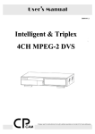
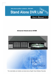
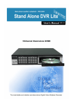
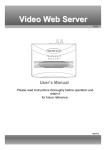
Real-Time Color Quad Processor
Model SLX912
Owner’s Manual
15540 Herriman Blvd. Noblesville, IN 46060 - Customer Support 1-800-774-0284
www.security-labs.com
Version: 1.0 DMS/MBR
CONTENTS
1. INTRODUCTION AND FEATURES ................................................................................................................................. 3
1.1 Product Introduction........................................................................................................................................................ 3
1.2 Product Features ............................................................................................................................................................. 3
2. INSTALLATION................................................................................................................................................................... 4
2.1 System Installation Diagram............................................................................................................................................ 4
2.2 Installation Procedures .................................................................................................................................................... 4
2.3 Illustration of installation procedures ............................................................................................................................... 5
3. OPERATING INSTRUCTIONS .......................................................................................................................................... 8
3.1 Introduction to the MASTER CONTROL panel............................................................................................................... 8
3.2 Operating instructions ..................................................................................................................................................... 9
3.2.0 ? Power On Reset and System Self-Test.................................................................................................................... 9
3.2.1 ? NORMAL DISPLAY MODE ................................................................................................................................ 9
3.2.2 ? SEQUENCE MODE............................................................................................................................................ 10
3.2.3 ? PLAYBACK MODE ........................................................................................................................................... 10
3.2.4 ? SYSTEM SETUP ................................................................................................................................................ 11
3.2.4.1 ? SYSTEM SETUP DESCRIPTION ................................................................................................................ 11
3.2.4.2 ? DATE/TIME SETUP .................................................................................................................................... 11
3.2.4.3 ? DISPLAY SETUP......................................................................................................................................... 13
3.2.4.4 ? TITLE SETUP .............................................................................................................................................. 14
3.2.4.5 ? MOTION SETUP.......................................................................................................................................... 15
3.2.4.6 ? PIP\POP SETUP ........................................................................................................................................... 17
3.2.4.7 ? LOAD DEFAULT & WATCH ALARM LIST .............................................................................................. 18
4. PRECAUTIONS .................................................................................................................................................................. 20
5. SPECIFICATIONS ............................................................................................................................................................. 21
2
1. INTRODUCTION AND FEATURES
1.1 Product Introduction
This surveillance unit can be installed in many different places such as: (homes, shops,
offices, etc.). It is designed with four objectives; to be Economical, Functional, Easily
Installed, and User Friendly?
1.2 Product Features
??An economic solution for home, shop or building surveillance system.
??Plug & Play - Installs easily and is suitable as DIY (Do It Yourself).
??Equipped with Microprocessor, compact dimension and smart functions. Simple
operation mode and user-friendly design.
??Full quad display at real time refresh rate.( NTSC: 60 Fields/sec; PAL: 50 Fields/sec)
??Automatic NTSC or PAL video system detection during Power On cycle.
??Built-in Buzzer for video loss, and motion event alarm.
??Built-in Real-Time-Clock( RTC) with On-Screen Display that shows date and time.
??User-friendly On-Screen Display( OSD) set-up menus and front panel design.
??Border line adjustment: nine colors and two border line widths.
??Supports motion detection for each channel in QUAD / FULL DISPLAY MODE.
??Each channel can display a title with up to 8 characters.
??Provides VCR-IN to support 2?2 Zoom-in and Freeze function for playback.
??Automatic video loss detection triggers alarm and shows a message on the monitor when
video input loss occurs.
??Built-in digital adjustments: brightness, contrast and hue for each channel.
??Built-in Color-Bar generator that enables easy monitor calibration.
??Supporting adjustment: nine OSD character colors.
??Supports: Quad / Full / PIP / POP /Auto-Sequential and Playback display modes.
??Sequential switcher allows random sequence and programmable dwell times.
??Automatically detects unconnected channel and skips that channel in auto-switch mode.
??Alarm triggered relay output( RELAY OUT) for a video recorder.
??40 alarm record list menu.
??Low power consumption.
2. INSTALLATION
3
2.1 System Installation Diagram
2.2 Installation Procedure
COM/NO/NC
MONITOR QUAD
OUT
OUT
POWER IN
VIDEO IN
RELAY OUT VIDEO OUT
VCR
IN
DC 12V
4
3
2
1
Back Panel
§Terminal Function Description.
Terminal
DC 12V
DC Power Input
DC POWER INPUT terminal: 12Vdc±10%.
Jack
COM/NO/NC
MONITOR
OUT
Function Description
Alarm Triggered Alarm output N.O. (Normally Open) or N.C. (Normally
Relay Output Closed) used to trigger a security video recorder.
Video signal
output BNC type Video signal output to monitor.
Terminal
Terminal
Function Description
4
QUAD
OUT
VCR
IN
Video signal
This is the video signal output for connecting to an external
output BNC type
VCR.
Terminal
External video
signal input BNC This is the video signal input for connecting to an external
type Terminal VCR.
from the VCR
CH1 video signal
This is the video signal input for connecting from an
input BNC type
external camera.
Terminal
1
CH2 video signal
This is the video signal input for connecting from an
input BNC type
external camera.
Terminal
2
CH3 video signal
This is the video signal input for connecting from an
input BNC type
external camera.
Terminal
3
CH4 video signal
This is the video signal input for connecting from an
input BNC type
external camera.
Terminal
4
2.3 Illustration of installation procedures:
Step 1: Figure below shows Illustrations of the external video Cameras, Monitor and VCR:
RELAY OUT
COM/NO/NC
VIDEO OUT
MONITOR QUAD
OUT
OUT
VIDEO IN
POWER IN
VCR
IN
DC 12V
Master
4
3
2
1
Camera 1
Monitor
Camera 2
VCR
Camera 3
Camera 4
Step 2: (Optional) To connect alarm output trigger to a video recorder
5
Item
Diagram
Setup Expatiation
Specifications of the Connector Wires:
SOLID WIRE
??Insulator stripped off length: 8.5 +0.5 /
-1.5? ?
??Maximum gauge: ? =2.3? ( 14~
24AWG) ?
2.3.3or
a
STRANDED
2.3.3-
R
C
E
O
L
AY
M
OU
O
/ N
/
Connect the external VCR system line
(External VCR Start Record) into the RELAY
OUT terminal.
T
N
C
From
b
VCR…ect.
or
( ? Please check your Time-Lapse VCR or
DVR user’s manual for configurations on
“RELAY OUT” terminal connections.
Please take note on COM-N.O. and
COM-N.C.)
To connect RELAY OUT terminal wires, please follow the instructions below:
T
OU
C
AY
N
/
EL
O
R
N
M/
O
C
¦
T
OU
C
Y
N
LA
/
E
O
R /N
M
O
C
¦
+
? . Insert a flathead screwdriver into the orange color release button (on the top of the
terminal connectors).
? . Push upward.
? . Insert terminal wires. (Disconnect wires in same fashion using release button)
6
Shown below is an illustration of CCTV/ VCR setup - "RELAY OUT".
OR
N IT
MO T
OUT OU
LAY C
RE / NO /N
CO
M
“External Start Record”
connector on the VCR
? Attention! The maximum voltage and current for the relay out is DC24V/2Amp.
Step 3: Plug one end of the power adaptor into the "DC IN" socket and the other end into the
AC power socket as shown below.
RI
WE
PODC12V
N
Adaptor
1
Power
Source
2
IN
ERV
W
PO C12
D
1
Adaptor
Plug the end of the
power adaptor into
the "DC IN" socket
2
7
3. OPERATING INSTRUCTIONS
3.1 Introduction to the MASTER CONTROL panel
1 2
3 4
QUAD
AUTO
¡ ö
¡ ÷
¡ Ï
1
2
3
¡ Ð
4
NEXT PAGE
PLAY MENU
?FREEZE
Front Panel? Operation Key Function Descriptions.
Mode
Light
Normal Mode
Key
QUAD LED
light
1 2
3 4
QUAD
?FREEZE
AUTO
¡ ö
1
¡ ÷
2
¡ Ï
3
Mode
Enter to QUAD
Display mode.
?FREEZE
AUTO Seq.
Mode
QUAD LED
flash
QUAD LED
light
AUTO LED
light
QUAD LED
light
Disengage
from image
freeze mode.
QUAD LED
light
Enter to AUTO
Sequential
mode.
(AUTO LED
dark)
Back to normal
QUAD display.
1 LED light or
dark
CH1 Full
display.
Freeze /
Release CH1
image.
2 LED light
2 LED light or
dark
CH2 Full
display.
Freeze /
Release CH2
image.
3 LED light
3 LED light or
dark
CH3 Full
display.
Freeze /
Release CH3
image.
Normal Mode
?FREEZE
PLAYBACK
FREEZE Mode
PLAY LED light
MENU Mode
MENU LED
light
QUAD LED light
(AUTO LED
Freeze / Release
dark)
Enter to Full
Full playback
Back to normal playback image.
image.
QUAD display.
AUTO LED
light
1 LED light
PLAYBACK
Mode
1 LED light
1 LED light
1 LED light
(AUTO LED
dark)
Enter to 2?2 Freeze / Release
Back to normal image display of 2?2 image of
quadrant 1.
quadrant 1.
CH1 Full
display.
2 LED light
2 LED light
Change to left
field. ?
2 LED light
(AUTO LED
Enter to 2?2 Freeze / Release
dark)
Change to right
Back to normal image display of 2?2 image of
field. ?
CH2 Full
quadrant 2.
quadrant 2.
display.
3 LED light
3 LED light
3 LED light
(AUTO LED
dark)
Enter to 2?2 Freeze / Release
Increase value.
Back to normal image display of 2?2 image of
+
CH3 Full
quadrant 3.
quadrant 3.
display.
AUTO Seq.
Mode
PLAYBACK
PLAYBACK
MENU Mode
8
Light
Key
¡ Ð
4
PLAY
NEXT PAGE
MENU
Mode
4 LED light
CH4 Full
display.
QUAD LED
flash
4 LED light or
dark
Freeze /
Release CH4
image.
Mode
AUTO LED
light
4 LED light
FREEZE Mode
PLAY LED light
4 LED light
MENU LED
light
4 LED light
(AUTO LED
dark)
Enter to 2?2 Freeze / Release
Decrease value.
Back to normal image display of 2?2 image of
CH4 Full
quadrant 4.
quadrant 4.
display.
PLAY LED
light
PLAY LED
light
PLAY LED dark
Enter to VCR
PLAYBACK
mode.
(AUTO LED
dark)
Enter to VCR
PLAYBACK
mode.
Disengage from VCR
PLAYBACK mode.
MENU LED
light
MENU LED
light
MENU LED
light
Enter to Menu
set-up mode.
(AUTO LED
dark)
Enter to Menu
set-up mode.
To Next Page or
Disengage from
Menu mode.
(MENU LED
dark)
3.2 OPERATING INSTRUCTIONS
3.2.0 Power On Reset and System Self-Test.
Each time during Power On (Plug In), the master controller starts up with the procedure of
warming-up and self-testing.
Normally video input detection format starts from CH1 to CH4. When CH1 is unconnected, video
input detection skips CH1 and starts from CH2 to CH4 and so forth.
??After POWER ON and when no cameras have been connected, the "NO VIDEO" message will be
shown on the monitor.
??After POWER ON and the cameras have been connected, any sudden disconnection will automatically
trigger the alarm, and the "LOSS" message will be shown on the monitor.
3.2.1 NORMAL DISPLAY MODE.
? FULL SCREEN DISPLAY: Displays the images from Channels 1~4 on the monitor by pressing the
function keys [1~4].
? QUAD SCREEN DISPLAY: Press? QUAD? , monitor will show images by quad from Channels 1~4.
? FREEZE mode: press? QUAD? key again when QUAD LED is turned on in Normal mode. Then the
QUAD LED will flash until the processor returns to Normal mode.
9
? FREEZE the Channel: Press key [1~4], the 1~4 LED will turn on and freeze the image. To unfreeze,
press? QUAD? key again or wait until the FREEZE HOLD TIME period you have set elapses.
? PIP / POP DISPLAY: Displays Channels 1~4 PIP or POP on the monitor by pressing the function keys
[1~4] to display images. Follow the PIP / POP display setup on page 14.
3.2.2 SEQUENCE MODE.
? Press the? AUTO? key to enter AUTO SEQUENCE mode. The processor automatically changes to the
image, interval time and channels previously setup.
??Under AUTO SEQUENCE MODE, when no sequence has been set, the "NO SEQUENCE SETTING"
message will be shown on the monitor.
??Under AUTO SEQUENCE MODE, when all dwell times are set to 0, the "NO SEQUENCE TIME
SETTING" message will be shown on the monitor.
??Under AUTO SEQUENCE MODE, when no sequence video input has been set, the "NO SEQUENCE
VIDEO INPUT" message will be shown on the monitor.
??Under AUTO SEQUENCE MODE, when more than one setting (e.g. no sequence and the dwell time is
set to 0) is made simultaneously, the "SEQUENCE SETTING ERROR" message will be shown on the
monitor.
? When any key is pressed in AUTO SEQUENCE MODE, the processor will automatically return to
NORMAL DISPLAY MODE.
3.2.3 PLAYBACK MODE.
? Press the ? PLAY? function key, it will then enter into VCR PLAYBACK MODE, and the "VCR PLAY"
message will be shown on the monitor. In the VCR PLAYBACK MODE, the VCR OUT will change
to mute (blue background) and the unit will detect for video loss on channels [1~4].
??When the VCR is disconnected prior to entering PLAYBACK MODE the alarm automatically goes
ON, the "NO VCR" message is shown on the monitor, and the beeper sounds.
??When the VCR is disconnected, after entering PLAYBACK MODE the alarm automatically goes ON,
the "VCR LOSS" message is shown on the monitor, and the beeper sounds.
? Press the? PLAY?function key again in PLAYBACK MODE, the processor will then return to NORMAL
DISPLAY MODE.
? Press [QUAD] function key under VCR full screen image display, the processor will then freeze the full
screen image of the VCR and the message “FREEZE” will be shown on the monitor. To unfreeze press
the? QUAD? function key again, or wait until the VCR freeze hold times out.
? Press key [ 1 ~ 4 ], processor will display1 ~ 4 quadrant 2 ?2 zoom image. To release zoom
display-press the? QUAD? key.
10
? Press key [1 ~ 4 ] again in 2 ?2 zoom image display, the processor will then freeze1 ~ 4 quadrant 2 ?
2 zoom image and the message “FREEZE” will be shown on the monitor. To unfreeze, press? QUAD?
function key, or press key [1 ~ 4 ] again.
3.2.4 SYSTEM SETUP.
3.2.4.1 SYSTEM SETUP DESCRIPTION.
??Press the? MENU? function key to enter the MENU page (shown by Figure 1).
??Press the« ? » and« ? » buttons to change the field left and right. Pressing them more than 1 second
allows the field to change quickly left or right.
??Buttons« + » or« - » are used for increasing or decreasing a value. Pressing them more than 1 second
allows the value to increase or decrease by more than one value.
??After the setting value has been finalized, press the« ? » and« ? » buttons to change the field left or
right or press the« NEXT PAGE» key to disengage and leave this setting page.
3.2.4.2 DATE / TIME SETUP
... DATE/TIMES SETUP ...
DATE FORMAT: YY.MM.DD
DATE: 2003.08.27
TIME: 12:35:50
LOCATION: BOTTOM
MONITOR OUT DATE\TIME: ON
VCR OUT DATE\TIME: ON
-- SEQUENTIAL SETTING —SEQUENCE:
A 1 2 3 4 . . .
Figure 1.
DWELL TIME:
3 3 3 3 3 0 0 0
? DATE FORMAT: There are three kinds of DATE formats for display:
??? YY/MM/DD ? MM/DD/YY ? DD/MM/YY ?
«+»
YY? MM? DD
«+»
«- »
MM? DD? YY « + »
«- »
DD? MM? YY
«- »
Figure 2. DATE format with rolling mapping.
? DATE range: Year data from 2000 to 2099, Month data from 01 to 12, Day data from 01 to 30.
? The default is 2003? 01? 01
? TIME format: HH: MM: SS for display, Hour data from 00 to 23, Minute data from 00 to 59, Second
data from 00 to 59.
? LOCATION: There are six positions for the DATE / TIME display. On the LEFT TOP, TOP,
RIGHT TOP, RIGHT BOTTOM, BOTTOM and LEFT BOTTOM. (The default is BOTTOM)
TOP 2003.11.06 10: 20: 36
LEFT TOP
2003.11.06
10: 20: 36
RIGHT TOP
2003.11.06
10: 20: 36
11
Figure 2. DATE / TIME display location
? When the MONITOR OUT DATE / TIME is set to “ON”, the DATE / TIME will be shown on the
MONITOR OUT display.
? When the VCR OUT DATE / TIME is set to “ON”, the DATE / TIME will be shown on the
QUAD OUT display.
? SEQUENCE: There are eight positions to select and setup the random switching sequence.
Where: Q? QUAD display; 1? CH1 Full display; 2? CH2 Full display; 3? CH3 Full display; 4
? CH4 Full display; ? Skip.
?NOTICE:
? In AUTO-SWITCH MODE channels that are disconnected or have video loss will automatically be
skipped.
? When no sequence is set in the AUTO SEQUENCE MODE, “NO SEQUENCE SETTING” will be
displayed on the monitor, which activates the buzzer alarm.
? DWELL TIME: Sets the interval time corresponding to each sequence position. (Time range: 0~9
seconds.)
?NOTICE:
? When all dwell times are set to 0 in the AUTO SEQUENCE MODE, “NO SEQUENCE TIME
SETTING” will be displayed on the monitor, which activates the buzzer alarm.
? When no sequence is set and all dwell times are set to 0 in the AUTO SEQUENCE MODE,
“SEQUENCE SETTING ERROR” will be displayed on the monitor, which activates the buzzer alarm.
3.2.4.3 DISPLAY SETUP.
CH1:
CH2:
BRIGHT 64 BRIGHT 64
CONTRAST 64 CONTRAST 64
HUE
80 HUE
80
12
Figure 3.
? BRIGHT: Adjusts image brightness per channel [1~4].
The brightness range: 0~99.
? CONTRAST: Adjusts image contrast per channel [1~4].
The contrasts range: 0~99.
? HUE: Adjusts image hue (color saturation) per channel [1~4].
The HUE range: 0~99.
3.2.4.4 TITLE SETUP.
....
CH1:
CH2:
CH3:
CH4:
TITLE SETUP ....
ON CAMERA01
ON CAMERA02
ON CAMERA03
ON CAMERA04
CHARACTER COLOR: WHITE
Figure 4.
? When the MONITOR OUT TITLE is set to “ON”, the title of the channel will be shown on the
quadrant and on the full screen display.
?
CH 1~4 TITLE: Set by user with a maximum of 8 characters.
? ? The 65 characters used in title settings are as follows:
? 0? 1? 2? 3? 4? 5? 6? 7? 8? 9? A? B? C? D? E? F? G? H? I? J? K? L? M
? N? O? P? Q? R? S? T? U? V? W? X? Y? Z? a? b? c? d? e? f? g? h? i? j? k
? l? m? n? o? p? q? r? s? t? u? v? w? x? y? z? : ? . ? ?
? CHARACTER COLOR: The On Screen Display character color is adjustable by the user.
? WHITE? YELLOW? CYAN? GREEN? MAGENTA? RED? BLUE? BLACK? GRAY?
13
3.2.4.5 MOTION SETUP.
MOTION SETUP
POWER ON MOTION AUTO OFF
SENS MD.NUM RE DET
CH1: 70
03
64 OFF AREA
CH2: 70
03
64 OFF AREA
CH3: 70
03
64 OFF AREA
CH4: 70
03
64 OFF AREA
BUZZER ALARM TIME: 3 SEC
RELAY OUT TIMER:
Figure 5. 8 SEC
FREEZE HOLD TIMER: 30 SEC
?
POWER ON MOTION AUTO OFF (ON): After power on auto, disable all motion (OFF setting)
or enable all motion (ON setting).
? SEN (Sensitivity): Control Threshold value. Range: 10 ~ 99, 99 has a higher sensitivity rate than 10.
? MD.NUM (Detected window No.) : Number of motion detection windows. Range: 04 ~ 45.
FOR EXAMPLE:
? When MD.NUM is set to "04" – to enable motion detection, 4 motion detection windows must exist.
? When MD.NUM is set to "15" – to enable motion detection, 15 motion detection windows must
exist.
? RE (Refresh time): Reference Image Change time, Motion velocity control. Range 01 ~ 99,
? DET: The motion detection from Cameras 1~4 is adjustable by disabling motion (OFF setting) or
enabling motion (ON setting).
? AREA: The motion detection window settings for each camera. Total of 192 (16 column?12 row)
motion windows can be set.
??Press the« ? » and« ? » buttons to move the red bar to AREA item.
??Press the? PLAY? function key to enter the AREA (motion detection windows) setup.
??Press the« ? »and« ? »buttons to change the cursor (pink window) left and right. Pressing them more
than 1 second allows the cursor to change quickly left and right.
14
??Press the« + » or« - » buttons to change the cursor up and down. Pressing them more than 1 second
allows the cursor to change quickly up and down.
??Button« AUTO» is used for enabling (green window) or disabling (clear window) a detection
window. .
??Button« QUAD» is used for enabling (green windows) or disabling (clear window) the rows of
detection windows (it is done per row).
??Button« PLAY» is used for enabling (green window) or disabling (clear window) all detection
windows.
??Button« MENU» is to leave AREA setup.
? BUZZER ALARM TIME: Sets the duration of the buzzer alarm. (Time range: 0~240 second.)
? If the BUZZER ALARM TIME is set to 0, this function is disabled.
? RELAY OUT TIMER: Sets the time period that the RELAY OUT activation will last. (Time
range: 8~120 seconds.)
?
VCR FREEZE HOLD TIME: The processor will automatically release a frozen image after the
time period that was set elapses. (Time range: 0~30 seconds.)
? If the VCR FREEZE HOLD TIME is set to 0, this function is disabled.
3.2.4.6 PIP / POP SETUP.
PIP.POP SETUP
TYPE SON POSITION SIZE
CH1:
CH2:
CH3:
CH4:
OFF
PIP 3 X:15 Y:7 A
PIP 1 X:14 Y:7 B
POP
Figure 6.
? PIP / POP SETUP: Set the PIP or POP for each channel on full screen display.
? OFF? PIP? POP?
? TYPE – Activates or deactivates the PIP and POP feature per channel.
15
? PIP – Places a small video image from a single channel within the Full Screen Display of the
listed channel. Allows user to view 2 channels at once.
? POP – Places a small video image from the remaining 3 channels within the Full Screen Display
of the listed channel. Allows user to view all channels at once.
? SON – The number of the channel being placed within the Full Screen Display of the listed channel.
? The options for the SON display of PIP on full screen are: CH1 (2,3,4), CH2 (1,3,4), CH3 (1,2,4),
CH4 (1,2,3)
? The SON display position setting range: X=0~15, Y=0~7.
3.2.4.7 LOAD DEFAULT & WATCH ALARM LIST.
WATCH ALARM LIST
LOAD FACTORY VALUE
LOAD FACTORY RESET
BORDER LINE COLOR: WHITE
BORDER LINE WIDTH: OFF
NTSC COLOR BAR: OFF
VIDEO SYSTEM CHANGE
NOW VIDEO SYSTEM: NTSC
Figure 7.
??Press the« ? »and« ? »buttons to move the red bar up and down. Pressing them more than 1 second
allows the cursor to move quickly up and down.
??Buttons« + »or« - »are used for increasing or decreasing a value. Pressing them more than 1 second
allows the value to increase or decrease by more than one value.
??After a value is set, press the« ? » and« ? » buttons one last time to finalize the set-up or to
disengage. To leave this set-up menu, press the« NEXT PAGE» key one last time.
? WATCH ALARM LIST: List of alarm event records.
1. Press the« ? » and« ? » buttons to move the red bar to the WATCH ALARM LIST.
2. Press the« + » or« - » buttons to enter the watch alarm list (This menu is read only).
16
P: 01
NO AT CH YY.MM.DD HH\MM\SS
........................
P: 01
NO AT CH YY.MM.DD HH\MM\SS
.........................
01 VL 2 2003.08.25 12:35:07
02 MD 3 2003.08.25 15:05:32
03 MD 1 2003.08.26 09:52:46
04 VL 4 2003.08.27 18:22:21
NO ALARM RECORD...
LAST ALARM LIST ERASER
AT:2003.08.27 12:37:10
Figure 8: Alarm event list
Figure 9: Alarm message after Load
Default & Clear Alarm List operation.
3. Press the« + » or« - » buttons to skip to the front or next page.
4. Press the« NEXT PAGE» button to exit the watch alarm list page.
? The alarm list format:
0~ 40: Number of alarm event recordings
P01~ P05: Alarm list page number.
CH: Active channel.
AT: Active Type. (MD: Motion Detect. VL: Video Loss.)
DATE: Alarm active date.
TIME: Alarm active time.
? LOAD FACTORY VALUE: All system settings will return to the initial factory default settings.
(When this operation has been completed, the symbol “.” will be displayed.)
? LOAD FACTORY RESET: All system settings will return to the initial factory default settings and
clear all alarm list records. (When this operation has been completed, the symbol “.” will be displayed
on LOAD FACTORY RESET)
? BORDER LINE WIDTH :
user.? OFF? 4\2? 8\4?
The
border
line
width
settings
are
adjustable
by
the
? BORDER LINE COLOR: The On Screen Display border line color is adjustable to:
? WHITE? GRAY? BLACK? BLUE? RED? MAGENTA? GREEN? CYAN? YELLOW?
? COLOR BAR: For calibrating the monitor.
If the video system (format) is NTSC, NTSC COLOR BAR: OFF is displayed, otherwise
PAL COLOR BAR: OFF is displayed.
? VIDEO SYSTEM CHANGE: Switch NTSC/PAL system.
17
4. PRECAUTIONS
1.
Keep away from moisture, fire, and vibration. Do not remove the cover to avoid the risk of electric
shock.
2.
Keep the temperature between -10? ~50? , relative humidity lower than 85%.
3.
Keep the unit well ventilated. Do not stack anything on the top of this processor.
4.
Please do not use any other power adapter but the one supplied with this unit. It is strictly prohibited to
insert any other plug into the DC IN socket, use only the specified DC12V±5% / 1.0A power adapter.
5.
The timer for the RELAY OUT & BUZZER ALARM has a duration error of plus or minus 1 second.
5. SPECIFICATIONS
(Note: Design and specifications are subject to change without prior notice.)
Video Input Ports
Picture Refresh Rate
Video Format
Video Input
Video Output
VCR IN
Quad Out
Monitor Out
Resolution( H×V)
Synchronous System
Zoom Function
Timer Generator
Title Generator
Auto Sequential Dwell
Time
Freeze Duration
Alarm Buzzer Timing
Alarm Relay Out
Power Supply
Power Consumption
Dimension: W×H×D
Operating Temp.
4 Cameras.
NTSC: 60 Fields / sec; PAL: 50 Fields / sec
NTSC or PAL Monochrome video signal.
4 BNC connectors. 75O Loaded.
2 BNC connectors.
1 BNC connectors. 75O Loaded.
QUAD Only video output 1 Vp.p. / 75O Load.
Full screen or Quad output 1 Vp.p. / 75O Load.
NTSC: 860×525 / PAL: 860×625 pixels. (CCIR-601 Standard)
Internal, Negative Synchronous.
2?2 Zoom.
Built-in Real Time Clock.
Up to 8 characters for each channel
Adjustable: 1~9 sec.( 3 sec. for first system initialization)
Adjustable: 0~30 sec.( 3 sec. for first system initialization)
Adjustable: 0~240 sec.( 3 sec. for first system initialization)
Normal Open / Normal Close Adjustable: 8~120 sec; 8 sec. For first system
initialization.
DC 12V±10% / 500mA @Normal operation (1.0A max. @ Power On Reset)
6.0 Watt.( Max.)
218? ( W) ×44? ( H) ×204? ( D)
- 10 ~ + 50? ( 14 ~ 122? )
18
Security Labs Limited Warranty
Security Labs, Inc. warrants that if a Security Labs product proves to be defective in material or workmanship
under normal usage, Security Labs will provide without charge to the consumer, parts and/or labor necessary to
remedy the defect for the period of ONE YEAR from the date of purchase. The warranty period commences on
the date that the product is purchased by the consumer. Any implied warranty is also limited to the duration
above.
THIS WARRANTY DOES NOT COVER THE FOLLOWING: FLUCTUATIONS IN THE POWER SOURCE OR
LIGHTNING-RELATED DAMAGE; ATTACHED OR UNATTACHED ACCESSORIES; COSMETIC PARTS
SUCH AS KNOBS AND ACCESS DOORS; CABINET DAMAGE, INCLUDING DAMAGE IN TRANSIT;
ACCIDENTAL DAMAGE; MISUSE; ABUSE; UNAUTHORIZED PARTS USAGE OR REPAIRS; RECEPTION
PROBLEMS DUE TO INADEQUATE SIGNAL; UNAUTHORIZED INTERNAL CONTROL OF ADJUSTMENTS;
INSTALLATION; ADJUSTMENT OF CONSUMER CONTROLS; OR ANY OTHER USE OF THE PRODUCT
OTHER THAN THAT SPECIFICALLY PRESCRIBED IN THE OWNER'S MANUAL. THIS WARRANTY
APPLIES TO PRODUCT SOLD AS NEW AND NOT REMANUFACTURED OR B STOCK PRODUCTS.
SECURITY LABS, INC. DOES NOT ASSUME LIABILITY FOR ANY VIOLATION OF PRIVACY FROM ILLEGAL
RECORDINGS MADE ON THIS UNIT. THE USER/OWNER ASSUMES FULL LIABILITY FOR ANY AND ALL
RECORDINGS MADE FROM THIS UNIT IN A SECURITY OR SURVEILLANCE OPERATION OR IN ANY
OTHER USE. SECURITY LABS IS NOT RESPONSIBLE FOR RECORDINGS THAT VIOLATE LAWS OR
THAT MAY PROVE OFFENSIVE OR TEND TO INCRIMINATE ANOTHER INDIVIDUAL. LOCAL, STATE AND
FEDERAL LAWS MUST BE OBSERVED REGARDING ALL RECORDINGS.
To obtain warranty service, the consumer must provide the product along with evidence that will positively
identify the date that the product was purchased from Security Labs or an authorized Security Labs product
representative, dealer, retailer, or distributor. Prior to shipment, a RETURN AUTHORIZATION must be obtained
from SECURITY LABS; this will assist us in more efficient service on your unit, and possibly avoid shipment if
the adjustment can be made over the phone. If shipment is made, the cost for postage, insurance and shipping
of the product is the responsibility of the owner.
SECURITY LABS' OBLIGATION UNDER THIS WARRANTY SHALL BE TO REPLACE SUCH PARTS AND
PROVIDE LABOR AS STATED. SECURITY LABS WILL NOT BE LIABLE FOR ANY LOSSES OR
INCONVENIENCES DIRECT OR INDIRECT, OR CONSEQUENTIAL PROPERTY DAMAGES.
To obtain a warranty return authorization number, contact Security Labs’ Customer Service at:
SECURITY LABS, INC.
15540 HERRIMAN BLVD.
NOBLESVILLE, IN 46060
CUSTOMER SERVICE
1-800-774-0284
ONLINE: www.security-labs.com.
19