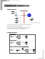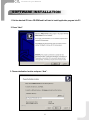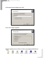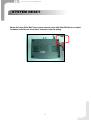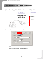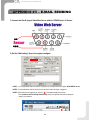
1
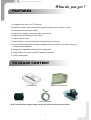
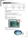
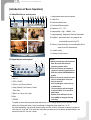
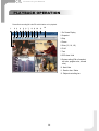
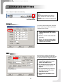
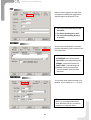
Evolution for your Demand
18
http://www.cpcamcctv.com
Video Web Server
User’s Manual
Please read instructions thoroughly before operation and
retain it
for future reference.
CPN101_V1.1
Evolution for your Demand
WARNING
The apparatus shall not be exposed to dripping. No objects filled with liquids, such as vases, shall be placed on the
apparatus.
The lightning flash with arrowhead symbol, within an equilateral triangle, is
intended to alert the user to the presence of uninsulated "dangerous voltage"
within the product's enclosure that may be of sufficient magnitude to constitute
a risk of electric shock to persons.
The exclamation point within an equilateral triangle is intended to alert the user
to the presence of important operating and maintenance-(servicing) instructions
in the literature accompanying the appliance.
TABLE OF CONTENTS
What do you get ?
FEATURES ----------------------------------------------------------------------------------------------------------- 1
PACKAGE CONTENTS ------------------------------------------------------------------------------------------- 1
SPECIFICATION ---------------------------------------------------------------------------------------------------- 2
Before Operation
IP ADDRESS APPLY ----------------------------------------------------------------------------------------------- 2
REAR PANEL -------------------------------------------------------------------------------------------------------- 3
HARDWARE CONNECTION ------------------------------------------------------------------------------------- 4
Software installation and System Reset
SOFTWARE INSTALLATION------------------------------------------------------------------------------------- 5
SYSTEM RESET------------------------------------------------------------------------------------------------------ 7
Static IP Setting
IP SETTING----------------------------------------------------------------------------------------------------------VIDEO WEB SERVER SETTING-------------------------------------------------------------------------------DVR REMOTE SETTING-----------------------------------------------------------------------------------------PIN CONFIGURATION--------------------------------------------------------------------------------------------CONNECT PC VIA INTERNET-----------------------------------------------------------------------------------
8
10
11
12
13
Dynamic IP Setting
DDNS APPLY--------------------------------------------------------------------------------------------------------LOGIN ROUTER----------------------------------------------------------------------------------------------------ROUTER SETTING------------------------------------------------------------------------------------------------IP SETTING----------------------------------------------------------------------------------------------------------Video Web Server SETTING------------------------------------------------------------------------------------DVR REMOTE SETTING-----------------------------------------------------------------------------------------PIN CONFIGURATION--------------------------------------------------------------------------------------------CONNECT ALL DEVICES----------------------------------------------------------------------------------------CONNECT PC VIA INTERNET-----------------------------------------------------------------------------------
Operation Guide
14
16
19
20
21
23
23
24
24
SOFTWARE OPERATION --------------------------------------------------------------------------------------- 26
PLAYBACK OPERATION ---------------------------------------------------------------------------------------- 28
ADVANCED SETTING -------------------------------------------------------------------------------------------- 29
APPENDIX#1 DVR CONTROL ----------------------------------------------------------------------------------- 33
APPENDIX#2 PTZ CONTROL ------------------------------------------------------------------------------------ 35
APPENDIX#3 EMAIL SENDING --------------------------------------------------------------------------------- 36
APPENDIX#4 SOFTWARE DOWNLOAD----------------------------------------------------------------------- 37
Evolution for your Demand
What do you get ?
FEATURES
1. Compatible with most of CCTV Products.
2. Empower all video output device watching and controlling on the Internet or LAN.
3. Auto Network Reconnection (ANR).
4. Support alarm triggers recording & watch dog function.
5. Support Dynamic IP address via a Router.
6. Support 4 alarm inputs.
7. Duplex function, record and playback simultaneously at client site.
8. Auto e-mail warning system & images uploading function (to FTP site) that will remind you
if external alarm happened.
9. Intelligent non-stoppable recording function after ANR.
10. Support Multi AP screens and HTTP display (IE browser).
11. Unique video player.
PACKAGE CONTENT
Video Web Server
Manual & Quick Start & CD
IP ADDRESS APPLY
Terminal block
Crossover LAN cable
NOTE : Please check the package to make sure that you receive all accessories shown above.
1
Adaptor
Evolution for your Demand
FEATURES
SPECIFICATION
Video Input
Alarm Input
Watch dog
RS-485 Port
Network Interface
Image Compression
Video Adjustment
Protocols
Hardware
2 Channels for analog & digital products, 1.0 Vp-p, 75, Composite, BNC
4 Inputs
Yes*
Yes
Ethernet (10/100 Base-T)
JPEG
Brightness, Contrast, Saturation, Quality Level adjust
TCP/IP, ICMP, SMTP, FTP, HTTP
CPU: 16 Bits RISC Processor, ROM: 512K Bytes Flash, RAM:8M Bytes SDRAM,
One RJ-45 for 10/100 Mbps Ethernet, LED to indicate Link / Act status,
GPIO w ith triggers for E-mail or FTP site
Resolution
Performance
Trigger & Action
VGA: 640x480, QVGA: 320x240
Installation
Security
Assign IP address
Power Source
Current consumption
DC 12V
Video through put : Up to 15(NTSC), 12.5(PAL) frames/ second,
Triggered by GPIO Input, Action: E-mail images or images uploading to FTP site's
specific accounts
Passw ord Protection
500 mA
Design and specifications are subject to change without notice.
*This function can keep Video Web Server to work normally and to avoid this unit to be down.
Before Operation
IP ADDRESS APPLY
Before installation, contact your ISP for your own IP address.
Note : The bundled software is compatible only with Windows operation systems : WIN2000, WIN2003
and WINXP. It is not suggested to use WIN98 & WIN ME which may cause system conflictions
with the software.
2
Evolution for your Demand
REAR PANEL
1. LAN
Connect Video Web Server to the Internet or LAN with cable or connect directly to PC with
standard pass through cable.
2. VIDEO INPUT (2 channels)
Connect to video source, such as camera or DVR video output.
3. ALARM I/O (optional for advanced applications)
Connect control devices, such as PTZ, DVR and external alarm signal input.
4. POWER
Plug in the supplied power adaptor (12V / 500mA).
5. RESET (at the bottom of Video Web Server)
Press this button to default setting (Refer to page 7).
5. REST
**LED light**
1)When it glitters, that means the system is normal.
2)When it lights, that means the network is normal.
1
2
3
Evolution for your Demand
HARDWARE CONNECTION
A . Connection Structure
NOTE:RS-485 for DVR controlling is optional.
1. Connect video output of camera or DVR with the video input of Video Web Server.
2. Connect PC with Video Web Server for IP setting.
3. Connect Video Server with ADSL or CABLE MODEM with Static IP address.
4. Connect PC with Internet and remote control Video Web Server.
B . Connection Application
4
Evolution for your Demand
SOFTWARE INSTALLATION
1. Put the attached CD into a CD-ROM and it will start to install application program into PC.
2. Press “Next”.
3. Choose destination location and press “Next”.
5
Evolution for your Demand
4. Set program shortcuts setting and press “Next”.
5. Press “Next” to begin copying files
6. After the installation, there are 6 files and 1 folder in your assigned path (file folder) as
below.
6
Evolution for your Demand
SYSTEM RESET
Before first using Video Web Server, please connect power with Video Web Server and push
the button under the unit more than 5 seconds to reset the setting.
REST
7
Evolution for your Demand
Static IP Setting
STEP 1: IP SETTING
1. Connect PC or Notebook with Video Web Server with crossover LAN cable.
Note : In some operation environments, users might need the standard CAT5 cable.
RJ-45
POWER
2. Network setting for PC. (The instruction is based on Win XP O/S. If your O/S is Win 2000 or
Win 2003, the setup procedure is similar to that on Win XP O/S.)
Click
3. Click on “Properties” for TCP/IP setup
8
twice
Evolution for your Demand
4. Click on “INTERNET PROTOCAL (TCP/IP)” and then select “Properties” to setup
5. Click on “Use the following IP address” and set IP address and subnet mask
NOTE :
1. Before changing the PC network setting, please write down the original network
setting in order to recover the original setting after the setup.
2. The IP address should be like 192.168.1.XXX. The setting of “XXX” could be set
from 1 to 254 besides 10(Because the IP 192.168.1.10 is the default IP ); the
subnet mask is 255.255.255.0.
9
Evolution for your Demand
STEP 2: VIDEO WEB SERVER SETTING
1. To configure the Server IP, please click
twice to enter the setup.
2. Key in User Name, Password, and Server IP (The default setting of User Name and
Password are admin; Server IP is 192.168.1.10, Port : 80). Then click OK to connect.
3. When you see the control bar it means that , you have successfully logged in the program
of the Video Web Server. Click on“System Config” to set up.
SYSTEM CONFIG
4. In the Peripheral setting, set baud rate, ID and model which you want to remote control later.
Press “APPLY” to enable the change after the setting.
10
Evolution for your Demand
5. Click on “System Config” again. In the Network setting, set server IP, gateway, net mask
and DNS which are provided from your local ISP ( internet service provider ). Press
“APPLY” to enable the change after the setting.
6. Disconnect PC and Video Web Server, and then link the static IP to the RJ-45 of video web
server.
Static IP
STEP 3: DVR REMOTE SETTING
1. Connect the DVR and monitor.
2. In the “Remote” setting, set the baud rate and ID that are the same as “Peripheral” setting
in the Video Web Server. And set remote mode to RS-485 (see example below).
A. 1 / 4 CH DVR
(MENU)
TIMER
CAMERA
RECORD
ALARM
DWELL
REMOTE
SYSTEM
EVENT
(REMOTE)
REMOTE MODE : RS-485
BAUD RATE : 2400
ID : 001
B. 4 / 9 / 16 CH DMR
(MENU)
SEARCH
TIMER
RECORD
CAMERA
SYSTEM
EVENT
(SYSTEM)
:
:
REMOTE MODE : RS-485
BAUD RATE : 2400
REMOTE ID : 001
11
Evolution for your Demand
STEP 4: PIN CONFIGURATION
After the remote setting, you have to connect DVR with the pins.
PIN 1, 6. RS485-A, RS485-B
Use RS485-A & RS485-B serial communication signals to control digital units just like that to
control DVR.
PIN 4, 7, 8, 9. ALARM INPUT
Use PIN 4,7,8,9 to receive the alarm input and then trigger Video Server to send mail to
users for auto e-mail warning system. (Alarm1, 2 are for CH1; alarm3, 4 are for CH2)
PIN 5. GND
Ground
PIN 2, 3. NORMAL HIGH, NORMAL LOW
Use PIN 2 or 3 to trigger external device to act.
Please see the example picture below for 1CH/4CH DVR.
RS485-A
RS485-B
12
Evolution for your Demand
STEP 5: CONNECT PC VIA INTERNET
1. Change PC network setting to the original setting and link PC to the internet.
2. Click
twice and enter your User name, Password (Note : If you never change the
“Account” before, the User Name and Password are both “admin”) and static IP which you
have set to Video Web Server in step 4.5. Then click OK to connect.
13
Evolution for your Demand
Dynamic IP Setting
STEP 1: DDNS APPLY
1. Click on free site “http://www.dyndns.org” ( please look at the example below, you can also
apply DDNS in other DDNS web page) and “ACCOUNT”
2. Press “Create Account”
3. Register the information and click on “Create Account”
14
Evolution for your Demand
4. After registering your account, you will receive an e-mail, which contains instructions to
activate your account. If you do not follow these directions within 48 hours, you will need to
re-register your account.
5. Login your account.
6. Click on“Account” and “Add Host”
7. Users can set up their own DDNS HOST. For example, the user’s applied Host name is
“test.dyndns.org”. And then press “Add Host” to finish the setting. (NOTE : Some
routers don’t support some DDNS HOSTs)
test
15
Evolution for your Demand
STEP 2: LOGIN ROUTER
NOTE : The following settings are different from router to router. Please read the instruction of
your router thoroughly.
1. Connect PC and router (LAN end)
POWER
2. Network setting for PC. (The instruction is based on Win XP O/S. If your O/S is Win 2000 or
Win 2003, the setup procedure is similar to that of Win XP O/S.)
Click
3. Click on “Properties” for TCP/IP setup
16
twice
Evolution for your Demand
4. Click on “INTERNET PROTOCAL (TCP/IP)” and then select “Properties” to setup
5. Choose “Obtain an IP address automatically”
6. Enter “Command Prompt”
17
Evolution for your Demand
7. In the setting window, enter “ ipconfig” to write down router’s gateway(e.q. 192.168.1.1)
8. Close the window above. Enter the IP address ( router’s gateway : 192.168.1.1 ) to
log in to the router from internet explore. And then enter the login web page and key in
the router’s user name and password.
18
Evolution for your Demand
STEP 3: ROUTER SETTING
NOTE : In the router setting, we have four steps as follows.
1. Dial setting
2. DHCP setting
3. Virtual server setting
4. DDNS setting
1. Press “INTERNER PORT” and choose your WAN type (e.q. PPPoE), and then enter your
“User Name” and “Password” of dialing up to dynamic IP. Press save after you set up.
test
2. Press “LOCAL PORT” and set “Start IP address” and “Number of IP address”. (For
example, if the IP address of Video Web Server is 192.168.1.10, then 10 is excluded from
the setting range) Press save after you finish setting up.
19
Evolution for your Demand
3. In “ADVANCED SETUP / Virtual Server”. Choose “By Port” and set “Port Number” to 80
for Video Web Server. And set “Local Server IP Address” to 192.168.1.10. (The default
Video Web Server IP and port). Press add after you set up.
4. In “ADVANCED SETUP / Dynamic DNS”. Key in the “DNS Account”, “User Name” and
“Password” that you applied in step 1. Press save after you set up.
test
test
STEP 4: IP SETTING
1. Connect PC or Notebook with Video Web Server with crossover LAN cable. Note : In some
operation environments, users might need the standard CAT5 cable.
RJ-45
POWER
20
Evolution for your Demand
2. Network setting for PC. (The instruction is based on Win XP O/S. If your O/S is Win 2000 or
Win 2003, the setup procedure is similar to that on Win XP O/S.)
Click
twice
Step 5 : VIDEO WEB SERVER SETTING
STEP 5: VIDEO WEB SERVER SETTING
1. To configure the Server IP, please click
twice to enter the setup.
2. Key in User Name, Password, and IP address (The default setting of User Name and
Password are both “admin”; IP address is 192.168.1.10, Port : 80). Then click OK to connect.
21
Evolution for your Demand
3. When you see the control bar, you have successfully logged in the program of the Video
Web Server. Click on “System Config” to set up.
SYSTEM CONFIG
4. In the Peripheral setting, set baud rate, ID and model which you want to remote control later.
Press “APPLY” to enable the change after the setting.
5. Click on “System Config” again. In the Network setting, set gateway as same as the
router’s gateway(192.168.1.1). Press “APPLY” to enable the change after the setting.
22
Evolution for your Demand
STEP 6: DVR REMOTE SETTING
1. Connect the DVR and monitor.
2. In the “Remote” setting, set the baud rate and ID same as “Peripheral” setting in the video
web server. And set remote mode to RS-485.(see example below)
A. 1 / 4 CH DVR
(MENU)
TIMER
CAMERA
RECORD
ALARM
DWELL
REMOTE
SYSTEM
EVENT
(REMOTE)
REMOTE MODE : RS-485
BAUD RATE : 2400
ID : 001
B. 4 / 9 / 16 CH DMR
(MENU)
SEARCH
TIMER
RECORD
CAMERA
SYSTEM
EVENT
(SYSTEM)
:
:
REMOTE MODE : RS-485
BAUD RATE : 2400
REMOTE ID : 001
STEP 7: PIN CONFIGURATION
After the remote setting, you have to connect DVR and the system with the pins.
PIN 1, 6. RS485-A, RS485-B
Use RS485-A & RS485-B serial communication signals to control digital units just like that to
control DVR.
PIN 4, 7, 8, 9. ALARM INPUT
Use PIN 4,7,8,9 to receive the alarm input and then trigger Video Server to send mail to
users for auto e-mail warning system. (Alarm1, 2 are for CH1; alarm3, 4 are for CH2)
PIN 5. GND
Ground
PIN 2, 3. NORMAL HIGH, NORMAL LOW
Use PIN 2 or 3 to trigger external device to act.
23
Evolution for your Demand
Please see the example picture below for 1CH/4CH DVR.
RS485-A
1CH/4CH DVR
RS485-B
STEP 8: CONNECT ALL DEVICES
ADSL modem
(WAN end)
DVR
STEP 9: CONNECT PC VIA INTERNET
1. Change PC network setting to the original setting and link PC to the internet.
2. Click
twice and enter your User name, Password and host which you have set to
Video Web Server. (Note : If you never change the “Account” before, the User Name and
Password are both “admin”). Then click OK to connect.
DDNS HOST
24
Evolution for your Demand
NOTE :
Static IP
1. In step 1.5 : Please make sure that your IP address should be 192.168.1.XXX. The setting of
“XXX” could be set from 1 to 254 besides 10 ( Because the IP 192.168.1.10 is
default IP )
2. In step 2.4 : Please make sure that the Peripheral setting should be as same as setting
of DVR which you want to remote later.
3. In step 5.2 : The Server IP is the IP you set in step 2.5.
Dynamic IP
1. In step 1.7 : Some routers don’t support some DDNS HOST.
2. In step 2.1 : Please use router’s LAN end to connect PC.
3. In step 2.8 : Please use IE browser to enter router’s gateway.
4. In step 3.1 : Please make sure that you have pressed save after you finish setting.
5. In step 3.2 : Please make sure that you have pressed save after you finish setting.
6. In step 3.3 : Please make sure that you have pressed add after you finish setting.
7. In step 3.4 : Please make sure that you have pressed save after you finish setting.
8. In step 5.4 : Please make sure that the Peripheral setting should be as same as setting
of DVR which you want to remote later.
9. In step 8 : Please use router’s LAN end to connect Video Web Server. Use WAN end
connect ADSL modem.
10. In step 9.2 : The Server IP is the DDNS HOST which you set in step 3.4.
25
Evolution for your Demand
SOFTWARE OPERATION
Follow the steps for connection at your client site (remote site). (e.g. If you set up the server at your
office with one static ADSL, you can remotely proceed to watch the video anywhere with a networked
computer.)
Step 1:Click
twice to enter Login setup (please refer to “software installation”)
Step 2:Key in “User Name” and “ Password”. Click “OK” to establish the connection.
NOTE:
1.There are two ways to get the software,
one is via attached CD, and the other
is via Video Web Server.(Refer to
APPENDIX#4)
Backup
Program
2.You can press “Address Book”
button to add a new IP into this
table or choose any logined IP
address to access the Video Server.
3.This function is designed to store
the list of IP addresses which you
can control and manage.
Play the last record file
Step 3:If you could see the video screen as following, you have been successfully connecting to
the server.
2004-DEC-23 [ THU ] 10:42:32 Aa 001.9 GB O/W
CAMERA01
CAMERA03
CAMERA02
CAMERA04
26
Evolution for your Demand
[Introduction of Basic Operation]
A. Video Web Server control panel
1
2
3
4 5 6 7 8 9 10 11
1. Image transmission rate per second
2. Video CHs
3. Data transmission rate
4. Connection/Disconnection
5. Resolution : D1、CIF
2004-DEC-23 [ THU ] 10:42:32 Aa 001.9 GB O/W
6. Image quality : High、Middle、Low
7. Image adjusting : Brightness/ Contrast/ Saturation
CAMERA01
8. Snapshot : press this button, the image will be
CAMERA02
automatically saved in the PC.
9. Record : press this button, the recording file will be
saved in the PC automatically.
CAMERA03
10. System config
CAMERA04
11. Number of online users
B. Digital device control panel
6
NOTE:
1.When you setup the video input from
DVR, the screen will show the
7
1
operation interface above.
2.Take 16 CH DVR as an example to
explain the operation (please refer to
DVR user manual & APPENDIX#1 for
details)
3.After you press the record icon, there
will be a recording file in the path
that you have set.
Each recording file can be save up
to 6000 frames.
The recording file will be assigned
to the second file if it is more than
6000 frames.
Besides, if the HDD space is less
than 200MB, the program will stop
recording.
2
3
4
5
1. CH1-4
2. PIP/+, QUAD/3. Zoom, Lock, Record, Search
4. Stop, Rewind, Fast Forward , Pause,
Slow, Play
5. Menu / up / down / left / right
6.Enter
7.TURBO*
To speed up menu selecting under video web server or PTZ shifting speed, you can activate "Turbo"
function by clicking this button. Users are allowed to change the turbo steps from 1 to 10.
For turbo step setting, you can enter system config, and click "toolbox" submenu to select the number of
turbo step. Ex. If you set "3" for turbo step, then when you press one of the button up/down/left/right, one
mouse click will as if you click 3 times.
27
Evolution for your Demand
PLAYBACK OPERATION
Please find a recording file in the PC and click twice on it to playback.
1
2 3
4
5
6 7
8 9 10
11
12
1. On Screen Display
2. Snapshot
3. Stop
4. Pause
5. Slow (1/2, 1/4, 1/8)
6. PLAY
7. Fast
8. OSD show / hide
9. System setting (Path of snapshot,
text color, progress color, channel
color)
10. Next Video
11. Duration time / Status
12. Playback controlling bar
28
Evolution for your Demand
ADVANCED SETTING
Click on “System Config” for advanced setting.
SYSTEM CONFIG
NOTE :
Apply-After all setting changes, press “apply” to
refresh the data in the Video Web Server.
Reboot-Press this button to restart Video Web Server.
Network
To set up the network setting of the Video Web
Servers, check with your network administrator
or Internet Service Provider.
1. You can get all the information, Server
IP, Gateway, Net Mask & DNS, from ISP
company.
2. Web Port : You can control Video Web
server via it.
3. IP Type : This unit only supports Static
IP address, if you want to use Dynamic
IP, please get it via a Router.
MAIL
When the alarm is triggered, the Video Web
Server will capture the instant picture and e-mail
the captured image to the assigned recipients.
1. You can get all the data from the ISP
company or by mailing to the server
supplier.(POP3/SMTP server)
2. You should set the mail list which you
want to send to when the alarm is
triggered.
3. If it is not necessary for you to verify
password and user’s name, please
choose Verify as “No”.
4. Please refer to appendix#3 for more
details.
29
Evolution for your Demand
FTP
When the alarm is triggered, the video server
will capture the instant picture and upload the
captured image to the assigned FTP site.
1. You can get all the data from your MIS
department.
2. The default uploading port is No.21.
3. You can set the uploading directory
by yourself.
ACCOUNT
Set up the user’s account( Max 10 accounts) ,
password and authority ( Max 5 accounts on line
at the same time) .
1.User’s level:
SUPERVISOR-control all the functions
HIGH LEVEL-control advanced functions
NORMAL -control basic functions only
GUEST LEVEL –watch the image only
2.Life time : During the period of time,
users are allowed to control the Video
Web Server.
PERIPHERAL
You can set up all the peripheral setting in this
Windows. (Refer to APPENDIX#1 & 2 for more details)
Peripheral Control : Set up video input
device. You can select the devices then
set up “Baud Rate & ID No.” to control the
equipments via Video Web Server.
30
Evolution for your Demand
File Path
You can modify the storing path for recording file
and snapshot images by yourself.
TOOLBOX
Upgrade the firmware and get the online users’
information.
NOTE :
Do not reboot the Video Web Server while
it is upgrading the firmware.
1. Firmware Version : The current
firmware version. You can click on the
“Find” button to get the latest firmware
from PC and press “Upgrade Firmware”
to upgrade it.
ALARM
Set up the ALARM function. You can use it
to operate “alarm trigger recording” function.
1. Alarm : Enable or disable Alarm trigger
function.
2. Method : Two selections—Email or FTP.
3. Resolution : Image storing resolution for
Email or FTP function.
4. Alarm Duration : Alarm duration time.
5. Post Image : You can select how many
images you need to store when alarm is
triggered.
6. Alarm record : Enable or disable “Alarm
trigger recording” function.
7. Alarm refresh : Clean the alarm
message “
” which is showed on the
screen.
31
Evolution for your Demand
Online User
1. The information of online user.
2. Chat function. Users are on line at the same
time and two of them can talk to each other.
Click the name of the other user. A window as
below will jump out. Click OK.
NOTE: Please turn (activate) all transmission
TCP and UDP ports. Fire wall and similar
software may disrupt normal transmission.
32
Evolution for your Demand
APPENDIX #1 – DVR CONTROL
1) Connect the Sub-D plug of Video Web Server with our own brand DVR products.
9
1
RS232-TX
GND
RS232-RX
RS485-B
VIDEO LOSS
RS485-A
SWITCH OUT
DISK FULL
ERROR OUT
ALARM RESET
REC START
ALARM INPUT
EXTERNAL ALARM NC
EXTERNAL ALARM COM
EXTERNAL ALARM NO
15
25
8
13
EXTERNAL ALARM NO
EXTERNAL ALARM COM
RS485-A
RS485-B
RS232-TX
RS232-RX
ALARM INPUT 9
ALARM INPUT 10
ALARM INPUT 11
ALARM INPUT 12
ALARM INPUT 13
ALARM INPUT 14
ALARM INPUT 15
ALARM INPUT 16
ALARM INPUT 1
ALARM INPUT 2
ALARM INPUT 3
ALARM INPUT 4
ALARM INPUT 5
ALARM INPUT 6
ALARM INPUT 7
ALARM INPUT 8
14
33
GND
1
Evolution for your Demand
2) Set the “Remote” function in the DVR products.
NOTE :
Remote mode : RS-485, Baud rate : selectable, ID : same as “Peripheral Control” in the Video Web Server.
A. 1 / 4 CH DVR
(MENU)
TIMER
CAMERA
RECORD
ALARM
DWELL
REMOTE
SYSTEM
EVENT
(REMOTE)
REMOTE MODE:RS-485
BAUD RATE:selectable
ID:020
B. 4 / 9 / 16 CH DMR
(MENU)
SEARCH
TIMER
RECORD
CAMERA
SYSTEM
EVENT
(SYSTEM)
:
:
REMOTE MODE:RS-485
BAUD RATE:selectable
REMOTE ID:021
3) Set the “Peripheral Control” in the system config of Video Web Server.
34
Evolution for your Demand
APPENDIX #2 – PTZ CONTROL
1) Connect the Sub-D plug of Video Web Server with our own brand PTZ products.
4
5
9
2
3
8
7
1
6
RS-485-A
RS-485-B
2) Set the “Peripheral Control” in the system config of Video Web Server.
PTZ
NOTE:
Set the ID as the PTZ ID value. The default value is “0”.
35
Evolution for your Demand
APPENDIX #3 – E-MAIL SENDING
1) Connect the Sub-D plug of Video Web Server with the COM/NO ports of Sensor.
NO
COM
2) Set the “Mail setting” item in the system configure.
NOTE1 : You can get all the data from the ISP company or by mailing to the server supplier (POP3/SMTP server).
NOTE2 : You should set the mail list which you want to send to when the alarm is triggered.
NOTE3 : When the alarm is triggered, you can find “
” message showed on the screen.
Then the AP will start recording automatically and you can get the email with the snapshot
image in your mailbox.
4
36
Evolution for your Demand
APPENDIX #4 – SOFTWARE DOWNLOAD
STEP 1 : Download Video Web Server software form http://219.84.21.166. Press “Download AP”
STEP 2 : Install the software. There are six files and 1 folder in your assigned path (file folder) as
below shower.
STEP 3 : Click
twice and enter user name, password, server IP and Web port. Then click OK to
connect.
37