1
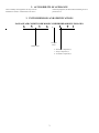
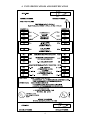
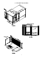
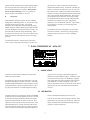
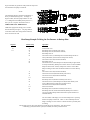
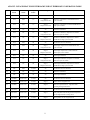
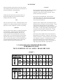
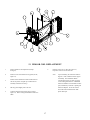
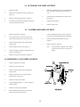
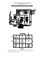
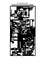
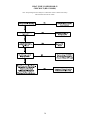
SERVICE MANUAL
FOR
6536 “-” AND “A” SERIES
TWO TON PACKAGED HEAT PUMPS
TABLE OF CONTENTS
1.
2.
3.
4.
5.
6.
7.
8.
9.
10.
11.
12.
13.
14.
15.
16.
17.
18.
18A.
19.
19A.
20.
21.
Warnings . . . . . . . . . . . . . . . . . . . . . . . . . . . . . . . . . . . . . . . . . . . . . . . . . . . . . . . . . . . . . . . . . .
Accessibility Of Appliance . . . . . . . . . . . . . . . . . . . . . . . . . . . . . . . . . . . . . . . . . . . . . . . . . . . .
Unit Dimensions And Specifications . . . . . . . . . . . . . . . . . . . . . . . . . . . . . . . . . . . . . . . . . . . .
Specifications And Unit Identification . . . . . . . . . . . . . . . . . . . . . . . . . . . . . . . . . . . . . . . . . .
Unit Depiction Figures . . . . . . . . . . . . . . . . . . . . . . . . . . . . . . . . . . . . . . . . . . . . . . . . . . . . . . .
Thermostat Specifications . . . . . . . . . . . . . . . . . . . . . . . . . . . . . . . . . . . . . . . . . . . . . . . . . . . .
Wall Thermostat - 6536-335* . . . . . . . . . . . . . . . . . . . . . . . . . . . . . . . . . . . . . . . . . . . . . . . . .
Thermostat Control Panel . . . . . . . . . . . . . . . . . . . . . . . . . . . . . . . . . . . . . . . . . . . . . . . . . . . .
Blower Performance Chart . . . . . . . . . . . . . . . . . . . . . . . . . . . . . . . . . . . . . . . . . . . . . . . . . . .
Indoor Blower Motor Removal . . . . . . . . . . . . . . . . . . . . . . . . . . . . . . . . . . . . . . . . . . . . . . . .
Outdoor Blower Motor Removal . . . . . . . . . . . . . . . . . . . . . . . . . . . . . . . . . . . . . . . . . . . . . . .
By Flow Restrictor Replacement . . . . . . . . . . . . . . . . . . . . . . . . . . . . . . . . . . . . . . . . . . . . . . .
Evaporator Coil Replacement . . . . . . . . . . . . . . . . . . . . . . . . . . . . . . . . . . . . . . . . . . . . . . . . . .
Condenser Coil Replacement . . . . . . . . . . . . . . . . . . . . . . . . . . . . . . . . . . . . . . . . . . . . . . . . . .
Compressor Replacement . . . . . . . . . . . . . . . . . . . . . . . . . . . . . . . . . . . . . . . . . . . . . . . . . . . . .
Reversing Valve Replacement . . . . . . . . . . . . . . . . . . . . . . . . . . . . . . . . . . . . . . . . . . . . . . . . . .
Wiring Diagram - Electronic Thermostat . . . . . . . . . . . . . . . . . . . . . . . . . . . . . . . . . . . . . . . .
Wiring Diagram . . . . . . . . . . . . . . . . . . . . . . . . . . . . . . . . . . . . . . . . . . . . . . . . . . . . . . . . . . . . .
Wiring Diagram . . . . . . . . . . . . . . . . . . . . . . . . . . . . . . . . . . . . . . . . . . . . . . . . . . . . . . . . . . . . .
Wirebox Component Checkout (6536 Models) . . . . . . . . . . . . . . . . . . . . . . . . . . . . . . . . . . . .
Wirebox Component Checkout (6536A Models) . . . . . . . . . . . . . . . . . . . . . . . . . . . . . . . . . . .
Service Problems And Possible Solutions . . . . . . . . . . . . . . . . . . . . . . . . . . . . . . . . . . . . . . . . .
Electrical Flow Charts . . . . . . . . . . . . . . . . . . . . . . . . . . . . . . . . . . . . . . . . . . . . . . . . . . . . . . . .
A.
Cooling Mode . . . . . . . . . . . . . . . . . . . . . . . . . . . . . . . . . . . . . . . . . . . . . . . . . . . . . . . .
B.
Heating Mode . . . . . . . . . . . . . . . . . . . . . . . . . . . . . . . . . . . . . . . . . . . . . . . . . . . . . . . .
2
2
3
4
5
6
7
10
11
12
13
16
17
18
18
18
19
20
21
22
23
24
25
26
34
1. WARNINGS
IMPORTANT NOTICE
WARNING - SHOCK HAZARD
These instructions are for the use of qualified individuals
specially trained and experienced in installation of this type
equipment and related system components.
To prevent the possibility of severe personal injury or
equipment damage due to electrical shock, always be sure the
electrical power to the appliance is disconnected.
Installation and service personnel are required by some states
to be licensed. PERSONS NOT QUALIFIED SHALL NOT
INSTALL NOR SERVICE THIS EQUIPMENT.
CAREFULLY FOLLOW ALL INSTRUCTIONS AND
WARNINGS IN THIS BOOKLET TO AVOID DAMAGE TO
THE EQUIPMENT, PERSONAL INJURY OR FIRE.
NOTE
WARNING
The words “Shall” or “Must” indicate a
requirement which is essential to satisfactory
and safe product performance.
Improper installation may damage equipment, can create a
hazard and will void the warranty.
The use of components not tested in combination with these
units will void the warranty, may make the equipment in
violation of state codes, may create a hazard and may ruin the
equipment.
The words “Should” or “May” indicate a
recommendation or advice which is not
essential and not required but which may
be useful or helpful.
2
2. ACCESSIBILITY OF APPLIANCE
The accessibility of this appliance will vary from one
installation to another. It shall be left to the service
technicians judgement, the best method of attaining access to
perform service.
3. UNIT DIMENSIONS AND SPECIFICATIONS
PACKAGE AIR CONDITIONER MODEL NUMBER BREAKDOWN FOLLOWS:
6
5
3
6
-
8
9
Revision
Letter
Model Series
6 - Panasonic Compressor(s)
7 - Sanyo Compressor(s)
8 - Tecumseh Compressor(s)
3
1
4. UNIT SPECIFICATIONS AND IDENTIFICATION
4
5. UNIT DEPICTION FIGURES
5
6. THERMOSTAT SPECIFICATIONS
THERMOSTAT - 6795B3451
SUB-BASE - 7330-3401
SET TEMP. RANGE:
55 TO 90 DEGREES F.
DISPLAY TEMPERATURE:
-20 TO 160 DEGREES F.
SCALE:
DEGREES FAHRENHEIT
DISPLAY FORMAT:
LIQUID CRYSTAL DISPLAY
RESOLUTION:
ONE DEGREE F.
ACCURACY:
± 2% OF DISPLAY TEMPERATURE RANGE
SAMPLING RATE:
EVERY 30 SECONDS
POWER SOURCE:
12 VDC NON-REGULATED, NON-FILTERED ± 2 VOLTS
OPERATING TEMPERATURE:
-10 TO +55 DEGREE C.
OUTPUT LOAD:
40 mA MINIMUM TO 1.5 AMP MAXIMUM FOR EACH OUTPUT
SAFEGUARDS:
STATIC ELECTRICITY PROTECTION TO END USER AFTER INSTALLATION
ANTI-STATIC PACKAGING TO BE USED FOR SHIPMENT
SPIKE PROTECTION TO 400 VDC ON R+ TERMINAL
CONFORMAL COATING ON P.C. BOARD PROTECTION FROM MOISTURE
DEFAULT MODE:
WHEN THE THERMOSTAT IS SWITCHED TO HEAT AND ELECTRIC HEAT IS
SELECTED ON THE SUB-BASE, AND THE OUTDOOR TEMPERATURE FALLS
TO A POINT AT WHICH THE HEAT PUMP SHUTS DOWN (USUALLY BETWEEN
25 - 40 DEGREES), THE SUB-BASE WILL AUTOMATICALLY ALSO CALL FOR GAS
FURNACE OPERATION IF THE INDOOR TEMPERATURE DROPS TO 45 DEGREES.
GAS FURNACE OPERATION WILL SHUT OFF AT 60 DEGREES. THE USER SHOULD SWITCH
THE SUB-BASE TO GAS HEAT IF THIS OCCURS.
GENERAL INFORMATION
A.
Air Conditioner
This packaged heat pump mounts below the floor of the
vehicle. The innovative design makes it possible to maintain a
smooth, free-flowing roof line for the vehicle. It also relocates
all noise and condensate drainage off the roof to below the
floor of the vehicle.
1)
The thermostat is demanding cooling or electric
heating,
2)
The vehicle is being powered by either shore line or
the on-board generator.
2nd stage (the second compressor and refrigeration circuit), will
operate when:
The heat pump contains a dual compressor system. It
combines the capacity of two roof mounted units into one
highly efficient and compact package.
Each compressor is connected to a separate refrigeration
circuit. The system can be operated with a single compressor
when the air conditioning requirement is low, or with two
compressors when maximum performance is required.
This heat pump operates a two-stage system. The first
compressor and refrigeration circuit is referred to as “1st
Stage”. The second compressor and refrigeration circuit is
referred to as “2nd Stage”. First and second stage will operate
as indicated below.
1)
The thermostat senses room temperature that is 2
degrees or higher than the setpoint temperature on
the thermostat,
2)
The vehicle is being powered by the on-board
generator. Shore line by itself will not provide
enough power to operate both first and second stage
unless 50 amp service is available.
Switching and control of 1st and 2nd stage cooling is automatic.
When operating from shore line, the system automatically
limits operation to 1st stage only unless 50 amp service is
available. When the shore line is plugged into the on-board
generator, the system automatically allows for operation of
both 1st and 2nd stage units. However, if when powering both
1st stage (the first compressor and refrigeration circuit), will
operate when:
6
systems from the on-board generator and the cooling demand
does not require that both systems operate, stage two will
shut down leaving stage one in operation. Heat operation
always energizes both stages, however, only stage one
operates if power is not available to circuit #2.
B.
the compressors. This is to allow time for generators to
stabilize when initially starting. The balance of the delay (2.5
minutes) occurs when the compressors cycle off. This is to
allow time for the air conditioner pressures to balance before
restarting. This delay will eliminate problems associated with
short cycling and will extend equipment life. There is thirty
seconds and two degrees between 1st and 2nd stage cooling.
The thermostat will not call for 2nd stage cooling until room
temperature rises 2 degrees above the 1st stage starting
temperature. Once the thermostat calls for 2nd stage cooling, a
30 second delay is incurred to prevent both stages from
starting together.
Thermostat
This thermostat is designed to operate 12 VDC controlled
heating and air conditioning systems. It can control one stage
of heating and two stages of cooling. It is a manual
changeover type of thermostat between heating and cooling.
Manual changeover indicates that the operator must manually
switch the thermostat from cooling operation to heating. The
thermostat will not make this change automatically. It also
incorporates time delay circuitry. The user selectable heating
mode on the sub-base allows gas heat control or heat pump
operation.
The operating setpoints are changeable to suit the comfort
needs of the occupants. Instructions for setting operating
temperatures (the setpoints) are covered in “Adjusting
Setpoint”.
The time delays amount to 3 minutes between off and on
cycles. Thirty seconds of this time delay is at the turn on of
7. WALL THERMOSTAT - 6536-335*
A. APPLICATION
The 6536-335* thermostat is intended for use with an RV
Products 2 stage heat pump.
receptacle for the 3 pin plug. RV Products suggests the
thermostat wiring be minimum 18 gauge. The furnace control
circuit must not exceed 1 amp. The thermostat is equipped
with a replaceable fast-acting 2 amp fuse located on the base
of the thermostat. The fuse is designed to “open” if the
furnace is mis-wired or if there is a short in the system. Before
replacing fuse, the cause of the failure must be located and
corrected.
The thermostat connects to the heat pump with a 9 pin plug
through a lifeline (RVP part number 6795C4351). The OEM
(Original Equipment Manufacturer) must supply the 12 VDC
wiring and the furnace control wiring which connects to the 3
pin plug on the thermostat. The OEM supplies the mating
B. OPERATION
The display indicates room temperature and the word ROOM
is shown on the LCD until the temperature selector is pressed;
at which time the display temporarily indicates the setpoint
temperature and the word SET is shown on the LCD. Each
time the UP arrow is pressed, the setpoint will increase. Each
time the DOWN arrow is pressed, the setpoint will decrease.
Once the temperature selector button is no longer pressed for
a few seconds, the room temperature will again be displayed,
and the word ROOM will be displayed on the LCD.
In the electric heat mode, if the heat pump is unable to satisfy
the thermostat, the heat pump goes into lockout. DIFF will
display on the thermostat LCD indicating backup heating is
required to satisfy the thermostat.
7
In gas heat mode, the gas furnace will provide the only source
of heat and the heat pump is locked out.
NOTE
The temperature displays in degrees Fahrenheit as a
factory set default (See Figure 2). To display in
degrees Celsius, move the jumper marked “F” and
“C” to bridge between middle pin and position “C”,
then cycle 12 volt power off and then back on.
WIRING THE WALL THERMOSTAT
OEM must supply these mating parts to connect
these thermostats per Figure 1. The plugs must be
connected to motorcoach wiring harness before the
base is secured to the wall.
Heat Pump Example To Bring On Gas Furnace As Backup Heat
Setpoint
70
\\\
Indoor Temp.
70+
69
71
69
65
71
69
65
71
69
71
\\\
69
65
71
\\\
69
71
Operation
No functions occur
Heat Pump turns on (Primary heat source)
Heat Pump turns off (Thermostat satisfied)
Heat Pump turns on
Gas Furnace turns on, Heat Pump turns off (Heat Pump not able to
satisfy Thermostat) (First strike for backup heat counter)
Gas Furnace turns off (Thermostat satisfied)
Heat Pump turns on
Gas Furnace turns on, Heat Pump turns off (Heat Pump is again unable
to satisfy Thermostat), (Backup heat counter reaches 3rd strike and Heat
Pump is locked out for 2 hours), backup heat counter is reset if Heat
Pump is running for more than 20 minutes and does not call for backup
heat
Gas Furnace turns off (Thermostat satisfied)
Gas Furnace turns off (Becomes Primary heat source)
Gas Furnace turns off (Thermostat Satisfied)
After 2 hour lockout
Heat Pump turns on (Resumes as Primary heat source)
Gas Furnace turns on, Heat Pump turns off (Becomes Primary heat
source) (Heat Pump is locked out for another 2 hours)
Gas Furnace turns off (Thermostat Satisfied)
After 2 hour lockout
Heat Pump turns on (Resumes as Primary heat source)
Heat Pump turns off (Thermostat Satisfied) (Backup heat counter is
reset any time Heat Pump satisfies thermostat setpoint and does not
need Gas Furnace)
The word “DIFF” will display on LCD when backup heat is operating
and the heat pump is locked out. There is a 30 second delay between
Stage 1 and Stage 2. There is also a 3 minute anti-short cycle delay time
for cooling.
The chart below shows the system functions with the 6536-335* thermostat. After the entire air
conditioning system (and furnace system) is installed, check each position function.
8
6536-335* 2-STAGE HEAT PUMP WITH BACKUP HEAT THERMOSTAT OPERATION TABLE
Mode
Switch
Fan Mode
Switch
Fan Speed
Switch
Calling
1
Cool
Auto
Lo
No
2
Cool
Auto
Lo
Stage 1
1 Degree Above Set
ID fan low, compressor #1 and OD blower low
cycle as needed
3
Cool
Auto
Lo
Stage 2
2 Degrees Above Set
ID fan low, compressors #1 and #2 and OD blower
high cycle as needed
4
Cool
On
Lo
No
5
Cool
On
Lo
Stage 1
1 Degree Above Set
ID fan low continuous, compressor #1 and OD
blower low cycle as needed
6
Cool
On
Lo
Stage 2
2 Degrees Above Set
ID fan low continuous, compressors #1 and #2
and OD blower high cycle as needed
7
Cool
Auto
Hi
No
8
Cool
Auto
Hi
Stage 1
1 Degree Above Set
ID fan high, compressor #1 and OD blower low
cycle as needed
9
Cool
Auto
Hi
Stage 2
2 Degrees Above Set
ID fan high, compressors #1 and #2 and OD
blower high cycle as needed
10
Cool
On
Hi
No
11
Cool
On
Hi
Stage 1
1 Degree Above Set
ID fan high continuous, compressor #1 and OD
blower low cycle as needed
12
Cool
On
Hi
Stage 1
2 Degrees Above Set
ID fan high continuous, compressors #1 and #2
and OD blower high cycle as needed
13
Off
Auto
Lo or Hi
No
No functions occur in this mode
14
Off
On
Lo
No
ID fan low continuous
15
Off
On
Hi
No
ID fan high continuous
16
Gas Heat
Auto or On
Lo or Hi
No
No functions occur in this mode
17
Gas Heat
Auto or On
Lo or Hi
Stage 1
Heater will be energized to run
18
Gas Heat
Auto or On
Lo or Hi
Stage 2
There is no provision for 2nd stage heat when
operating in the gas heat mode
19
Elec Heat
Auto or On
Lo or Hi
No
20
Elec Heat
Auto or On
Lo or Hi
Stage 1
Heat pump will run ID fan high, both compressors,
OD fan high and both reversing valves
21
Elec Heat
Auto or On
Lo or Hi
Stage 2
Backup heater will be energized to run
9
Operation
No functions occur in this mode
ID fan low continuous
No functions occur in this mode
ID fan high continuous
No functions occur in this mode
8. THERMOSTAT CONTROL PANEL
A. OPERATION
Your air conditioner is operated from the control panel located
on the electronic wall mounted thermostat. When the furnace
is connected to this thermostat, it will be operated from the
same control panel.
3.
Identification and operational descriptions for all control panel
switches and display are listed below:
1.
2.
Liquid Crystal Display - We will start with the display
because the display will be visible any time the
system is in operation. The display will remain visible
while the thermostat is on and powered.
Cooling Fan Switch - The fan switch has four
positions from which to control the operation of the
cooling blower. The fan switch controls operation of
the cooling blower only after the system switch is
placed into the COOL position. With the system
switch in any other position, the fan switch will have
no effect on the operation of the cooling blower. Fan
switch positions and their resulting function are
listed below:
HIGH AUTO - When in the high automatic position,
the cooling blower operates at high speed and cycles
off and on with the 1st stage compressor. 2nd stage
cooling will cycle on and off as needed having no
effect on cooling blower operation.
System Switch - The system switch has four
positions to control the operation of the heating and
air conditioning systems. They are as follows:
LOW AUTO - When in the low automatic position,
the cooling blower operates at low speed and cycles
off and on with the 1st stage compressor. 2nd stage
cooling will cycle on and off as needed having no
effect on cooling blower operation.
COOL - When in the cool position, 1st and 2nd stage
cooling will cycle from the cooling system setpoint.
Blower operation will be controlled by the position
of the Cooling Fan Switch.
HEAT - When in the heat position, the heating
system will cycle from the heating system setpoint.
Heat will be by electricity (heat pump) or gas as
selected on sub-base. The gas heating blower will
operate per the heating system manufacturer
specifications.
LOW ON - When in the low on position, the cooling
blower operates continuously at low speed. Stage 1
and Stage 2 compressors cycle on and off as needed.
HIGH ON - When in the high on position, the
cooling blower operates continuously at high speed.
Stage 1 and Stage 2 compressors cycle on and off as
needed.
OFF - When in the off position, no thermostat or
system operation will occur.
During heat pump operation, the blower operates at
high speed with heat demand.
FAN - When in the fan position, the cooling blower
will operate continuously at high speed.
10
B. TESTING
Place the thermostat system switch into the “OFF” position.
Once all safety precautions have been met, reinstate power to
all systems; thermostat, cooling and heating.
COOLING
Move the system switch to COOL. The display will indicate
room temperature. Adjust the setpoint above room
temperature. Move the fan switch to LOW ON. The fan
operates continuously at low speed.
OFF
Starting with the system switch in the OFF position, the
display will be blank and no part of either the cooling or
heating systems will be operating.
Move the fan switch to HIGH ON. The fan operates
continuously at high speed. Move the fan switch to LOW
AUTO, the fan will stop. Move the fan switch to HIGH
AUTO, the fan will remain off.
FAN
Move the system switch to FAN. The display indicates room
temperature. The cooling system fan operates continuously at
high speed. No other components or systems are operating.
Adjust the setpoint 5 degrees below room temperature (if the
thermostat has been powered for more than 3 minutes, 1st stage
cooling and the cooling fan will come on approximately 1
minute later). If the thermostat has not been powered for more
than 3 minutes, 1st stage cooling and the cooling fan will come
on anywhere from 30 seconds to 3 minutes later. 2nd stage
cooling will come on approximately 30 seconds after the 1st
stage.
HEATING
Move the system switch to HEAT. The display will indicate
room temperature. Adjust the setpoint of the thermostat
above the room temperature displayed. After 15 to 30
seconds, the heat circuit of the thermostat will activate the
heating controls. Once the heat has turned on and is running,
adjust the setpoint below the room temperature displayed.
After 15 to 30 seconds, the heat circuit of the thermostat will
turn off and deactivate the heating controls. In heat pump
operation, indoor fan operates on only high speed .
With the fan switch in HIGH AUTO, the fan will operate at
high speed and cycle with stage 1 compressor. Move the fan
switch to LOW AUTO. The fan will operate at low speed and
cycle with stage 1 compressor. Once both stages of cooling
and both fan speeds have been verified, adjust setpoint 1
degree below room temperature. After 15 to 30 seconds, 2nd
stage cooling will turn off while 1st stage remains on.
9. PACKAGED AIR CONDITIONER BLOWER
PERFORMANCE DATA
TEST CONDITION: 115 VAC, 60 HZ, 1 PHASE, DRY COIL
CHART 1
11
10. INDOOR BLOWER MOTOR
REMOVAL
1.
Remove indoor blower access panel.
5.
Remove motor assembly from scroll.
2.
Disconnect wiring from motor terminal block and
capacitor.
6.
Remove blower wheel and motor mounting bracket.
3.
Remove 4 screws from venturi (See #1, Figure 7).
4.
Remove 3 screws from motor mount bracket
(See #2, Figure 7).
Note:
Upon reassembly, the references made on
Figures 7 and 8 shall be used for proper
reassembly.
SIDE VIEW
Section 1.
Position motor with terminal block parallel to motor mount leg opposite motor clamp. Assemble motor mount into
scroll in orientation shown.
Section 2.
Torque nut to 65 in. lbs. min.
Section 3.
Ground wire terminal assemblies between screw head and washer.
Section 4.
Motor rotation wires to be connected: Yellow to Yellow and Orange to Orange.
Section 5.
Alternate capacitor: 1499-546
Section 6.
Bundle the rotation and capacitor wires up and wire tie together.
12
END VIEW
1.
Wheel must be mounted with a minimum of 5/16"
clearance to scroll sides.
2.
Apply grease to motor shaft before assembling
wheel.
3.
Torque set screw on flat of shaft to 110 #10 in. lbs.
11. OUTDOOR BLOWER MOTOR REMOVAL
1.It will be necessary to remove the top panel of the unit.
6.
Remove 4 screws from venturi (See #1, Figure 10).
1.
Remove 4 screws that attach scroll housing to
basepan (See #1, Figure 9).
7.
Remove 4 screws from motor mount bracket
(See #2, Figure 10).
2.
Disconnect wiring from motor terminal block.
8.
Remove motor assembly from scroll.
3.
Remove scroll/motor assembly from the unit.
9.
Remove blower wheel and motor mounting bracket.
4.
If at this point only the blower wheel needs replaced,
then remove 4 screws from inboard venturi. Remove
and replace blower wheel (see note) or else go to
Step 6.
Note:
Upon reassembly, the references made on
Figures 9 and 10 shall be used for proper reassembly.
5.
Disconnect wiring at capacitor.
13
BOTTOM VIEW
1.
Wheel must be mounted with a minimum of 1/4" clearance to both venturis.
2.
Apply grease to motor shaft before assembling wheel.
3.
Torque set screw on flat of shaft to 110 #10 in. lbs.
14
SIDE VIEWS
1.
Position motor with terminal block opposite motor mount clamp.
2.
Torque nut to 65 in. lbs. min.
3.
Ground wire terminal assembles between screw head and washer.
Wrap wire around motor mount leg to take up slack.
4.
Wire tie capacitor wires to mount leg.
15
12. BY-FLOW RESTRICTOR REPLACEMENT
1.
Remove top panel.
2.
Remove Section C (See Figure 11).
3.
Remove outdoor blower. Follow steps 1-4 in Outdoor
Blower Motor Removal Section.
4.
Be certain at this point that the refrigerant charge has
been removed from the system/systems being
serviced.
5.
Remove clamps holding restrictor in place
(See #17, Figure 12).
6.
Unbraze by-flow restrictor from points 16. Make note
of plumbing locations for new restrictor. Must be
installed in same manner. (Note to protect any wiring
that could come into contact with the torch flame or
heated copper lines.)
Note:
16
Upon reassembly, the references made on
Figures 11 and 12 shall be used for proper
reassembly. The assemblies shall be
secured with wire ties in order to prevent
excess chafing and vibration.
13. INDOOR COIL REPLACEMENT
1.
Refer to Outdoor Coil Replacement (Steps 1
through 7).
2.
Remove screws from bottom of step panel (See #6,
Figure 12).
3.
Remove freeze thermister located on indoor blower
side of evaporator coil (pull top of indoor blower
assembly outward if necessary).
4.
Pull step panel slightly off to one side.
5.
Unbraze refrigerant from points (See #1 and #5,
Figure 12). Protect wiring and insulation from torch
flame.
6.
Remove screws (See #7, #8 & #9, Figure 12).
Evaporator coil can now be removed.
Note:
17
Upon reassembly, the references made on
Figures 11 and 12 shall be used for proper
reassembly. The assemblies shall be
secured with wire ties in order to prevent
excess chafing and vibration. If additional
sealant is needed to seal coil header to drain
pan (notched end), a silicone or perma-gum
sealant is adequate. Do not use solvent
base sealers that would harm the ABS
plastic drain pan.
14. OUTDOOR COIL REPLACEMENT
1.
Remove top panel.
2.
Remove screws along wirebox side of coil (See #10,
Figure 12).
3.
Remove corner panel (See Section C, Figure 11).
4.
Be certain at this point that the refrigerant charge has
been removed from the systems.
5.
Make note of plumbing locations. The plumbing will
have to go back to the same locations on the new
coil.
6.
Unbraze discharge and liquid lines at points #2 and
#4, Figure 12.
7.
Remove freeze thermister.
8.
Remove condenser coil.
15. COMPRESSOR REPLACEMENT
1.
Remove compressor access panel.
7.
Unbraze plumbing at points #11 and #12, Figure 12
(protect any wiring and insulation from torch flame).
2.
The top panel may be removed at this point if it
allows technician better access to perform service.
8.
Remove mounting nuts and washers (See #14,
Figure 12).
Remove refrigerant charge from system/systems
being serviced.
9.
Remove compressor from unit.
3.
4.
Remove terminal caps (See #13, Figure 12).
5.
Remove wiring from compressor terminal block (cut
wire ties on suction line).
6.
Remove reversing valve clamp from compressor.
Note:
16. REVERSING VALVE REPLACEMENT
1.
Remove compressor access panel.
2.
Remove top panel at this point.
3.
Remove refrigerant charge from system/systems
being serviced.
4.
Remove outdoor blower. See Outdoor Blower
Removal Steps 1-4 on page 11.
5.
Remove reversing valve solenoid.
6.
Unbraze plumbing points at 1, 2, 3 & 4 in Figure 13
(Protect wiring).
7.
Remove reversing valve from bracket.
8.
When reinstalling reversing valve, wrap the valve
body with a wet rag as best you can.
18
Upon reassembly, compressor wires shall be
wire tied to suction lines to prevent excess
chafing.
17. WIRING DIAGRAMS - THERMOSTAT
Diagram 1976E119
Electronic Wall Thermostat Assembly (12 VDC) - 6536-3451
Thermostat plug positions on the p.c. board. If no voltage is detected at the p.c. board connector,
check for voltage at the thermostat. Note: All functions of this heat pump are subject to thermostat
time delays according to the operation manual.
19
18. WIRING DIAGRAM
6536 Series Two Ton Packaged Heat Pump - 2 Compressor
20
18A. WIRING DIAGRAM
6536A Series Two Ton Packaged Heat Pump
21
19. WIREBOX COMPONENT CHECKOUT
6536 “-” MODEL
22
19A. WIREBOX COMPONENT CHECKOUT
6536 “A” MODELS
23
20. SERVICE PROBLEMS AND POSSIBLE SOLUTIONS
COOLING MODE
Problems
Possible Solutions
1.
Nothing Runs - Cooling Mode
No A/C Voltage, No 12 VDC, Thermostat, Wiring, P.C. Board
2.
IDFM Runs, No Compressor, No ODFM
Cooling Freeze Thermistor - (Insufficient Indoor Air Flow),
Thermostat, Wiring, Compressor, Contactor, P.C. Board
3.
IDFM Runs, ODFM Runs, No Compressor
Insufficient Voltage To Unit, Run Capacitor, Start Device,
Overload, Wiring, Compressor
4.
IDFM Runs, Compressor Runs, No ODFM
5.
Compressor Runs, ODFM Runs, No IDFM
6.
Compressor, ODFM, IDFM Runs, Insufficient
Cooling
7.
Compressor, ODFM, IDFM Runs, Unit Is Heating
While In Cool Mode
Run Capacitor, Fan Motor, P.C. Board, Wiring
Thermostat, Run Capacitor, Wiring, Fan Motor, P.C. Board
Air Flow Restriction, High Ambient Temperature, Undersized
Refrigeration System, Very Little Or No Refrigerant Charge,
Compressor
Thermostat, Wiring, P.C. Board, Reversing Valve
HEATING MODE
Problems
Possible Solutions
1.
Nothing Runs - Heat Mode
No A/C Voltage, No 12 VDC, Thermostat, Sub-base, Wiring,
P.C. Board
2.
IDFM Runs, No Compressor, No ODFM
Heating Freeze Thermister, Low Outdoor Ambient Conditions,
Wiring, Compressor, Contactor, P.C. Board
3.
IDFM Runs, ODFM Runs, No Compressor
Insufficient Voltage To Unit, Run Capacitor, Start Device,
Overload, Wiring, Compressor
4.
IDFM Runs, Compressor Runs, No ODFM
Run Capacitor, Fan Motor, Wiring, P.C. Board
5.
Compressor Runs, ODFM Runs, No IDFM
Run Capacitor, Fan Motor, Wiring, P.C. Board
6.
Compressor Runs, ODFM Runs, IDFM Runs,
Insufficient Heating
Air Flow Restriction, Low Ambient Temperature, Undersized
Refrigeration System, Very Little Or No Refrigerant Charge,
Compressors
7.
Compressor, ODFM, IDFM, Unit Is Cooling While In
Heat Mode
Wiring, P.C. Board, Reversing Valve
24
21. ELECTRICAL FLOW CHARTS
6536 SERIES
With the use of these flow charts, you will be able to quickly
identify a non-working problem. Determine if the problem is
high or low voltage and then solve the problem.
To use these flow charts, start at the top left corner. Using a
volt-ohm meter, check what is indicated in that box. If the
answer to what is indicated is No, work horizontally until you
find the problem. When the answer is Yes or OK, work the
chart downward until you locate the problem. Do Not Move
Downward on any chart until all preceding steps have been
confirmed good. Do Not start in the middle of any chart
without knowing everything previous (upward on the chart) is
OK or you may replace the wrong part.
IMPORTANT NOTICE
When using a jumper wire to diagnose
a low voltage problem, Never Short
Any Positive Terminal to Ground or
the Terminal Marked “B”. Serious
thermostat or p.c. board damage may
occur.
25
A. 6536 SERIES OPERATION SEQUENCE
COOLING MODE
26
COOLING MODE
CHECK/NO GREEN L.E.D. LIGHT
FY/Y CIRCUIT TO THE THERMOSTAT
Note:
The green light on the 6536A model has some new functions:
1.
2.
3.
If the light is on solid, then everything is OK.
If the light is blinking slowly, the unit is in a 3 minute time delay.
If the light is blinking fast, there is either no line voltage to Circuit #1
or one of the thermistors are open.
27
I.D. BLOWER LOW SPEED
THERMOSTAT ON LOW FAN
COOL ONLY
Note: All operating functions subject to thermostat time delays.
28
I.D. BLOWER HIGH SPEED
THERMOSTAT ON HIGH FAN
COOL ONLY
Note: All operating functions subject to thermostat time delays.
29
COMPRESSOR #1 CHECKOUT
THERMOSTAT CALLING FOR COMPRESSOR
COOLING ONLY
Note: All operating functions subject to thermostat time delays.
30
COMPRESSOR #2 CHECKOUT
THERMOSTAT CALLING STAGE 2
COOLING ONLY
Note: All Operating Functions Subject To Thermostat Time Delays
31
CHECKOUT OUTDOOR BLOWER
LOW SPEED
HEATING AND COOLING MODES
32
CHECKOUT OUTDOOR BLOWER
HIGH SPEED
HEATING AND COOLING MODES
33
B. 6536 SERIES OPERATION SEQUENCE
HEATING MODE
34
HEAT/MODE CHECKOUT/NO GREEN L.E.D. LIGHT
F/F CIRCUIT TO THE THERMOSTAT
35
HEAT MODE
I.D. BLOWER CHECKOUT
Note: High Fan Speed Is Energized Only.
All Operating Functions Subject To Thermostat Time Delays.
36
COMPRESSOR #1 CHECKOUT
HEAT MODE
Note: All Operating Functions Subject To Thermostat And P.C. Board Time Delays.
Sub-base Must Be In The Electric Mode.
37
HEAT PUMP COMPRESSOR #2
CHECKOUT (HEAT MODE)
Note: All Operating Functions Subject To Thermostat And P.C. Board Time Delays.
Sub-base Must Be In Electric Mode.
38
REVERSING VALVE CHECKOUT
HEAT MODE
Note: Reversing Valve Is Energized In The Heat Mode And Is Subject To
Thermostat And P.C. Board Time Delays.
Note: If Compressor And Fan Motors Not Running, Refer To Proper Checkouts.
Once The Reversing Valve Has Energized, The P.C. Board Locks The Valve
Into An Energized Position Until The Wall Thermostat Is Put In The Cool
Position And Actually Has A Demand For Cooling, Sending 12 VDC Down Y1.
39
RV Products
A Division of Airxcel, Inc.
P.O. Box 4020
Wichita, KS 67204
1976C281 (8-05) PP