1
Xmedia Suite 4.00
Configuration Guide
M856-0200-400
Xmedia Suite v4.0
Vertigo XG
Advanced HD/SD Graphics Processor
(Single/Dual Channel)
Configuration Guide
Copyright Notice
© 2008 Miranda Technologies Inc. All rights reserved.
Third Party Trademarks
All other brand names, product names or trademarks belong to their respective holders.
Usage Agreement
Please read the following terms and conditions carefully. By using the Vertigo XG
Configuration Guide, you agree to the following terms and conditions:
Miranda Technologies Inc. hereby grants permission and license to owners of Vertigo XG
and Xmedia Suite to use their product manuals for their own internal business use. Manuals
for Miranda Technologies Inc. products may not be reproduced or transmitted in any form
or by any means, electronic or mechanical, including photocopying and recording, for any
purpose unless specifically authorized in writing by Miranda Technologies Inc.
Miranda Technologies Inc. makes no warranty, either expressed or implied, including but
not limited to any implied warranties of merchantability or fitness for a particular purpose,
regarding these materials and makes such materials available solely on an “As-Is” basis.
In no event shall Miranda Technologies Inc. be liable to anyone for special, collateral,
incidental, or consequential damages in connection with or arising out of purchase or use
of these materials. The sole and exclusive liability to Miranda Technologies Inc., regardless
of the form of action, shall not exceed the purchase price of the materials described herein.
Miranda Technologies Inc. reserves the right to revise and improve its products at any time
and without notice. This publication describes the state of this product at the time of its
publication, and may not reflect the product at all times in the future. Thus, different versions
of a manual may exist for any given product. Care should be taken to ensure that one
obtains the proper manual version for a specific product serial number.
Information in this document is subject to change without notice and does not represent a
committment on the part of Miranda Technologies Inc.
Government Use
The Software {and Documentation} is provided with RESTRICTED RIGHTS. Use,
duplication or disclosure by the United States Government or any agency, department or
instrumentality thereof is subject to the restrictions set forth in the Commercial Computer
Software -- Restricted Rights clause at FAR 52.227-19 or the Commercial Computer
Software -- Licensing clause at NASA FAR Supplement 1852.227-86.
Printed in Canada
Document Identification
•
Title: Vertigo XG Configuration Guide
•
Part number: M856-0200-400
•
Software version: Xmedia Suite v.4.0
•
Last revised: April 3, 2008
TABLE OF CONTENTS
Introduction .......................................................................................................................... 1-1
About the Vertigo XG......................................................................................................................... 1-2
Key Features ..................................................................................................................................... 1-4
Licensing Information.................................................................................................................... 1-5
Preliminary Guidelines and Recommendations................................................................................. 1-7
Vertigo XG Recommended Media Formats .................................................................................. 1-7
Vertigo XG Virus Protection Guidelines ...................................................................................... 1-10
Publish Path Coordination Guidelines ........................................................................................ 1-13
Vertigo XG Hardware ........................................................................................................... 2-1
Vertigo XG Chassis Overview ........................................................................................................... 2-3
Vertigo XG Signal Path and Rendering Processes ........................................................................... 2-5
Video Input/Output Channels........................................................................................................ 2-6
Audio Input/Output Channels........................................................................................................ 2-7
Ancillary Data Processing ............................................................................................................. 2-8
Graphics Processing..................................................................................................................... 2-8
Media Storage .............................................................................................................................. 2-9
Clip Player .................................................................................................................................. 2-10
VertigoXG and Renderer Windows..................................................................................... 3-1
VertigoXG Window ............................................................................................................................ 3-2
XG Renderer Window........................................................................................................................ 3-3
XG Dashboard - Vertigo XG’s Configuration Software..................................................... 4-1
About XG Dashboard ........................................................................................................................ 4-2
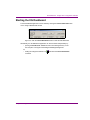
Starting the XG Dashboard ............................................................................................................... 4-3
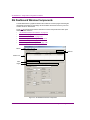
XG Dashboard Window Components................................................................................................ 4-4
XG Dashboard Menus and Buttons ................................................................................................... 4-5
Device List ......................................................................................................................................... 4-7
Loading and refreshing the device list .......................................................................................... 4-8
Saving the device list .................................................................................................................... 4-8
Restarting a device in the device list............................................................................................. 4-9
Monitoring the status of a device .................................................................................................. 4-9
Removing a device from the device list ........................................................................................ 4-9
General Information Tab.................................................................................................................. 4-10
Device Settings Tab and Pages ...................................................................................................... 4-12
Device Settings Tab Buttons ...................................................................................................... 4-13
General Page.............................................................................................................................. 4-14
Resolution Page ......................................................................................................................... 4-16
Live Window Page ...................................................................................................................... 4-18
Clips Page .................................................................................................................................. 4-20
3D Engine Page.......................................................................................................................... 4-22
Logging Page.............................................................................................................................. 4-24
AV Input Page............................................................................................................................. 4-26
Vertigo XG Configuration Guide
TOC-1
Table of Contents
Licensing Page ............................................................................................................................4-27
Genlock Page ..............................................................................................................................4-28
Video Page ..................................................................................................................................4-31
Audio Page ..................................................................................................................................4-33
Watch Dog Page..........................................................................................................................4-35
Device Discovery Tool ......................................................................................................................4-36
Performing a Manual Device Discovery.......................................................................................4-38
Performing an Automatic Device Discovery ................................................................................4-38
Audio Mixing Profiles Dialog Box......................................................................................................4-39
Vertigo XG Configuration Procedures and Schemas....................................................... 5-1
Getting Started - Preliminary Configuration Procedures ....................................................................5-2
Phase I - License Installation and Verification ...............................................................................5-3
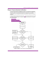
Phase II - Device Selection Verification .........................................................................................5-7
Phase III - Device Connection Verification ..................................................................................5-11
Phase IV - Output Verification .....................................................................................................5-17
Quick Reference - Vertigo XG Configuration Schemas....................................................................5-24
NTSC/PAL Configuration Settings - Fill Only, Input and Output ..................................................5-25
NTSC/PAL Configuration Settings - Fill and Key, Output Only....................................................5-26
HD 1080i30M Configuration Settings - Fill Only, Input and Output .............................................5-27
HD 1080i30M Configuration Settings - Fill and Key, Output Only ...............................................5-28
Dual Channel SD/HD Configuration Settings - Fill and Key, Input and Output............................5-29
Contact Us ............................................................................................................................ 6-1
Contact Miranda Technical Support ..............................................................................................6-1
Contact Miranda Technologies Inc. ...............................................................................................6-1
Index ............................................................................................................................... Index-1
TOC-2
Vertigo XG Configuration Guide
1 INTRODUCTION
The Vertigo XG is Miranda’s full-featured HD/SD graphics processor providing high
performance single or dual channel graphics rendering and video playback performance.
The Vertigo XG is ideal for a wide range of advanced real-time broadcast applications, like
HD/SD dual-casting with independent graphics for HD and SD, and single channel
applications demanding sophisticated, multi-channel branding and promotional graphics.
Figure 1-1. Miranda’s Vertigo XG Graphics Rendering System
The main purpose of this Configuration Guide is to provide practical reference and
procedural information on how to use the XG Dashboard application to configure the
Vertigo XG graphics processing system.
The following sections of this document provide information regarding the capabilities and
features of the Vertigo XG and its configuration software, XG Dashboard:
•
“About the Vertigo XG” on page 1-2
•
“Key Features” on page 1-4
•
“Licensing Information” on page 1-5
•
“Preliminary Guidelines and Recommendations” on page 1-7
•
“Vertigo XG Hardware” on page 2-1
•
“VertigoXG and Renderer Windows” on page 3-1
•
“XG Dashboard - Vertigo XG’s Configuration Software” on page 4-1
Vertigo XG configuration procedures are described in the following chapters of this
document:
•
“XG Dashboard - Vertigo XG’s Configuration Software” on page 4-1
•
“Vertigo XG Configuration Procedures and Schemas” on page 5-1
Vertigo XG Configuration Guide
1-1
Introduction
About the Vertigo XG
The Vertigo XG is a hardware-based graphics rendering system for producing real-time
HD/SD graphics for broadcast branding and productions.
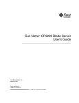
As illustrated in figure 1-2, the Vertigo XG is used in conjunction with Xmedia Suite v4.0
applications, which allows you to create and publish a wide range of graphics, including
advanced, data-driven broadcast applications that link on-air graphics elements to live data
feeds through simple drag-and-drop operations. The Xstudio application also allows you to
create “soft” control panels to control the broadcast. Each Vertigo XG includes one fixed
version of Xstudio-LT for template creation, and one fixed version of Xplay for playout
control. Note that dual channel Vertigo XG devices come with two copies of Xplay.
Figure 1-2. Sample architecture of Miranda’s Xmedia Suite v4.0
1-2
Vertigo XG Configuration Guide
Introduction
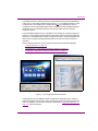
The Vertigo XG has two software interfaces, the VertigoXG window and the XG Dashboard,
to help you run and configure XG devices (see figure 1-3). The VertigoXG window is used
to load scenes to be outputted by the Vertigo XG device. The Vertigo XG can also be
configured to have the VertigoXG window open simultaneously with an additional window,
the Renderer (or Live Window), allowing you to preview loaded scenes on the host
computer’s monitor.
The XG Dashboard application is a new addition to the Vertigo XG. Through a single user
interface, you can perform hardware/software configuration and monitoring of one particular
XG device, or all available XGs currently running on the network. The XG Dashboard also
offers a series of pages containing the parameters that control how video and audio is
outputted.
See the following sections for more information about the XG Dashboard application:
•
“VertigoXG Window” on page 3-2
•
“XG Dashboard - Vertigo XG’s Configuration Software” on page 4-1
•
“Vertigo XG Configuration Procedures and Schemas” on page 5-1
VertigoXG & Renderer Windows
XG Dashboard
Figure 1-3. The Vertigo XG software interfaces
Vertigo XG devices are available in various configurations, depending on the number of
channels needed, the format of the output, and the storage options. Options also exist for
audio, clip playback, and external control (GPI 7 RS422). See “Vertigo XG Hardware” on
page 2-1 for more information.
Vertigo XG Configuration Guide
1-3
Introduction
Key Features
Some of the Vertigo XG’s key features include:
1-4
•
0, 1 or 2 Video input channels
•
2 or 4 Video output channels
•
SD and HD Video support
•
AES audio support: 8 in / 16 out AES/EBU audio total, 4 in / 8 out per output video
channel
•
16 embedded audio channels per SDI stream
•
Independent DVEs on each Video input
•
Tri-mode hardware Video bypasses
•
VAnc + VBI extraction, and processing
•
VAnc/VBI pass through
•
Integrated CG, Clip Player, Audio Player
•
Multi-format clip player, which supports most broadcast codecs
•
QuickTime and AVI with alpha channel playback
•
Centralized graphics creation, browsing, management, and distribution supported by
the Xmedia Server
•
Customizable run-time control panels with integrated Xpanel software
•
Optional Xstudio authoring tools for easy creation of scenes, graphics, templates, and
virtual control panels.
•
Unlimited virtual layers that can be controlled independently
•
Real-time control of live data sources with automatic on-air updates
•
True Type/Unicode character support
•
One seat of Xplay is included with each channel of the Vertigo XG purchased which
integrates the following features and functionality:
• Keyframe animation editor and timeline for real-time animation playback
• “As run” logging
• Automation interface via RS-232/422, GPI, TCP/IP, and Chyron Intelligent
Interface (III)
Vertigo XG Configuration Guide
Introduction
Licensing Information
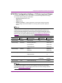
There are four (4) types of licenses available for the Vertigo XG to operate in its full capacity.
An additional license is available/required for the software CG. Each of the licenses is
described in the table below.
XGSD 4.0
The Vertigo XG requires an SD application license when outputting at SD
resolutions.
XGHD 4.0
The Vertigo XG requires an HD application license when outputting at HD
resolutions. An HD application license will also allow the XG to output at
SD resolutions.
XGAUDIO 4.0
The Vertigo XG requires a license to output certain types of audio. These
include: voice overs, clip audio, and AES discrete audio input/output. This
does NOT include embedded audio input/output.
XGCLIP 4.0
The Vertigo XG requires a license for clip playback.
XGSOFTWARE 4.0
The SoftwareCG requires a software application license to function
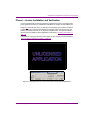
properly. If the SoftwareCG does not have a valid application license, then
the LiveWindow will show the message "Unlicensed Application" and the
SoftwareCG will be internally disabled. It will only accept Dashboard
connections at this point.
Instructions for verifying and installing licenses are available on page 5-3.
The Vertigo XG licenses are stored and managed by the Xmedia Server. Therefore, it is
important to specify the proper XMS connection settings on Dashboard’s Licensing page
(see page 4-27).
The Vertigo XG will not lose any functionality if they’re missing licenses. When the XG
detects that the user is trying to use a feature that is not licensed (ie: running the XG without
a proper application license, playing a clip without a clip license, or trying to use the AES
discrete audio without an audio license), it will enable a watermark feature.
Figure 1-4. A watermark message appears if the Vertigo XG is not properly licensed
Vertigo XG Configuration Guide
1-5
Introduction
The watermark appears on screen 2 hours after the initial license violation was detected.
The watermark only appears on screen for 5 seconds. The watermark will again appear 1
hour later and then every subsequent 30 minutes until a valid license is entered. 10 seconds
before showing any watermark, the XG will send a callback to the controlling application
(i.e. Xplay, Xstudio...) notifying it that the watermark is about to be shown on air. If the user
acknowledes the message, then Xplay will signal the XG not to show the watermark that
one time.
1-6
Vertigo XG Configuration Guide
Introduction
Preliminary Guidelines and Recommendations
Before you begin configuring and using the Vertigo XG, it is important that you read and
understand the guidelines and recommendations contained in the following sections.
Respecting these guidelines and recommendations will help to optimize the device’s
performance and help you to make more informed usage decisions.
•
“Vertigo XG Recommended Media Formats” on page 1-7
•
“Vertigo XG Virus Protection Guidelines” on page 1-10
•
“Publish Path Coordination Guidelines” on page 1-13
Vertigo XG Recommended Media Formats
The Vertigo XG is a fully software based clip/image/media reader, which allows for a
significant amount of flexibility with regards to media formats. However, to ensure optimal
generation and playback, the following topics make recommendations regarding which
media formats are preferred:
•
“Image Format” on page 1-7
•
“Cel Animation Format” on page 1-7
•
“Clip Format” on page 1-8
•
“Audio Format” on page 1-9
Image Format
As the Xmedia Suite handles static image file format conversions, the Vertigo XG supports
several image formats. However, for optimal results we recommend the following format:
Targa(.tga) 32bit uncompressed
Cel Animation Format
As the Xmedia Suite handles static image file format conversions, the Vertigo XG supports
several image formats. However, for optimal results we recommend the following format:
A sequence of Targa (.tga) 32bit uncompressed (i.e. bug_00001.tga to
bug_09999.tga)
Vertigo XG Configuration Guide
1-7
Introduction
Clip Format
Clip playout is only available with the Vx-ClipPlayer option (see “Clip Player” on page 2-10).
With this option, the Vertigo XG supports several Clip formats. For optimal results, it is
recommended to use the MPEG-2 (.MPG or .mpeg) media format. The Vertigo XG’s
decoders are optimized for MPEG-2, including HW acceleration, which results in significant
CPU savings. Since MPEG-2 does not typically support alpha channel, the Vertigo XG also
accepts Quicktime’s .MOV format. Although supported, .MOV files may have certain HD
playback limitations that can be avoided by using MPEG-2 instead.
NOTE
Windows Media Player 11 must be installed on the PC. However, QuickTime should not be
installed on the PC. Rather, QuickTime Alternative (version 1.81) should be installed. If
QuickTime is installed it will conflict with QuickTime Alternative and MainConcept’s MPEG2
player.
For HD clip encoding, it is highly recommended that MPEG-2 be used as the primary
encoding format.
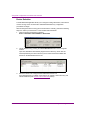
Video Format
NTSC
PAL
1080i30M
1080i25
Region
North America
Europe
North America
Europe
Resolution
720 x 480
720 x 576
1920 x 1080
1920 x 1080
Frame Rate
29.97
Drop Frame
25
Non-Drop
Frame
29.97
Drop Frame
25
Non-Drop
Frame
Data Rate
8 MBits
8 MBits
20 MBits
20 MBits
MPEG-2 Profile
4:2:2
4:2:2
4:2:2
4:2:2
MPEG-2 Level
High
High
High
Field Order
High
Interlaced,
2nd
Field Top
Interlaced,
1st
Field Top
De-interlaced, Progressive
Audio
1-8
•
•
•
SAMPLE TYPE:16-bit
SAMPLE RATE: 48 kHz
CHANNEL COUNT: 2 (stereo)
Vertigo XG Configuration Guide
Introduction
For QuickTime formats, it is recommended that you use the following H.264 settings:
Video
•
•
•
•
•
RESOLUTION: 1920 x 1080
FRAME RATE: 29.97, Drop Frame
DATA RATE: Constant Bit Rate, 20 MBits
PIXEL RATIO: Square
FIELD ORDER: Progressive (If the source is interlaced, be sure to
activate de-interlacing in XG Dashboard)
Audio
•
•
•
•
COMPRESSION: 24-bit Integer
SAMPLE TYPE:16-bit
SAMPLE RATE: 48 kHz
CHANNEL COUNT: 2 (stereo)
NOTE
Some issues may arise when using H.264 within the QuickTime wrapper. These issues can
be overcome by generating an MPEG-4 using H.264 encoding, instead of generating
QuickTime files using H.264 encoding. For more information, contact Miranda’s Technical
Support department.
NOTE
Due to an error in the current direct show MOV decoding Codecs, all .mov files must have
an accompanying audio track. This track can be empty though.
Audio Format
The Vertigo XG will pass embedded audio channels through with the video, while discrete
audio is only available through the addition of the Vx-Audio option (see“Audio Input/Output
Channels” on page 2-7). In addition, any audio processing (i.e. adding voiceovers, sounds,
audio ducks, etc.) also requires the Vx-Audio option. The Vertigo XG only supports the
Wave (.WAV) audio file format, and the audio file must have the following properties:
•
SAMPLE TYPE: 16 bit
•
SAMPLE RATE: 48 kHz
•
CHANNEL COUNT: 2 (stereo)
NOTE
MP3 audio files are not supported, as audio files must be 48 kHz.
Vertigo XG Configuration Guide
1-9
Introduction
Vertigo XG Virus Protection Guidelines
Proper network setup and anti-virus software are key components of any virus protection
strategy. As such, we highly recommend that you adhere to specific rules outlined in this
section to avoid adversely affecting your production equipment’s on-air performance. Our
virus protection strategy, therefore relies on anti-virus software protection combined with
the following:
•
Network Setup and Configuration – A best case scenario for configuring your network
for maximum protection against infection.
•
Scheduled Scanning – In the event that the setup described in “Network Setup and
Configuration” cannot be implemented, this section offers strategies for configuring
anti-virus software and scheduling scans at the optimum times.
•
Standard Anti-Virus Protection – Standard anti-virus practices for machines and
applications not directly used for putting material on-air.
•
Institution of Policies – Policies that all users must follow in order to avoid introducing
infected files into the system.
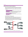
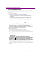
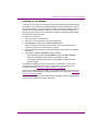
Network Setup and Configuration
Ideally, the Xmedia Server and other non-critical components should be running anti-virus
software, while the Vertigo XGs reside on a separate network. In such a case, the
Vertigo XGs would not be running anti-virus software, leaving them potentially vulnerable.
Therefore, provide proper protection and minimizing potential performance issues, it is
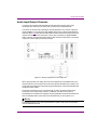
recommended that restricted access be available by means of switch (see figure 1-5). It is
also recommended that all other Xmedia equipment would be kept on a separate network
isolated from other machines in the facility.
Restricted
Internet
Switch
XStudio
Network
Figure 1-5. Recommended network configuration to provide virus protection
1-10
Vertigo XG Configuration Guide
Introduction
The only machine the Vertigo XG needs to access is the Xmedia Server on port 14050 and
the Data Server on port 14060. The playout machines need access to the Vertigo XG on
ports 4000, 15000, and the Vertigo XG usues port 4545 (UDP) and ports 5000 to 5010 for
Dashboard connections.
If isolating the Vertigo XGs is not possible try Scheduled Scanning.
Scheduled Scanning
If isolating the Vertigo XGs in the manner described the Network Setup and Configuration
section is not an option, the following measures constitute a good alternative.
While it is understood that following all guidelines may not be practical, they nevertheless
provide a high level of protection against system infection.
•
NEVER share a folder or drive with “Everyone” with full-access.
•
ALWAYS assign a local Administrator password to every machine. Failure to do so
poses a serious security threat.
•
Do not store files with .EXE extensions in directories with write permissions.
•
Disallow Internet access on all Vertigo Xmedia machines that do not require it.
•
Install and run anti-virus software on all PC components that are not used for on-air
play out.
Anti-virus software can potentially degrade the performance of on-air applications, resulting
in video or audio glitches in the on-air output. We therefore caution against the installation
of anti-virus software on any hardware components used on-air and recommends regularly
scheduled system scans. These should be performed during periods when the system is
not being used and the Vertigo XG is not running. Moreover, scans should occur daily.
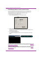
Virus scanning software should be installed on a separate machine that can be used as a
central management console (see figure 1-6). Your IT department should make sure that
the proper permissions and configurations are set up on each individual Vertigo XG to allow
for network scanning from the central console.
Anti-Virus Management Console
Figure 1-6. Install virus scanning software on a central management console
Vertigo XG Configuration Guide
1-11
Introduction
Most anti-virus applications allow for the exclusion of certain files from the virus scan. As
the Vertigo XG relies heavily on media files, there can be a large number of these files on
the system. To speed up scanning, these files can be excluded from the scans. Being nonexecutable files that cannot spread to other systems, they pose no risk for infection.
The list below specifies the file types that can be excluded through the anti-virus software.
•
Clip files: .AVI, .MPG, .DV, .MOV
•
Standard image files: .BMP, .G, .GF, .JPG, .PCD, .PCT, .PCX, .PIC, .TGA, .TIF, .TV
•
Standard audio files: .WAV
Standard Anti-Virus Protection
While critical for the on-air production process, many od Miranda’s Xmedia Suite products
do not put material directly on air. We therefore recommend that these products be
configured with the same high level of anti-virus protection used for other machines on the
broadcaster’s network.
The following Xmedia Suite products should be configured with the highest level of antivirus protection:
•
Xmedia Server
•
Data Server
•
Xstudio
•
Xbuilder
The following applications should also be configured with the highest level of anti-virus
protection, unless installed on the same machine as the Vertigo XG. In this case, refer to
the recommendations in “Network Setup and Configuration” on page 1-10.
•
Xplay
•
Xpanel
Institution of Policies
While the guidelines outlined in the previous sections are critical to your broadcast
network’s protection from infection, end users must accept some responsibility. We
therefore recommend that your IT department enforce the following policies:
1-12
•
Any machine that will be attached to the same network as the Vertigo XG must undergo
a complete system scan.
•
Any floppy, zip or other external media to be copied to or run on the Vertigo XG must
undergo a complete scan.
•
Material to be used in 24/7 operation should not be copied to the Vertigo XG. Instead,
it should be transferred only during maintenance periods.
•
Do not download Internet files directly onto the Vertigo XG.
Vertigo XG Configuration Guide
Introduction
Publish Path Coordination Guidelines
The Xmedia Suite moves media from the central store, the Xmedia Server, to the
Vertigo XG rendering device in a process referred to as publishing. A special service active
on the Vertigo XG, the Xpublish Agent (XPA), is responsible for receiving and processing
the publish requests and making the media available to the Vertigo XG. The XPA service’s
Base Path setting controls where media is stored on the recipient device, and this setting
must match where the Vertigo XG rendering engine is looking to find the media.
Therefore, the publish path directory setting must be identical in the Xpublish Agent and the
XG Dashboard. The default directory for Vertigo XG hardware devices is F:\Scene, on
both the Xpublish Agent and XG Dashboard. To ensure that assets are properly stored and
available to the Vertigo XG, It is recommended that you verify that these settings match.
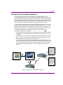
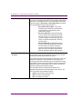
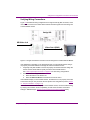
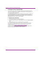
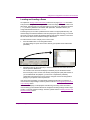
To emphasize the importance of matching the publish path settings, figure 1-7
demonstrates the logic of these settings:
1. Graphics that are created using an external graphics editor are ingested into Xstudio.
2. The graphics are stored on the Xmedia Server as assets and then used to build scenes
in Xstudio.
3. When the scenes are published, the Xmedia Server transfers the files to the Xpublish
Agent running on the Vertigo XG. The Xpublish Agent saves the files locally to the
directory path specified in its Base Path parameter (i.e. F:\scene).
4. When the Vertigo XG wants to load and render these scenes, it recalls the files from
the storage directory specified in the XG Dashboard’s Publish Path parameter, which
must be identical to the directory location where the Xpublish Agent saved to the files.
If not, then Dashboard will be looking in one directory, while the files are stored in
another.
1
External Graphics Editor
4
XG Dashboard
Xstudio
2
3
Xpublish Agent
Figure 1-7. Publish Path settings must be identical
Vertigo XG Configuration Guide
1-13
Introduction
Verify that the publish path directories are identical
1.
2.
1-14
Open the VertigoXmedia Xpublish Agent and verify/edit the Base Path parameter on
the Instance tab.
a. Open the VERTIGOXMEDIA XPUBLISH AGENT from the host computer’s Windows
Control Panel.
START>SETTINGS>CONTROL PANEL>VERTIGOXMEDIA XPUBLISH AGENT
b. Select the INSTANCES tab.
c. Verify that the directory location in the BASE PATH parameter is set to F:\Scene.
If it is, then click OK to exit.
If it is not, then type F:\Scene in the Base path parameter’s text box and click OK.
Open XG Dashboard and verify/edit the Publish Path parameter on the Device
Settings’ General page.
a. Open the XG Dashboard application (see “Starting the XG Dashboard” on page
4-3).
b. Select the XG hardware device from the Device List.
c. Select the Device Settings tab.
d. Verify that the directory location in the PUBLISH PATH parameter is set to
F:\Scene\. If it is, then there is no need to make changes.
If it is not, then type F:\Scene\ in the PUBLISH PATH parameter’s text box and
then click the APPLY CHANGES button.
Vertigo XG Configuration Guide
2 VERTIGO XG HARDWARE
The Vertigo XG is a broadcast graphics system for both rich branding and production
graphics. Physically, the Vertigo XG is a 3RU rackmount rendering platform that
incorporates redundant fans, power, and ethernet ports, with RAID-enable storage,
expandable up to 1.8 TB.
The following table demonstrates that the Vertigo XG is available in various configurations,
depending on the number of channels needed and the format of the output.
Model of Vertigo XG
I/O Support
Clip Playback
VX-VertigoXG-SD11
Single channel SD graphics engine
•
•
1 SDI input
1 SDI F + K output
•
SD Clips
VX-VertigoXG-SD22
•
•
2 SDI inputs
2 SDI F + K outputs
•
SD Clips
•
•
0 SDI inputs
2 SDI F + K output
•
SD Clips
•
•
1 HD-SDI input
1 HD-SDI F + K output
•
SD/HD Clips
•
•
•
•
1 HD-SDI input
1 SD-SDI input
1 HD-SDI F + K output
1 SD-SDI F + K output
•
SD/HD Clips
•
•
•
0 HD-SDI inputs
1 HD-SDI F + K output
1 SD-SDI F + K output
•
SD/HD Clips
Dual channel SD graphics engine
VX-VertigoXG-SD02
Dual F+K output SD graphics engine
(no input)
VX-VertigoXG-HD11
Single channel HD graphics engine
VX-VertigoXG-HD22
Dual channel HD + SD graphics engine
VX-VertigoXG-HD02
Dual F+K output HD + SD graphics engine
(no input)
Vertigo XG Configuration Guide
2-1
Vertigo XG Hardware
The following options are also available to enhance the performance and capabilities of the
Vertigo XG:
2-2
•
Additional RAID media storage (see “Media Storage” on page 2-9)
•
Discrete audio (see “Audio Input/Output Channels” on page 2-7)
•
Clip playback (see “Clip Player” on page 2-10)
•
EAS text and audio integration (see “Audio Input/Output Channels” on page 2-7)
•
PCI 8 Reed Relay Output/8 Isolated Input Module
•
BlueStorm/LP RS-422/485, Universal PCI
Vertigo XG Configuration Guide
Vertigo XG Hardware
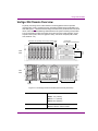
Vertigo XG Chassis Overview
Physically, the Vertigo XG is a 3RU rackmount rendering platform that incorporates
redundant fans, power, and ethernet ports, with RAID-enabled storage expandable up to
1800 GB. Figure 2-1 illustrates that the Vertigo XG features easy frontal access to the SCSI
drives, and a control panel featuring LEDs and buttons for system monitoring and operation.
The rear panel also provides convenient access to three power supply modules, six PCI
expansion slots (video, audio, and graphics cards), and various I/O ports (USB, COM1,
VGA, Ethernet...etc).
SCSI Drives for expanding media storage capacity Floppy
Drive
Control Panel
LEDs & Buttons CD-ROM Drive
Front
5.25”
Drive
Bays
Panel
Rear
Panel
Power
Supplies
I/O Ports
PCI Expansion Slots
Figure 2-1. The Vertigo XG device chassis (front and rear panel view)
Chassis
FORM: 3U rackmount chassis
HEIGHT: 5.2” (132mm)
WIDTH: 17.7” (450mm)
DEPTH: 25.5” (648mm)
Power consumption
Vertigo XG Configuration Guide
3 x 380W power supplies.
Maximum draw is a total of 760W.
2-3
Vertigo XG Hardware
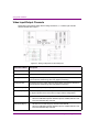
Figure 2-2 demonstrates that the control panel located on the front of the Vertigo XG
chassis has six LEDs and three buttons. The table following the figure 2-2 describes the
function of each LED and button, as well any corrective action you may need to take.
POWER
Power Overheat NIC2 NIC1
Fail Fan Fail
HDD
Power
Buttons
Figure 2-2. Vertigo XG chassis control panel LEDs and buttons
POWER FAIL
Indicates a power supply module has failed. This should be accompanied
by an audible alarm. A backup power supply module will take the load and
keep the system running, but the failed module will need to be replaced.
This LED should be off when the system is operating normally.
OVERHEAT / FAN FAIL
When this flashes, it indicates a fan failure. When it is constantly
illuminated (solid on), it indicates an overheat condition, which may be
caused by cables obstructing the airflow in the system or the ambient room
temperature being too warm. Check the routing of cables and make sure
that all fans are present and operating normally. You should also check to
make sure that the chassis covers are installed properly. Finally, verify that
the heatsinks are installed properly. This LED will remain flashing or on as
long as the above mentioned conditions exist.
NIC2
A flashing NIC2 LED indicates network activity on LAN2.
NIC1
A flashing NIC1 LED indicates network activity on LAN2.
HDD
Indicates IDE channel activity.
POWER (LED)
Indicates that power is being supplied to the system’s power supply units.
This LED should normally be illuminated when the system is in operation.
MUTE
Press the Mute button to silence the buzzer alarm, which is activated by a
signal received from the SCSI drive backplane. After silencing the alarm,
you should then press the button again to reactivate the alarm function.
RESET
The Reset button reboots the system.
POWER (BUTTON)
This is the main power button, which is used to apply or turn off the main
system power. Turning off this button removes the main power, but keeps
standby power supplied to the system.
2-4
Vertigo XG Configuration Guide
Vertigo XG Hardware
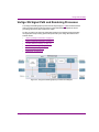
Vertigo XG Signal Path and Rendering Processes
The Vertigo XG HD/SD graphics processor block diagram (figure 2-3) demonstrates that the
audio and video signals are brought into the Vertigo XG hardware, exposed to various
processing options, and then rendered for output.
To help you make more informed configuration decisions, the following sections describe
the signal path and processing options that performed by the Vertigo XG hardware and
software drivers.
•
“Video Input/Output Channels” on page 2-6
•
“Audio Input/Output Channels” on page 2-7
•
“Ancillary Data Processing” on page 2-8
•
“Graphics Processing” on page 2-8
•
“Media Storage” on page 2-9
•
“Clip Player” on page 2-10
Figure 2-3. Vertigo XG HD/SD graphics processor block diagram
Vertigo XG Configuration Guide
2-5
Vertigo XG Hardware
Video Input/Output Channels
Depending on the model of Vertigo XG, the Vertigo XG offers 0, 1, or 2 video input channels
with SD and HD video support.
Figure 2-4. Wiring configuration for the Vertigo XG
Pin/Channel Name
Description
SDI In A
SDI IN A is the primary input channel connection.
SDI In B
SDI IN B can act as a separate Fill channel.
Analog Ref In
Analog Ref In is the input reference signal used by the Genlock hardware to
synchronize the phase timing video and graphics processing.
Analog Ref Out
Analog Ref Out is the output reference signal used by the Genlock hardware to
synchronize the phase timing video and graphics processing.
SDI OUT A (Fill 1)
SDI OUT A (Fill 1) is the primary output channel connection.
SDI Out B (Fill 2)
SDI OUT B (Fill 2) is the second output channel in a dual-channel configuration.
No signal is present at this connection for single-channel configurations.
SDI Out C (Key 1)
•
•
SDI OUT C is the matching Key channel for SDI OUT A.
When the OnBoardCompositor firmware option is installed, SDI OUT C &
D become dedicated Key channels.
SDI Out D (Key 2)
•
•
SDI OUT D is the matching Key channel for SDI OUT B.
When the OnBoardCompositor firmware option is installed, SDI OUT C &
D become dedicated Key channels.
2-6
Vertigo XG Configuration Guide
Vertigo XG Hardware
Audio Input/Output Channels
The Vertigo XG supports both embedded and discrete audio channels. Each video
input/output can contain up to 8 stereo pairs (16 channels) of embedded audio.
The number of discrete audio input/output channels depends on the number of physical
inputs available. For each physical input available there will be a discrete audio breakout
cable (see figure 2-5). Each discrete audio breakout cable contains 2 XLR inputs and 4 XLR
outputs. Each XLR connector represents 1 stereo pair (2 channels) of digital AES/EBU
audio. Therefore, each discrete audio breakout cable contains 2 stereo pairs (4 channels)
of input and 4 stereo pairs (8 channels) of output.
Figure 2-5. Wiring configuration for the Vertigo XG
When capturing audio, the Vertigo XG must choose between the embedded audio or the
discrete audio as a source. Both sources cannot be captured simultaneously. However, the
Vertigo XG can broadcast the same audio signal simultaneously on both the embedded and
the discrete audio outputs.
The Vertigo XG performs one-to-one passthrough of audio. All captured audio will be
broadcast on the corresponding outputs. For example, if the first 2 stereo pairs of
embedded audio on SDI IN A are captured, then the signal will be output as the first 2 stereo
pairs of embedded audio on SDI OUT A and simultaneously on XLR outputs 1 & 2.
NOTE
The hardware bypass, in the case of power failure or system crash, does not include the
discrete AES/EBU channels.
Vertigo XG Configuration Guide
2-7
Vertigo XG Hardware
Ancillary Data Processing
The Vertigo XG reserves some hardware functionality for the extraction, processing, and
insertion of ancillary data into the output video signal, for example, Vertical Ancillary (VAnc)
data and Vertical Blanking Interval (VBI) data.
The ancillary data space can be used as a transport mechanism for data to be extracted by
the Vertigo XG for triggering keyers, squeezes (DVEs) or other graphics events. Metadata
embedded upstream of the Vertigo XG is extracted and processed by the control application
to control these actions.
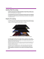
Graphics Processing
The Vertigo XG is a multi-layered graphics engine that supports loading of multiple graphics
scenes on independently-controlled, dynamic layers. The number of layers to be controlled
is defined in the control application (Xplay, Xplay Pro, or Xpanel).
Figure 2-6. The Vertigo XG supports the production of multi-layered graphics
The engine supports a large number of graphics objects, including input video, images,
clips, cel animations, text, crawls, rolls, all within a single graphics layer. Graphics output is
created by positioning objects within a graphics scene using the authoring tool set, and
loading the scene onto the Vertigo XG.
Digital video effects (DVEs) are created, loaded, and controlled as standard graphics. The
video object supports a wide variety of integrated transitions, as well as a full animation
timeline to create custom moves.
The Vertigo XG can be configured for fill + key SDI video outputs, where the keying of
graphics over video is handled externally, or can composite together the final output
internally, outputting the complete signal. The Vertigo XG also supports hardware and
software bypasses for video inputs in the case of power loss and hardware or software
failure.
2-8
Vertigo XG Configuration Guide
Vertigo XG Hardware
Media Storage
The Vertigo XG’s chassis has seven SCSI drive bays that can be fitted with additional drives
to expand the device’s storage capacity. Two types of hardware (RAID-1 and RAID-5) are
used for onboard storage of media like clips, images, and animations.
The table below demonstrates that some Vertigo XG offers versatile storage options using
RAID-1 drives to provide up to 146 GB or 300 GB of storage, as well as using RAID-5 drives
in the chassis’ expandable drive slots to extend the Vertigo XG’s storage capacity from
146 GB to 1.8 TB.
Product code
Description
Number of drives
VX-146-L1
146 GB RAID-1 storage
2 x 146 GB
VX-300-L1
300 GB RAID-1 storage
2 x 300 GB
VX-146-L5-XG
146 GB RAID-5 storage
3 x 73 GB
VX-300-L5-XG
300 GB RAID-5 storage
3 x 146 GB
VX-600-L5-XG
600 GB RAID-5 storage
3 x 300 GB
VX-600P-L5-XG
600 GB RAID-5 storage
5 x 146 GB
VX-900-L5-XG
900 GB RAID-5 storage
4 x 300 GB
VX-1200-L5-XG
1.2 TB RAID-5 storage
5 x 300 GB
VX-1500-L5-XG
1.5 TB RAID-5 storage
6 x 300 GB
VX-1800-L5-XG
1.8 TB RAID-5 storage
7 x 300 GB
NOTE
When upgrading storage capacity, you cannot mix disk sizes within the same Vertigo XG
device. In other words, a device that has 146 GB drives can only upgrade using additional
146 GB drives, not 300 GB drives.
Vertigo XG Configuration Guide
2-9
Vertigo XG Hardware
Clip Player
The Vertigo XG offers a video/audio clip player option that can output clips simultaneously.
It is ideal for the playout of full screen or partial screen clips, and the player supports
MPEG2 broadcast codecs.
The table below demonstrates that when the clip player is used with the expandable RAID
storage options, the Vertigo XG allows for the storage of up to 600 hours of clips in multiple
formats.
Clip storage with different storage options (hours)
Mbps
146 GB
300 GB
600 GB
900 GB
1200 GB
1500 GB
1800 GB
10
30
60
120
180
240
300
360
35
8
16
32
48
64
80
96
50
6
12
24
36
48
60
72
100
3
6
12
18
24
30
36
Also see “Vertigo XG Recommended Media Formats” on page 1-7 for recommendations
regarding which media formats will ensure optimal generation and playback.
2-10
Vertigo XG Configuration Guide
3 VERTIGOXG AND RENDERER WINDOWS
The main function of the VertigoXG window is to allow you to load scenes to be outputted
by the Vertigo XG device. The Vertigo XG can also be configured to have the VertigoXG
window open simultaneously with an additional window, the Renderer, allowing you to
preview the loaded scene on the host computer’s monitor.
Figure 3-1. VertigoXG window
The following sections provide you with an overview of these interfaces and usage
information that is relevant to configuring the Vertigo XG:
•
“VertigoXG Window” on page 3-2
•
“XG Renderer Window” on page 3-3
Vertigo XG Configuration Guide
3-1
VertigoXG and Renderer Windows
VertigoXG Window
The VertigoXG window is simple user interface that allows you to perform basic tasks for
operating the Vertigo XG like, loading a scene and launching the XG Dashboard
application. By default, the window will automatically open when the XG hardware is
started, otherwise you can launch the window using the desktop shortcut.
NOTE
The software CG application’s user interface has the same look and functionality as the VertigoXG
window. You can launch the software CG’s window using the desktopn shortcut, or by selecting
VERTIGOXMEDIA>VERTIGOXMEDIA SOFTWARE CG from the Windows START>PROGRAMS menu.
The following tables provides descriptions for each of the buttons and fields on the VertigoXG
window:
LOAD button
Launches the OPEN dialog box, so that you can select and load a scene to
the Vertigo XG. The directory that the Open dialog box opens to is set in the
Publish Path parameter on the General page. The default directory location
for Vertigo XG scenes is F:\Scene. Please see “Publish Path
Coordination Guidelines” on page 1-13 for instructions about how to
properly set the publish path directories.
If the Live Window is enabled on the Dashboard’s Live Window page, the
scene will be displayed immediately in the Renderer window when loaded.
DISCONNECT
Promptly closes the connection between the XG/CG device and the
application that it was actively connected to.
EXIT button
Closes the VertigoXG window.
LAUNCH DASHBOARD
button
Opens the XG Dashboard, which is an application that allows you to
configure the settings and behavior of Vertigo XG hardware devices (see
“XG Dashboard - Vertigo XG’s Configuration Software” on page 4-1).
LOCAL HOST
These read-only fields display information regarding the local host
computer that is being used to run/control the Vertigo XG devices.
NAME: Name of the host computer.
IP: The IP address of the host computer.
PORT: The port number that is dedicated to the Vertigo XG
3-2
Vertigo XG Configuration Guide
VertigoXG and Renderer Windows
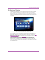
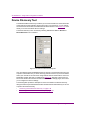
XG Renderer Window
In addition to the output display, you can configure the Vertigo XG to preview the loaded
scene in the Renderer window on the host computer’s monitor. This is functionality is
particularly useful when you would like to preview the on-air contents when performing
diagnostics and debugging tasks. Note that the Renderer window is also referred to as the
Live Window.
Figure 3-2. The XG Renderer window (Live Window)
You can activate, or remove, the XG Renderer window using the XG Dashboard’s Live
Window page’s parameters. The Live Window page also allows you to configure the
appearance, size, and positioning of the window on the host computer’s monitor (see “Live
Window Page” on page 4-18).
Using the Dashboard’s Device Settings’ General Page you can also configure the
Vertigo XG to display some of the device’s operating information (statistics) on the
Renderer display. The statistics that can be displayed are: the frame rate, video card,
memory use, and timing information (Dx9, DSX, Readback). These statistics can be useful
for debugging purposes.
Vertigo XG Configuration Guide
3-3
VertigoXG and Renderer Windows
3-4
Vertigo XG Configuration Guide
4 XG DASHBOARD - VERTIGO XG’S
CONFIGURATION SOFTWARE
The XG Dashboard is an application that allows you to modify the settings and behavior of
Vertigo XG hardware devices and Vertigo software CG devices. This application can target
one particular XG/CG or all available XG/CGs currently running on the network. The XG
Dashboard application simplifies the Vertigo XG configuration process by offering a series
of pages containing the parameters that control how video and audio is rendered and
output.
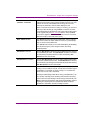
Figure 4-1. The XG Dashboard Window
The following topics further explain the function of the XG Dashboard, as well as orient you
to the various parts of the XG Dashboard’s interface:
•
“About XG Dashboard” on page 4-2
•
“XG Dashboard Window Components” on page 4-4
See “Vertigo XG Configuration Procedures and Schemas” on page 5-1 for usage
information.
Vertigo XG Configuration Guide
4-1
XG Dashboard - Vertigo XG’s Configuration Software
About XG Dashboard
The XG Dashboard is an application that allows you to modify the settings and behavior of
Vertigo XG and Vertigo software CG devices. The Vertigo XG is a hardware unit that
performs broadcast quality graphics rendering and playback, while the Vertigo software CG
is a software-based utility for rendering and previewing broadcast graphics.
One of the first things that XG Dashboard does is perform a device discovery, which
searches your local machine and/or your network for all active Vertigo XG/CG devices and
then lists them on Dashboard’s Device List. Using the Device Discovery Tool, Dashboard
allows you to configure the device discovery’s search parameters resulting in a more
focused search for a particular device, or a broader search to reveal more devices. See
“Device Discovery Tool” on page 4-36 for more details.
Once the devices are listed and active in the device table, you can select a device from the
list, which activates a series of device configuration tabs and pages in the lower portion of
the Dashboard interface.
The General Information Tab is the first to be displayed and creates a read-only profile
about the selected device and its system, which can be useful information when
troubleshooting.
The Device Settings Tab and Pages provide access to a series of eight (8) pages that
display the parameters and settings for the selected device. One thing to note is that the
seventh page is dynamic, meaning that when the selected device is a hardware XG the
seventh page is entitled “Hardware Settings”, but when the selected device is a software
CG the seventh page is entitled “AV Input”.
A description of each page and their parameters/settings is provided in “Device Settings Tab
and Pages” on page 4-12. The descriptions generally state what the parameter is and
informs you of what should be taken into consideration when changing the default settings.
By selecting the various pages, you can edit the device’s settings to build your desired
configuration, and then apply the changes to the device (see “Device Settings Tab Buttons”
on page 4-13).
Consult the following sections of this document for further details and instructions on using
the XG Dashboard application to configure and monitor Vertigo XG devices:
4-2
•
“Starting the XG Dashboard” on page 4-3
•
“XG Dashboard Window Components” on page 4-4
•
“Getting Started - Preliminary Configuration Procedures” on page 5-2
•
“Quick Reference - Vertigo XG Configuration Schemas” on page 5-24
Vertigo XG Configuration Guide
XG Dashboard - Vertigo XG’s Configuration Software
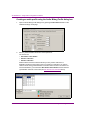
Starting the XG Dashboard
The XG Dashboard application can be started by clicking the LAUNCH DASHBOARD button
on the Vertigo Hardware XG window.
Figure 4-2. Click the LAUNCH DASHBOARD button to start the XG Dashboard
Alternatively, the XG Dashboard application can also be started independently by:
• opening the Dashboard.exe file stored in the following directory on the
host computer: C:\Program Files\VertigoXmedia\Apps\VertigoCG2
Or,
• clicking the Vertigo XG task bar icon
and select the LAUNCH DASHBOARD
command.
Vertigo XG Configuration Guide
4-3
XG Dashboard - Vertigo XG’s Configuration Software
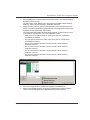
XG Dashboard Window Components
The XG Dashboard is a graphical interface that consists of a series of pages containing the
parameters and settings for the Vertigo XG and software CG devices found on your local
machine and/or on the network.
Figure 4-3 and the following sections describe the various components that make up the
XG Dashboard’s interface:
•
“XG Dashboard Menus and Buttons” on page 4-5
•
“Device List” on page 4-7
•
“General Information Tab” on page 4-10
•
“Device Settings Tab and Pages” on page 4-12
•
“Device Discovery Tool” on page 4-36
•
“Audio Mixing Profiles Dialog Box” on page 4-39
Menus
Buttons
Device List
Tabs
Pages
Figure 4-3. XG Dashboard window components
4-4
Vertigo XG Configuration Guide
XG Dashboard - Vertigo XG’s Configuration Software
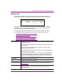
XG Dashboard Menus and Buttons
The following tables describe the XG Dashboard menu commands and the actions that they
perform:
•
File Menu
•
Device Menu
•
Tools Menu
•
Help Menu
File Menu
LOAD DEVICE LIST
Clears the Device List and repopulates it using the saved list of devices
stored on disk from a previous session.
When XG Dashboard starts up, it automatically performs a load to populate
the device list. If the saved device list is empty, Dashboard performs a scan
to detect any new devices. Note that this is the same type of scan action as
clicking the refresh button.
SAVE DEVICE LIST
Saves all the devices already in the Device List to a file on the disk, so that
Dashboard avoids having to detect devices every time it is run. See also the
EXIT command and “SAVE DEVICE LIST ON EXIT” on page 4-37.
EXIT
Closes the XG Dashboard application.
The first time you exit Dashboard, the AUTO-SAVE ON EXIT dialog box
appears before the application closes and asks you if you want to
automatically save the device list. Click YES to save the device list and close
Dashboard, or NO to simply close XG Dashboard.
During subsequent exits the Auto-Save on Exit dialog box will not appear. If
you would like to save the device list, however, you can use the File menu’s
“SAVE DEVICE LIST” command, or select “SAVE LIST ON EXIT” on the Device
Discovery Tool.
Vertigo XG Configuration Guide
4-5
XG Dashboard - Vertigo XG’s Configuration Software
Device Menu
REFRESH DEVICE LIST
Updates the Device List by launching a search for available Vertigo XG and
software CG devices using the Device Discovery settings specified in the
Device Discovery Tool dialog box.
RESTART DEVICE
Restarts the Vertigo XG or software CG device that is selected in the Device
List. The device may need to be restarted to have certain settings take effect
when you are configuring the device. When these settings are changed,
Dashboard automatically prompts you with a dialog box asking if you want to
restart the device immediately when the settings are changed. If you would
rather restart the device at a later time, refuse Dashboard’s request and use
the Restart Device command later when you are ready to restart the device.
MONITOR DEVICE STATUS
When selected, it will poll all the devices in the Device List to see if the status
has changed. For example, active devices have become inactive, or inactive
devices have become active.
Note that the interval between polling can be changed using the REFRESH
RATE parameter on Device Discovery Tool.
Tools Menu
SETTINGS > DEVICE
DISCOVERY
Opens the Device Discovery Tool, which is used to set the method that will
be used to detect available devices, whether they are local or remote (on the
network).
Help Menu
Opens the About XG Dashboard dialog box, which displays the XG Dashboard product
information, including the version number.
4-6
Vertigo XG Configuration Guide
XG Dashboard - Vertigo XG’s Configuration Software
Device List
The Device List identifies the Vertigo XG and software CG devices that were found on the
host machine (local) and/or on the network when a device discovery search is performed.
Selecting the device’s row from the list activates a series of device configuration tabs/pages
in the lower portion of the XG Dashboard interface. It is within these pages that you can
configure the device by editing its parameter settings.
The following table provides a description for each of the fields in the Device List and the
topics listed below describe the tasks that you can perform regarding the device table.
•
•
•
•
•
“Loading and refreshing the device list” on page 4-8
“Saving the device list” on page 4-8
“Restarting a device in the device list” on page 4-9
“Monitoring the status of a device” on page 4-9
“Removing a device from the device list” on page 4-9
OUTPUT CHANNEL
Displays the name of the output channel for the Vertigo XG hardware device.
Typically, this is A or B.
If the device is a Vertigo software CG , this field always displays “SWCG” as the
output channel.
A green or red light is displayed next to the output channel name, which
indicates the state of the device.
The green light indicates that the device is active, connected to XG Dashboard,
and ready to accept commands.
The red light indicates that the device is not active and no connection has been
established by XG Dashboard. Therefore, you need to start the device and
connect it to XG Dashboard through the host computer or the network. See
“Press the APPLY CHANGES button.” on page 5-22.
HOST NAME
Displays the name of the host computer.
IP
Displays the IP address of the device.
OUTPUT RESOLUTION
Displays the setting of the output rendering resolution as specified on the
Resolution Page.
DESCRIPTION
Displays whether the device is a Software CG (Software-based rendering and
preview application) or a hardware XG (hardware-based renderer and
production device).
Vertigo XG Configuration Guide
4-7
XG Dashboard - Vertigo XG’s Configuration Software
Loading and refreshing the device list
The mechanism used to find and list devices on to the Dashboard Device List is a tool called
the Device Discovery Tool. As described on page page 4-36, the Device Discovery tool
allows you to select between two methods of searching for Vertigo XG/CG devices:
automatic or manual.
Upon starting, Dashboard automatically begins a device discovery to locate the available
Vertigo XG/CG devices and then lists them on the Dashboard’s Device List.
You can set the method used during the device discovery anytime, by accessing the Device
Discovery tool from the TOOLS > SETTINGS menu.
Use the Device menu’s REFRESH DEVICE LIST command, or the REFRESH button
, to
update the device list at anytime. This action starts a device discovery that scans the local
machine and/or network and updates the status of the devices already listed and adds any
newly found devices.
Devices that are actively connected and ready to be used with Dashboard are indicated in
the Device List with a green light next to their name, while inactive devices have a red light.
When a device discovery is performed and the list is refreshed, the status of the listed
devices is also updated. An inactive device means that it is not in communication with
Dashboard, perhaps because the device is turned off, it has crashed, or the network is
down. If the device has crashed, you can restart it using Dashboard’s RESTART DEVICE
command (see “Restarting a device in the device list” on page 4-9). When the device is
active again, performing a refresh of the device list will return its status to a green light.
Saving the device list
Upon starting, Dashboard automatically begins a device discovery to locate the available
Vertigo XG/CG devices and then lists them on the Dashboard’s Device List. This initial
device list can be saved, so that the next time Dashboard performs a device discovery
(refresh), it only has to update the status of the listed devices rather than searching for them
again.
Use the File menu’s SAVE DEVICE LIST command, or the SAVE button, to save the device
list. If you do not save the device list before exiting Dashboard, the application asks you if
you would like to save the device list before exiting. This prompt only happens the first time
you exit Dashboard after installation.
As an alternative to manually saving the device list, you can use the Device Discovery tool’s
AUTO-SAVE DEVICE LIST ON EXIT parameter to automatically save the device list when you
exit the Dashboard application.
4-8
Vertigo XG Configuration Guide
XG Dashboard - Vertigo XG’s Configuration Software
Restarting a device in the device list
During configuration, there are some device parameters that require that the Vertigo XG be
restarted before the new settings can take effect. When these settings are changed,
Dashboard automatically prompts you with a dialog box asking if you want to restart the
device immediately. If you would rather restart the device at a later time, decline
Dashboard’s request and use the Device menu’s RESTART DEVICE command when you are
ready to restart the device.
Another use for the Restart Device command is to re-activate a device from the Device List
that has become inactive (red light) because the device crashed. The RESTART DEVICE
command performs a remote restart of the device, which may resolve the issue and return
the device to an active state (green light) after performing a refresh of the device list.
Monitoring the status of a device
The status of a Vertigo XG device is reported in the Device List by a green (active) or red
(inactive) light next to its name. You can monitor the status of a device by activating the
Device menu’s MONITOR DEVICE STATUS command, which uses the REFRESH RATE setting
on the Device Discovery tool to determine at what frequency to update the device’s status
on the device list.
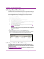
To monitor the status of a Vertigo XG device listed in the Dashboard Device List:
1. Select the device in the Device List.
2. Launch the Device Discover tool by selecting TOOLS > SETTINGS > DEVICE DISCOVERY.
3. Set the Device Monitoring’s Refresh Rate parameter to the desired frequency interval.
For example, a setting of 10, checks the status every 10 seconds.
4. Click OK.
5. Select the MONITOR DEVICE STATUS command in the DEVICE menu.
Removing a device from the device list
If the device list has previously been saved, it will list all of the Vertigo XG/CG devices found
and updated from the previous device discovery, including Vertigo XG/CG devices that are
active, inactive, local, and/or networked.
There may be times when you want to limit the devices displayed in the device list to a
particular few. If this is the case, you can tailor the device list by removing any unwanted
devices from the device list.
To remove a device from the device list:
1. Right-click on the device in the device list that you want to remove.
2. Select the REMOVE DEVICE command.
Vertigo XG Configuration Guide
4-9
XG Dashboard - Vertigo XG’s Configuration Software
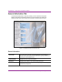
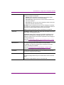
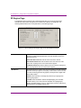
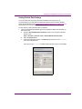
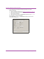
General Information Tab
The General Information tab is a read-only summary of some of the device and system
settings of the Vertigo XG selected in the Device List. Its main function is to gather and
display information that may be relevant when operating or troubleshooting the system.
Figure 4-4. Dashboard’s General Information Tab
General Information
DEVICE NAME
The name given by the last connecting application. Such as Xplay or
Xstudio. This should correspond to the name that is typically the XMS name.
Currently, the name defaults to XG.
COMPUTER NAME
Displays the name of the host computer.
IP ADDRESS
Displays the IP address of the selected Vertigo XG device.
DESCRIPTION
Displays whether the device is a Software CG (Vertigo Software CG) or a
hardware XG (Vertigo XG).
4-10
Vertigo XG Configuration Guide
XG Dashboard - Vertigo XG’s Configuration Software
Version Information
APPLICATION VERSION
Displays the version of XG/CG device.
DSX.UTILS VERSION
Displays the version of the driver used inside the Vertigo XG device.
(Hardware XG only)
Port Information
APPLICATION PORT
Displays the communication port used between the XG Dashboard
application and the selected Vertigo XG/CG device.
COMMAND PORT
The communications port used by the Vertigo XG/CG for command and
control by applications, such as Xstudio or Xplay. To edit this setting, select
the Display Settings Tab and edit the COMMAND PORT field.
Resolution Information
RENDERING
Displays the resolution format that is used for processing within the
Vertigo XG/CG.
To edit this setting, select the Resolution Page from the Device Settings tab
and edit the RENDERING RESOLUTION parameter.
INPUT
Displays the resolution format of the video data coming into the Vertigo XG.
This field does not apply to VertigoCG devices.
To edit this setting, select the Resolution Page from the Device Settings tab
and edit the INPUT RESOLUTION field.
OUTPUT
Displays the resolution format of the video data being outputted from the
Vertigo XG/CG. This field does not apply to Vertigo Software CG devices.
To edit this setting, select the Resolution Page from the Device Settings tab
and edit the OUTPUT RESOLUTION field.
Graphics
GRAPHICS CARD
Identifies the type of graphics card used by the Vertigo XG hardware or the
Vertigo Software CG. This information is useful when troubleshooting the
Vertigo XG as some functionality might depend upon the type of graphics
card used.
TOTAL MEMORY USE
Displays the total amount of memory being used by the graphics card,
including host and onboard.
Vertigo XG Configuration Guide
4-11
XG Dashboard - Vertigo XG’s Configuration Software
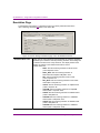
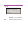
Device Settings Tab and Pages
Selecting the Device Settings tab provides access to a series of eight (8) pages that display
the parameters and settings for the selected device. Note that the seventh page is dynamic,
meaning that when the selected device is a hardware XG the seventh page is entitled
“Hardware Settings”, but when the selected device is a software CG the seventh page is
entitled “AV Input”.
Figure 4-5. Selecting the Device Settings tab exposes its pages
The following topics describes each of the settings on the Device Settings tab and its pages:
4-12
•
“Device Settings Tab Buttons” on page 4-13
•
“General Page” on page 4-14
•
“Resolution Page” on page 4-16
•
“Live Window Page” on page 4-18
•
“Clips Page” on page 4-20
•
“3D Engine Page” on page 4-22
•
“Logging Page” on page 4-24
•
“AV Input Page” on page 4-26
•
“Licensing Page” on page 4-27
•
“Genlock Page” on page 4-28
•
“Video Page” on page 4-31
•
“Audio Page” on page 4-33
•
“Watch Dog Page” on page 4-35
Vertigo XG Configuration Guide
XG Dashboard - Vertigo XG’s Configuration Software
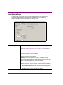
Device Settings Tab Buttons
By selecting the various pages, you can edit the settings to build your desired configuration,
and then apply the changes to the device. Note that for some changes to take effect,
Dashboard will request that the device be restarted (see “RESTART DEVICE” on page 4-6).
Device Settings
Buttons
Figure 4-6. Device Settings tab’s buttons
You can retract the changes that you make to the device settings by performing an UNDO,
as long as you haven’t already applied the changes. If you have made unwanted changes,
you can revert to the device’s default settings by pressing the RESTORE FACTORY DEFAULTS
button. These actions are performed by using the following buttons located in the lower
portion of the XG Dashboard window when the Device Settings tab is selected.
RESTORE FACTORY
DEFAULTS
Resets all of the parameter settings to XG Dashboard default settings.
APPLY CHANGES
Applies all of the new settings from the page to the selected device.
UNDO CHANGES
Reinstates the page’s device settings back to what they were at the last
“Apply Changes” action.
Vertigo XG Configuration Guide
4-13
XG Dashboard - Vertigo XG’s Configuration Software
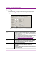
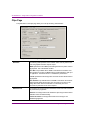
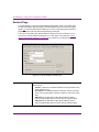
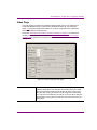
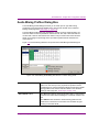
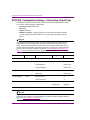
General Page
The General page (figure 4-7) provides you with access to a series of miscellaneous device
parameters, including storage settings and communication settings between the
Vertigo XG/CG, Xplay, and/or the broadcast monitor.
Figure 4-7. Device Settings’s General Page on the XG Dashboard Window
ASSETS
PUBLISH PATH: Identifies the directory location where assets are stored on
the Vertigo XG, or on the host computer (software CG). The default directory
paths for the Vertigo XG is F\:Scene\, while the default directory path for
the Vertigo Software CG is C\:Scene\.
Assets are automatically placed within appropriate subfolders by the publish
agent. For example, images are stored in the Image subfolder.
Please see “Publish Path Coordination Guidelines” on page 1-13 for
instructions about how to properly set the publish path directories.
TCP/IP
COMMAND PORTS: Sets the communications port used by the Vertigo XG
and Vertigo software CG for command and control between applications
(i.e. Vertigo XG/CG and Xplay). This port must be open and 2-way
unblocked on the Vertigo XG subnet.
CEL ANIMATIONS
CACHE SIZE: Sets the number of cel animations that are cached in system
memory after they are no longer referenced by a loaded scene.
The default is 5.
Increasing the cache size setting will unnecessarily slow down performance
and occupy memory space.
4-14
Vertigo XG Configuration Guide
XG Dashboard - Vertigo XG’s Configuration Software
AUTOMATION
MODE: Determines the timestamping mechanism used for commands
between the Vertigo XG and Xplay.
•
DISABLED: When selected the timestamp of the command will be
ignored and the command is executed immediately.
•
SYSTEM COUNTER: High performance counter issued to reference the
time of the command.
•
SYSTEM CLOCK: Sets the format of the timestamps, which is timecodebased (Hour: Minute: Seconds: Frames).
DEAD BAND: Sets the dead band zone for the time stamping of commands.
If the difference in timestamps between multiple commands is less than the
dead band, the earlier timestamp will be use for all commands.
PREROLL: Sets the preroll time by which all timestamps are adjusted.
STATISTICS
SHOW BASIC: Displays the frame rate, video card, and memory use on the
output display for debugging purposes.
SHOW EXTRA: Displays timing information (Dx9, DSX, Readback) on the
Vertigo XG’s output display for debugging purposes. Timing values are
displayed in milliseconds for each thread. This parameter does not apply to
the Vertigo Software CG.
Please see “Enable/Display Statistics on the broadcast monitor” on page
5-12 for instructions on displaying statistics.
DEVICE OUTPUT
FILL: Only the fill signal will be transmitted to the output monitor.
FILL AND KEY: The fill and key signals will be transmitted to the output
monitor. This setting is the default.
Please see “Verifying the Device Output Settings” on page 5-16 for
instructions on setting the Fill or Fill & Key settings.
PASSWORD
A simple security feature that allows you to set a password so that other
users cannot change the device settings.
INITIAL KEYER STATE
Sets the initial state of the Vertigo XG/CG internal virtual keyer list.
ON: Sets the Vertigo XG/CG’s keyer to an active state. This is the default
setting.
OFF: Sets the Vertigo XG/CG’s keyer to an inactive state.
Vertigo XG Configuration Guide
4-15
XG Dashboard - Vertigo XG’s Configuration Software
Resolution Page
The Resolution page (figure 4-8) provides access to the device parameters that set the
input, rendering, and output resolution of the video data.
Figure 4-8. Device Settings’s Resolution page on the XG Dashboard window
RENDERING RESOLUTION
4-16
Based upon the output resolution format selected, the rendering resolution
field allows you to select the internal processing resolution of the Vertigo XG
or software CG device from a drop-down list. The display window of the
software CG resizes to the resolution dimensions chosen.
Possible values are:
• NTSC: Sets the rendering resolution to NTSC format
(720 x 486) Rate: 29.97
• NTSC_WIDE: Sets the rendering resolution to
NTSC-Wide format (800 x 486) Rate: 29.97
• PAL: Sets the rendering resolution to PAL format
(720 x 576) Rate: 25
• PAL_WIDE: Sets the rendering resolution to PAL-Wide
format (800 x 576) Rate: 25
• 720P60: Sets the rendering resolution to 720p60 format
(1280 x 720) Rate: 60
• 720P60M: Sets the rendering resolution to 720p60M
format (1280 x 720) Rate: 59.97
• 1080I25: Sets the rendering resolution to 1080i25 format
(1920 x 1080) Rate: 25
• 1080I30M: Sets the rendering resolution to 1080i30M
format (1920 x 1080) Rate: 29.97
• 1080I30:Sets the rendering resolution to 1080i30 format
(1920 x 1080) Rate: 30
• 1080I24M: Sets the rendering resolution to 1080i24m
format (1920 x 1080) Rate: 23.98
Vertigo XG Configuration Guide
XG Dashboard - Vertigo XG’s Configuration Software
Rendering Resolution continued.
• 1080P24:Sets the rendering resolution to 1080p24 format
(1920 x 1080) Rate: 24
• 1080P25:Sets the rendering resolution to 1080p25 format
(1920 x 1080) Rate: 25
• 1080P30M: Sets the rendering resolution to 1080p30m
format (1920 x 1080) Rate: 29.97
• 1080P30:Sets the rendering resolution to 1080p30 format
(1920 x 1080) Rate: 30
• CUSTOM: Sets the rendering resolution to the resolution
values set in the rendering resolution width, height, and
rate fields. This setting is only available to Software CG
devices.
WIDTH AND HEIGHT: Shows the width (horizontal lines) and the height
(vertical lines) of the rendering resolution selected. These fields are readonly, unless the Rendering Resolution parameter is set to CUSTOM, in which
case the values can be edited manually. Note, however, that the Custom
setting is only available to Software CG devices. The width and height
rendering values for Vertigo XG devices are determined by the resolution
format selected.
SCALE: This read-only field shows the WIDTH & HEIGHT ratios between the
rendering resolution setting and the Output resolution setting.
MODE: Sets the orientation of the output.
•
LAND SCAPE: Displays the output with the long edge of the frame at the
top of the display.
•
PORTRAIT: Displays the output with the short edge of the frame at the
top of the page.
•
INVERTED PORTRAIT: Displays the output with the short edge of the
frame at the top of the page and the graphics inverted (left goes to right,
right goes to left).
INPUT RESOLUTION
This parameter is only available to Vertigo XG devices.
The Input Resolution parameter allows you to select the input resolution of
the video data prior to processing by Vertigo XG. Select a resolution format
from the drop-down list of preset formats that are compatible with the
rendering resolution.
OUTPUT RESOLUTION
The Output Resolution parameter allows you to specify the output resolution
of the Vertigo XG and Software CG.
WIDTH, HEIGHT, & RATE: Displays the width (horizontal lines), height (vertical
lines), and frame rate of the output resolution selected. These fields are
read-only, except when CUSTOM is selected as the Output Resolution.
Note, however, that the Custom setting is only available to Software CG
devices. The width, height, and rate rendering values for Vertigo XG devices
are determined by the resolution format selected.
Vertigo XG Configuration Guide
4-17
XG Dashboard - Vertigo XG’s Configuration Software
Live Window Page
In addition to the output display, the Live Window page provides you with parameters for
enabling an additional display of a window on the computer monitor (Live Window or
VertigoXG Renderer) that shows the output of the Vertigo XG/CG.
Figure 4-9. Device Settings’s Live Window page on the XG Dashboard window
ENABLED
Enables the display of the Live Window. In the case of the VertigoCG, the
Live Window is the only method of seeing the output.
Please see “Enabling the Live Window” on page 5-15 for instructions on
enabling and displaying statistics on the Live Window.
MODE
Selecting ENABLED, activates the following parameters allowing you to set
the size and positioning of the Live Window.
FULL SCREEN: Sets the Live Window to occupy the entire display area, and
therefore, replaces the output display.
WINDOWED: Sets the Live Window to display in a separate window.
Selecting this setting activates the Window Behavior parameters that allow
you to set the positioning and size of the Live Window.
WINDOW BEHAVIOR: The following parameters are activated when
Windowed is selected, and they allow you to set the positioning and size of
the Live Window.
•
ALWAYS ON TOP: Specifies whether the Live Windows is always the top
window.
•
FRAMED: Enables a frame around the Live Window.
4-18
Vertigo XG Configuration Guide
XG Dashboard - Vertigo XG’s Configuration Software
Mode - continued
•
•
•
•
•
INTERLACED: Determines if the window is the height of a field (checked)
or the height of a frame (unchecked). This setting has no effect if the
output resolution is progressive, since there are only frame, no fields,
in progressive.
CAPTION: Allows the override of the default Live Window caption (title).
X: Specifies the vertical screen coordinate of the top left corner of the
Live Window. A value of zero (0) locates the window in the upper-most
corner of the screen.
Y: Specifies the horizontal screen coordinate of the top left corner of the
Live Window. A value of zero (0) locates the window in the left-most
corner of the screen.
WIDTH & HEIGHT: Displays the size of the Live Window by setting the
vertical and horizontal dimensions in pixels. These are read-only fields
and match the values specified by the Output Resolution field on the
Resolution Page.
ADAPTER ORDINAL
Specifies which VGA display adapter to use for rendering. Note that
displaying the Live Window on the incorrect VGA display will unnecessarily
increase CPU usage.
OUTPUT BUFFERING
When ENABLED is selected, the software CG renders into buffers and then
the buffers will be presented to the Live Window at the correct frame rate.
Specify the number of fields to buffer in the FIELDS parameter.
These parameters are only visible/available when configuring a software
CG, not a hardware XG.
Vertigo XG Configuration Guide
4-19
XG Dashboard - Vertigo XG’s Configuration Software
Clips Page
The parameters on the Clips page allow you to set clip rendering characteristics.
Figure 4-10. Device Settings’s Clips page on the XG Dashboard window
RENDERER
The following fields specifies which renderer will be used to produce and
insert the graphics and video clips for output.
VMR9: Specifies that the VMR9 (Video Mixing Renderer 9) will be used for
clip playback. This is the default renderer.
POOL SIZE: Only available when VMR9 is selected as the renderer. Pool
Size specifies the number of VMR9s that are preallocated at the start up of
the application. The default value of -1 disables the preallocation.
CUSTOM: Specifies that the Vertigo XG’s own video renderer will be used for
clip playback.
PIXEL SHADER: Only available when CUSTOM is selected as the renderer.
Selecting Pixel Shader allows pixel color conversion to be done on the
Vertigo XG’s GPU. When Pixel Shader is not selected, pixel color
conversion is performed on the host computer.
DEINTERLACING
The renderers processing format is interlaced, but all of the other functions
are performed in progressive.
ENABLED: The Vertigo XG/CG will deinterlace clips using the best method
available. This is the default setting.
FORCED SOFTWARE: The Vertigo XG/CG will use the Vertigo’s own
deinterlacing algorithm.
4-20
Vertigo XG Configuration Guide
XG Dashboard - Vertigo XG’s Configuration Software
REFERENCE CLOCK
AUTO: Specifies that the clip rendering will be clocked.
ON: Specifies that the clock will always be used in clip rendering.
OFF: Specifies that the clock will not be used in clip rendering.
FILE EXTENSIONS
Specifies the extensions of clip formats that are supported. Although the
more commonly used formats are already listed in this field, you can also
add additional clip format extensions to the list. Please read “Vertigo XG
Recommended Media Formats” on page 1-7 before editing the list.
An example of when a new file extension might need to be add to the list is
if a new H.264 codec is installed. In such a case the extension .264 may be
added so that the file can be rendered.
AUDIO EXTENSIONS
Specifies the extensions of audio formats that are supported. Although the
more commonly used formats are already listed in this field, you can also
add additional audio format extensions to the list. Please read “Vertigo XG
Recommended Media Formats” on page 1-7 before editing the list.
MPEG2
HARDWARE ACCELERATION: When selected, Mpeg-2 decoding is performed
using the Vertigo XG’s GPU. When this parameter is not selected, Mpeg-2
decoding is performed by the CPU. This parameter is selected in its default
state.
BUFFERING
USE EXTRA BUFFERS: When selected, extra buffers are used between the
clip engine and the rendering engine (output engine). This parameter is not
selected in its default state.
PLAYBACK
The following parameters are only displayed on the Clips page when a
Vertigo XG device is selected in the device list.
CLIP FRAME SYNCH: Forces clips to remain synchronized with the start of
frames.
KEEP STRICT AUDIO RATE: Only allows 48 kHz audio to be used in clip
playback.
ANIMATION CODEC
PRELOAD MAXIMUM: Specifies the maximum size (MB) of a file that will be
preloaded into system memory. All files smaller will be loaded into system
memory for playback and all files larger will be streamed off disk. The valid
range is 50 to 500.
MULTI-THREADED DECOMPRESSION:Determines if the decompression of the
Vertigo animation clips is multi-threaded or single-threaded.
Vertigo XG Configuration Guide
4-21
XG Dashboard - Vertigo XG’s Configuration Software
3D Engine Page
The 3D Engine page provides access to parameters that allow you to set some parameters
that affect the way in which 3D graphics are rendered and output by the Vertigo XG. The
following table describes each of the parameters on the 3D Engine page.
Figure 4-11. Device Settings’s 3D Engine page on the XG Dashboard window
EYE DISTANCE
The Eye Distance parameters set the three dimensional positioning by
defining the spatial perspective/location of how far the object is from the
camera (close, far).
VIEW PLANE HEIGHT FACTOR: Sets the field of view of the camera.
NEAR VIEW-PLANE FACTOR: Sets the distance from the camera in world
space units. Anything closer to the camera will be clipped.
FAR VIEW-PLANE FACTOR: Sets the distance from the camera in world space
units. Anything farther from the camera will be clipped.
MIP MAPPING
Mip mapping allows for a higher level of layering detail by internally creating
collections of bitmap images to accompany a main texture. This is intended
to increase rendering speed of 3D graphics, and improves the digital video
effects (DVE) quality.
ENABLED: When selected, the Vertigo XG performs mip mapping when
rendering 3D graphics.
LOAD BIAS: When Enabled is selected for Mip Mapping, the Load Bias
parameter allows you to set the level of detail bias for mipmapping by
adjusting the slider between -3 and +3. Values below 0 result in less blurred
mip-level choice. The default value is -0.50.
4-22
Vertigo XG Configuration Guide
XG Dashboard - Vertigo XG’s Configuration Software
GENERAL
FORCE POWER OF 2 TEXTURES: Textures are typically square and must have
side lengths equal to a power of 2. Some graphics cards do not adequately
support non-power of two textures, so you can select this parameter to force
the textures to conform to the power of 2 requirement.
ENABLE CULLING: Prevents elements of 3D graphics that are non-visible
from the rendering process, thereby making the rendering process more
efficient.
WAIT ON VSYNC: This parameter is only available to the Vertigo software CG
and only when the Live Window is full screen. Selecting this parameter
forces the software CG to synchronize its rendering with the graphics card’s
vertical blanking interval (VBI). By default, this parameter is not selected.
SWAP COPY: This parameter is only available to the Vertigo software CG and
only when the Live Window is full screen. Swap Copy makes overlay
graphics slower by allowing buffer swaps to be performed as a copy from
back to front, rather than having the back and front exchanged. These
conditions allow some video cards to perform better. This parameter is not
selected by default.
BACK BUFFER COUNT: This parameter is only available to the Vertigo
software CG and it is used with the Swap Copy parameter. This parameter
specifies the number of back buffers to use in the Swap Copy. The default
is set to 2.
Vertigo XG Configuration Guide
4-23
XG Dashboard - Vertigo XG’s Configuration Software
Logging Page
The logging page allows you to set parameters to create log files that record the status of
events while the Vertigo XG or Vertigo software CG device is running. The log files can then
be use to investigate device behavior and debug.
Figure 4-12. Device Settings’s Logging page on the XG Dashboard window
ENABLED
When selected, the remaining logging parameters become available for
creating log files to monitor and debug the Vertigo XG. This parameter is not
selected in its default state.
FILENAME
The name of the log file. The name cannot be changed, however, if multiple
log files are created, then an underscore, date, and time are appended to
the file name. The default name is “VertigoXG”.
PATH
The directory location where the log file will be saved to.
FILE SIZE
Sets the maximum memory size for each log file created per run. The default
value is 5 MB.
FILE COUNT
Sets the maximum number of log files to be created per run. The default
value is 5.
4-24
Vertigo XG Configuration Guide
XG Dashboard - Vertigo XG’s Configuration Software
EVENT SEVERITY
Sets the severity categories that will be reported to the log file.
•
ERROR: An error of some type has occurred.
•
FATAL: An error has occurred that cannot be recovered from.
•
WARNING: Be aware that something unexpected has happened.
•
MESSAGE: A general message.
•
DEBUG: Information used to help debug problems.
SELECT ALL button: Allows you to quickly select all of the severity categories
to be reported in the log file.
CLEAR ALL button: Allows you to quickly de-select all of the selected severity
categories.
EVENT CATEGORY
Sets the event categories that will be reported to the log file.
•
GENERAL: General information.
•
DIRECT X: Information pertaining Direct and 3D rendering.
•
DIRECT SHOW: Information about Direct Show, which is used to play
clips and audio files.
•
DSX: Information about the Matrox hardware.
•
TCPIP: Information about network communication.
•
CALLBACKS: Information about callback replies sent to applications, like
Xplay or Xstudio.
•
FILE ACCESS: Information about attempts to access files on the disk.
•
AUTOMATION: Information about timestamped commands.
•
FONT ENGINE: Information about text rendering.
•
ANIMATIONS: Information about animations.
•
LICENSING: Infomation about licensing.
SELECT ALL button: Allows you to quickly select all of the event categories
to be reported in the log file.
CLEAR ALL button: Allows you to quickly de-select all of the selected event
categories.
Vertigo XG Configuration Guide
4-25
XG Dashboard - Vertigo XG’s Configuration Software
AV Input Page
The AV Input Page is only visible when a software CG is selected in the device list.
Figure 4-13. Device Settings’ AV Input page on the XG Dashboard window
CAPTURE
VIDEO CAPTURE DEVICE: The name of the device that will perform video
capture (i.e. web camera).
AUDIO CAPTURE DEVICE: The name of the device that will perform audio
capture (i.e. audio card).
ASYNCHRONOUS WINDOW
CAPTURE
Selecting the Asynchronous Window capture allows a VideoIn object to
track the contents of any window on the Windows desktop. This can be
used to reflect web pages, and even flash applications.
RETRIES: Sets the number of times the capture is attempted before the
process is cosidered to have failed (errored out).
4-26
Vertigo XG Configuration Guide
XG Dashboard - Vertigo XG’s Configuration Software
Licensing Page
The Device Settings’ Licensing page allows you to set the XMS IP and port information that
is used to retrieve and identify valid application licenses (for CG/XG), as well as clip and
audio licenses (XG only).
More information about licensing is available in the following sections:
•
“Licensing Information” on page 1-5
•
“Phase I - License Installation and Verification” on page 5-3
Figure 4-14. Device Settings’ Licensing page on the XG Dashboard window
XMS IP ADDRESS
Sets the IP address of the primary XMS that the application will attempt to
checkout licenses from.
XMS PORT
Sets the port of the primary XMS that the application will attempt to connect
on.
BACKUP XMS IP
ADDRESS
Sets the IP address of the backup XMS used for licensing.
BACKUP XMS PORT
Sets the port of the backup XMS used for licensing.
EMBEDDED XMS PORT
Sets the port the application will attempt to connect on. This is a read-only
parameter.
VALID LICENSES
Displays which licenses that application was able to obtain from either the
primary, backup, or embedded XMS. The REFRESH button allows the device
to retry the checkout of any feature licenses that it does not yet have.
Vertigo XG Configuration Guide
4-27
XG Dashboard - Vertigo XG’s Configuration Software
Genlock Page
The Genlock page is a sub-page of the Hardware Settings page, which is only visible when
a Vertigo XG hardware device is selected in the Dashboard’s device list. The Genlock page
(figure 4-15) exposes parameters that allow you to set the Vertigo XG’s genlock reference
signal that synchronizes the phase timing eliminating video jitter.
The source of the Vertigo XG’s genlock reference signal can be set to come from one of
four sources: internal, blackburst, SDI Video In A, or SDI Video In B. Please see “Setting
Genlock and Resolution Settings” on page 5-22 for instructions on setting the Genlock
signal.
Figure 4-15. Device Settings’ Genlock Page
SOURCE
4-28
The source of the Vertigo XG’s genlock reference signal can come from one
of four sources:
•
INTERNAL: Genlock to the X.MIO’s hardware, which generates its own
synchronization clock
•
BLACKBURST: The blackburst signal contains the vertical, horizontal,
frame, color synchronization, and field 1 reference, without any video
data.
•
SDI VIDEO A: The SDI video A input signal inherently carries a
reference signal and therefore it can be used as a genlock signal.
•
SDI VIDEO B: The SDI video A input signal inherently carries a
reference signal and therefore it can be used as a genlock signal.
Vertigo XG Configuration Guide
XG Dashboard - Vertigo XG’s Configuration Software
STATUS & REFRESH
button
Identifies the current state of the Genlock signal source that is selected in
the SOURCE parameter.
•
LOCKED: The connection is established and the on-board Genlock is
sending a clocking signal to the Genlock source specified in the Source
parameter.
•
FREE RUNNING: No signal is coming in on the selected Genlock source,
or the specified signal formats are not the same. For example, if the
resolution setting on the Genlock page does not match the resolution
formats specified on the Resolution page.
•
RELOCKING: In the process of locking. Note that if continuously in this
state, the Genlock signal might not be stable and it needs to be
checked.
•
UNKNOWN (UPDATE THE XG SOFTWARE): This message appears when
the version of the Vertigo XG software (VertigoXG window) that is being
used is an earlier version and does not support this feature. If this is the
case, you need to update the Vertigo XG software.
Click the REFRESH button to request an update of the Genlock status of the
source. Each time you select a new Genlock Source setting and apply the
change, the status message will be gray until you click the Refresh button
to update the status.
RESOLUTION
Specifies the resolution of the genlock signal. In cases where two instances
of the Vertigo XG are running simultaneously with different resolutions, both
instances should specify the lower resolution for genlock.
Select one of the following resolution formats from the drop-down list:
• NTSC: Sets the rendering resolution to NTSC format
(720 x 486)
• NTSC_WIDE: Sets the rendering resolution to NTSC-Wide
format (800 x 486)
• PAL: Sets the rendering resolution to PAL format
(720 x 576)
• PAL_WIDE: Sets the rendering resolution to PAL-Wide
format (800 x 576)
• 720P60: Sets the rendering resolution to 720p60 format
(1280 x 720)
• 720P60M: Sets the rendering resolution to 720p60M format
(1280 x 720)
• 1080I25: Sets the rendering resolution to 1080i25 format
(1920 x 1080)
• 1080I30M: Sets the rendering resolution to 1080i30M
format (1920 x 1080)
Vertigo XG Configuration Guide
4-29
XG Dashboard - Vertigo XG’s Configuration Software
Resolution - continued.
• 1080I30:Sets the rendering resolution to 1080i30 format
(1920 x 1080)
• 1080I24M: Sets the rendering resolution to 1080i24m
format (1920 x 1080)
• 1080P24:Sets the rendering resolution to 1080p24 format
(1920 x 1080)
• 1080P25:Sets the rendering resolution to 1080p25 format
(1920 x 1080)
• 1080P30M: Sets the rendering resolution to 1080p30m
format (1920 x 1080)
• 1080P30:Sets the rendering resolution to 1080p30 format
(1920 x 1080)
BIT COUNT
Specifies the bit depth of the genlock signal. Choose either 8 (default) or 10
from the drop-down list.
HORIZONTAL DELAY
Adjusts the horizontal timing of the signal in nanoseconds.
VERTICAL DELAY
Adjusts the vertical timing of the signal in lines.
4-30
Vertigo XG Configuration Guide
XG Dashboard - Vertigo XG’s Configuration Software
Video Page
The Video page is a sub-page of the Hardware Settings page, which is only visible when a
Vertigo XG hardware device is selected in the Dashboard’s device list. The Video page
(figure 4-16) exposes parameters that allow you to set the Vertigo XG’s video input/output
channels and video processing options.
Please see “Verifying output resolution and channel settings” on page 5-14 for instructions
on setting the appropriate output channels and “Setting Genlock and Resolution Settings”
on page 5-22 for instructions on setting the Fill and Key’s horizontal and vertical delay
settings.
Figure 4-16. Device Settings’ Video page
INPUT CHANNELS
Specifies the input channel of the hardware to use. Depending on the
hardware configuration of the machine, the possible values are A and B.
When running a single instance of the Vertigo XG, both sources can be
used. But when running two instances of the Vertigo XG simultaneously,
they must each use a different input channel. In the case where there are
more instances running than input channels, some will have to leave the
setting blank.
Vertigo XG Configuration Guide
4-31
XG Dashboard - Vertigo XG’s Configuration Software
OUTPUT CHANNELS
Specifies the output channel of the hardware to use. Depending on the
hardware configuration of the machine, the possible values are A, B, C, or
D. When running multiple instances of the Vertigo XG simultaneously, each
instance must specify a different output channel.
BIT COUNT
Specifies the bit depth of the signal. Choose either 8 or 10 (default) from the
drop-down list.
ON BOARD COMPOSITOR
Allows the off loading of certain color conversion routines from the CPU to
the Matrox X.mio hardware. This feature is dependant on the correct
firmware options being installed on the hardware.
SOFTWARE PASSTHROUGH
Specifies whether the Vertigo XG should automatically pass through
audio/video when there is no scene loaded.
YUV PROCESSING
Specifies if color conversion of video input is off-loaded from the CPU to the
GPU.
•
CPU: Use the CPU to do the conversion.
•
GPU: Use the GPU to do the conversion. The GPU is not
recommended, however, for HD video.
•
GPU-PS: Uses the pixel shader to do YUV to RGB conversion.
I/O BUFFERING
Together these I/O buffering values determine the video delay of the
passthrough.
•
INPUT: The number of buffered (frames) used for video input.
•
OUTPUT: The number of buffers (fields) used for video output.
VBI
•
PASSTHROUGH: Enables the pass through of the VBI data.
FILL & KEY - DELAY
•
HORIZONTAL and VERTICAL: Adjusts the horizontal (nanoseconds) and
the vertical (lines) timing of the fill and key, simultaneously.
FILL - HORIZONTAL DELAY
Adjusts the horizontal (nanoseconds) timing of the fill signal.
KEY - DELAY
•
4-32
HORIZONTAL and VERTICAL: Adjusts the horizontal (nanoseconds) and
the vertical (lines) timing of key signal.
Vertigo XG Configuration Guide
XG Dashboard - Vertigo XG’s Configuration Software
Audio Page
The Audio page is a sub-page of the Hardware Settings page, which is only visible when a
Vertigo XG hardware device is selected in the Dashboard’s device list. The Audio page
(figure 4-17) exposes parameters that allow you to set the Vertigo XG’s audio processing.
Figure 4-17. Device Settings’ Audio page
INPUT
•
•
•
OUTPUT
•
•
•
•
•
Vertigo XG Configuration Guide
AES: Specifies that the audio input signal is discrete (AES), rather than
being embedded (SDI) in the video signal.
EMBEDDED: Specifies that the audio input signal is embedded in the
video signal (SDI), rather than a discrete (AES) audio signal (separate
from the video signal).
OFFSET (FIELDS): Adds additional delay to the time it takes audio to be
captured at the input and then output again.
AES: Specifies that the audio output signal is discrete (AES), rather
than being embedded (SDI) in the video signal.
EMBEDDED: Specifies that the audio output signal is embedded in the
video signal (SDI), rather than a discrete (AES) audio signal (separate
from the video signal).
AV SYNC: Specifies the number of frames to shift the audio and video
output out of sync. A positive number delays the audio and a negative
number delays the video.
BITS PER SAMPLE: Specifies the bit depth of the audio signal. The
available values are 0, 16, 20, and 24. The default value is 0. Using a
value of 0 means that the XG will automatically choose the bit-depth
based on the output format. For SD, it is 20 and for HD it isl 24.
STEREO PAIRS: Specifies the number of stereo pairs to be captured
from the current audio source.
4-33
XG Dashboard - Vertigo XG’s Configuration Software
MIXING PROFILES
4-34
The following are the default mix profiles used for each type of object, like
clips, .wav file...etc. Type the Profile ID number to assign a mixing profile
from the Audio Mixing Profiles dialog box as the default mixing profile
(see “Audio Mixing Profiles Dialog Box” on page 4-39).
•
CLIP DEFAULT
•
WAV DEFAULT
•
MULTI-TRACK CLIP DEFAULT
•
AUDIO INPUT A DEFAULT
•
AUDIO INPUT B DEFAULT
•
EDIT PROFILES button: Opens the Audio Mixing Profiles dialog box
(see “Audio Mixing Profiles Dialog Box” on page 4-39).
Vertigo XG Configuration Guide
XG Dashboard - Vertigo XG’s Configuration Software
Watch Dog Page
The Watch Dog page is a sub-page of the Hardware Settings page, which is only visible
when a Vertigo XG hardware device is selected in the Dashboard’s device list. The Watch
Dog page (figure 4-18) is a feature that allows the system to continue video passthrough
during an application crash or a system failure.
Figure 4-18. Device Settings’ Watch Dog page
ENABLE FILL
Enables the hardware watchdog. When the Vertigo XG is not running or the
machine is off, the watchdog will bypass all video inputs through their
matching outputs.
ENABLE KEY
When the hardware watchdog is actively bypassing video, this setting
specifies whether the accompanying key outputs should be opaque or
transparent.
TIME OUT
Specifies the number of milliseconds that must elapse during which no
rendering occurs before the hardware watchdog kicks in. The default value
is 500.
Vertigo XG Configuration Guide
4-35
XG Dashboard - Vertigo XG’s Configuration Software
Device Discovery Tool
The Dashboard Device Discovery tool allows you to set the method to be used to detect the
Vertigo XGs and Vertigo software CGs that are local to your machine or on your network.
Once the devices are located, XG Dashboard lists these devices on the Device List, which
allows you to view and edit the device’s settings.
The Device Discovery tool is accessed by selecting Dashboard’s TOOLS > SETTINGS >
DEVICE DISCOVERY menu command.
Figure 4-19. Device Preferences Dialog Box
One of the first things that XG Dashboard does on start up is use the Device Discovery tool
to perform a device discovery. A device discovery performs a search of your local machine
and/or your network for all of the active Vertigo XG/CG devices that are able to connect to
Dashboard and then lists them on Dashboard’s Device List. Selecting a device from the
Device List activates the General Information tab and Device Settings pages, which allow
you to configure the device’s settings.
The following table provides a description for each of the fields in the Device Discovery
dialog box and the topics listed below describe the tasks that two methods that you can use
to perform the device discovery.
4-36
•
“Performing a Manual Device Discovery” on page 4-38
•
“Performing an Automatic Device Discovery” on page 4-38
Vertigo XG Configuration Guide
XG Dashboard - Vertigo XG’s Configuration Software
MANUAL
PORT INFORMATION
•
STARTING PORT: Specifies the port number to use as the starting point
for searching for devices.
•
PORTS TO SCAN: Specifies the number of ports to scan starting at the
port number specified in the Starting Port.
IP INFORMATION
Displays a list of IP addresses to scan to detect Vertigo XG/CG devices.
The IP address is that of the machine that the Vertigo XG/CG is running on.
You can get this IP address either by typing IPConfig on the command
prompt, or by using the IP address listed on the Vertigo XG/CG software’s
dialog box.
•
ADD: Enter a specific IP address that you suspect the device to be
using.
•
SORT: Arranges the IP addresses added to the IP information list in
descending numerical order.
•
REMOVE: Removes the selected IP address from the IP Information list.
AUTOMATIC
The device discovery’s automatic mode performs a thorough search for all
of the Vertigo XG and VertigoCG devices on your local machine or on your
network.
•
ONLY SCAN LOCAL MACHINE: Rather than searching for all of the
Vertigo XG and VertigoCG devices on your network, this setting limits
the search to finding all the XG/CG devices connected/on your local
machine.
•
TIME OUT: Sets a time limit at which to stop the search for devices. The
default value is 5 seconds.
DEVICE MONITORING
REFRESH RATE: Sets the frequency (in seconds) at which to poll the devices
to see if they are active or inactive. The default value is 10 seconds. See
“Monitoring the status of a device” on page 4-9 for more information.
SAVE DEVICE LIST ON
EXIT
The Save Device List on Exit automatically saves the device list when you
exit XG Dashboard. By default this parameter is not enabled. See “Saving
the device list” on page 4-8 for more information.
Vertigo XG Configuration Guide
4-37
XG Dashboard - Vertigo XG’s Configuration Software
Performing a Manual Device Discovery
The device discovery’s manual mode allows you to focus your device search by limiting the
search to particular port and IP limits. The search begins scanning for devices from the port
number specified and then each sequential port up as specified by the Ports to Scan value.
It is recommended that you use the manual method if you are wanting to configure a
particular Vertigo XG device and you know roughly, or even exactly, where the device is
located on the network using its port and IP address information.
To perform a manual device discovery:
1. Open the Device Discovery tool.
TOOLS > SETTINGS > DEVICE DISCOVERY
2. Set the DEVICE DISCOVERY METHOD in the device discovery tool.
a. Select the MANUAL Discovery Method.
b. Set the STARTING PORT parameter by typing in the port number that you suspect
the device to be using for the Vertigo XG device.
c. Set the PORTS TO SCAN parameter.
d. Verify that the appropriate IP address appears in the IP Information list (see IP
INFORMATION in the table above).
3.
If the desired IP address does not exist, type the IP address digits in the ADD text
box and click the ADD button. Be sure to pay close attention to the dot separators
when typing the IP Address.
e. Click OK.
.
Start the device discovery process by clicking the REFRESH button
Dashboard will start scanning the specified IP addresses and ports for any available
Vertigo XG devices. Dashboard then automatically updates the Device List.
Performing an Automatic Device Discovery
The automatic method of performing a device discovery provides you with the options of
scanning only your local machine for an active Vertigo XG/CG, or to scan the network within
a specified time out period.
See “Perform a Device Discovery” on page 5-9 for instructions on performing an automatic
device discovery.
4-38
Vertigo XG Configuration Guide
XG Dashboard - Vertigo XG’s Configuration Software
Audio Mixing Profiles Dialog Box
The Audio Mixing Profiles dialog box allows you to create up to ten (10) audio mixing
profiles that can be assigned as defaults for the various audio formats on the Hardware
Settings’ Audio page (see “Audio Page” on page 4-33).
The Audio Mixing Profile dialog box facilitates the creation of mixing profiles by letting you
work from within one of three predefined matrixes formats: 2x2, 6x6, or 8x8 channels. You
can also add or remove channels from the matrix to suit your needs. Each matrix structure
allows you to assign the percentage of the input audio signal that will be mixed into the
output channel.
Figure 4-20 and the following tables the components of the Audio Mixing Profiles dialog box:
Figure 4-20. Audio Mixing Profile dialog box with a 6 x 6 matrix mixing profile
PROFILE ID
Identifies the profile ID number associated to a specific mixing profile
matrix. You can store up to ten (10) audio mix profiles in the list
(numbered 0 to 9). It is this number that will be used to set the default
mixing profiles for the various audio files listed on the Hardware
Settings’ Audio page (see “Audio Page” on page 4-33).
ADD / REMOVE buttons
The ADD button adds the mixing profile matrix that is currently being
created to the Profile ID list and assigns it a Profile ID number in the
list.
The REMOVE button deletes the selected mixing profile from the
Profile ID list. The Remove command is alos accessible by rightclicking on the Profile ID list.
Vertigo XG Configuration Guide
4-39
XG Dashboard - Vertigo XG’s Configuration Software
MATRIX FORMAT Dropdown List
This dropdown list contains three (3) predefined matrix formats that
you can use as the basis for building your mixing profile. Although the
matrixes are a predefined size, you can add channels to the matrix
format by using the ADD SOURCE and ADD DESTINATION commands.
The three predefined mixing matrix formats are:
• SRC: STEREO / DEST:STEREO: A 2x2 matrix
featuring 2 source channels and 2 destination
channels used for creating stereo sound
profiles (left and right).
• SRC: 6CH / DEST:6CH: A 6x6 matrix featuring
6 source channels and 6 destination channels
used for mixing to 5.1 conventional surround
sound (for example: front left, front right, front
center, low frequencies/subwoofer, back left,
and back right).
• SRC: 8CH / DEST:8CH: An 8x8 matrix featuring
8 source channels and 8 destination channels
used for mixing to 8-channel commercial
surround sound (for example: front left, front
right, front center, low frequencies/subwoofer,
back left, back right, Side left, and side right).
SOURCE /DESTINATION
CHANNELS
Source channels represent the channels upon which the audio data
is entering the system and the destination channel is the channel
upon which the audio data will leave the system.
The intersecting points in the matrix (the box where the source and
destination channels intersect) specifies the percentage of the
source signal that will be passed through to the destination channel.
For example, a value of zero (0) means that none of the signal with
will pass through to the destination channel, while a value of 100
means the full signal will be passed through.
The destination channel headings feature different color
backgrounds depending on the status/setting of the channel. The
colors are defined in the interface’s legend:
•
GREEN: Perform Mixing / Allow Ducking
•
BLUE: No mixing / Allow Ducking
•
RED: No mixing / No Ducking
4-40
Vertigo XG Configuration Guide
XG Dashboard - Vertigo XG’s Configuration Software
SOURCE /DESTINATION
CHANNELS - CONTINUED
The destination channel will display as green if mixing is enabled by
setting the intersecting mixing value as greater than zero (>0). If the
value is set to zero, this indicates that no mixing will occur and
therefore the destination channel will be displayed in red.
When a channel is set to have no mixing (i.e. 0 value), you can use a
technique called ducking by using the DUCK command. The Duck
command determines the behavior of the output channel with respect
to the original level (see DUCK command below). When the DUCK
command is applied to a destination channel turns from red to blue.
Note that ducking is automatic when mixing.
SAVE / CANCEL buttons
The SAVE button saves the mixing profile matrix, and any changes
that where made to the matrix values or structure, by associating it
with a number in the Profile ID list.
The CANCEL button allows you to exit the Audio Mixing Profile dialog
box without saving any of the changes made to the mixing
matrixes/profiles.
ADD SOURCE command
Use the ADD SOURCE command to add an additional source channel
to a predefined mix matrix. The ADD SOURCE command is accessed
by right-clicking anywhere within the matrix and selecting ADD
SOURCE from the command list.
ADD DESTINATION command
Use the ADD DESTINATION command to add an additional destination
channel to a predefined mix matrix. The ADD DESTINATION command
is accessed by right-clicking anywhere within the matrix and selecting
ADD DESTINATION from the command list.
DUCK command
The DUCK command enables a technique for attenuating the audio
coming in on the “ducked” channel, to make room for another signal
to dominate. For example, the music coming in on a channel will
lower when a voice over is introduced.
Ducking is automatically enable when mixing is enabled (value > 0).
You can also manually set the ducking command when the mixing
value is set to zero (0 indicating no audio mixing to that channel). The
DUCK command is accessed by right-clicking the destination channel
heading and selecting from the command list. When ducking is
enabled, the destination channel’s heading turns blue.
Vertigo XG Configuration Guide
4-41
XG Dashboard - Vertigo XG’s Configuration Software
Creating an audio profile using the Audio Mixing Profile dialog box
4-42
1.
Open the Audio Mixing Profile dialog box by pressing the EDIT PROFILES button on the
Hardware Settings’ Audio page.
2.
Select a predefined matrix format from the dropdown list.
The choices are:
• SRC:STEREO / DEST:STEREO
• SRC:6CH / DEST:6CH
• SRC:8CH / DEST:8CH
Note that these are basic matrix formats and you may need to add source or
destination channels to the matrix to meet your needs. For example, if you want to
create an audio mixing profile that takes a 2-channel stereo source to a 6-channel 5.1
surround destination, you would select SRC:STEREO / DEST:STEREO and then add four
(4) destination channels to the matrix (see ADD DESTINATION command above).
Vertigo XG Configuration Guide
XG Dashboard - Vertigo XG’s Configuration Software
3.
4.
5.
6.
Press the ADD button to add the profile to the Profile ID column. The matrix is assigned
a Profile ID number (0 to 9).
The audio mixing matrix appears in the main frame with a default channel matching
profile (i.e. 100% of source channel 0 to destination channel 0).
Assign the mixing values by typing the mixing values for each of the channels in the
matrix. The number represents the percentage of the source signal to be mixed into the
destination channel (for example, 100 is 100%).
The matrix below demonstrates the audio mixing profile for a 2-channel stereo source
to be mixed into a 6-channel 5.1 surround configuration, where:
• 100% of the source channel 0 and 0% of the source channel 1 will be mixed
into destination channel 0.
• 0% of the source channel 0 and 100% of the source channel 1 will be mixed
into destination channel 1.
• 20% of source channel 0 and 80% of source channel 1 will be mixed into
destination channel 2.
• 80% of source channel 0 and 20% of source channel 1 will be mixed into
destination channel 3.
• 50% of source channel 0 and 50% of source channel 1 will be mixed into
destination channel 4.
• 50% of source channel 0 and 50% of source channel 1 will be mixed into
destination channel 5.
Save the mixing profile to the Profile ID list by pressing the SAVE button.
Return to the Hardware Settings’ Audio page in Dashboard and type the Profile ID
number for the desired profile in the appropriate Mixing Profile parameter.
Vertigo XG Configuration Guide
4-43
XG Dashboard - Vertigo XG’s Configuration Software
4-44
Vertigo XG Configuration Guide
5 VERTIGO XG CONFIGURATION
PROCEDURES AND SCHEMAS
Using the XG Dashboard, you can configure the settings and behavior of Vertigo XG
devices that are local to the host machine or those that are available on your network.
The following sections serve both an educational and a practical function. Using preliminary
configuration procedures you will perform the practical task of verifying the set-up and
operation of the Vertigo XG device, and become familiar with the various configuration tasks
using XG Dashboard.
As well, practical snapshots of several common configuration schemas are provided to help
you become familiar with some of the basic settings for various device configurations.
•
“Getting Started - Preliminary Configuration Procedures” on page 5-2
•
“Quick Reference - Vertigo XG Configuration Schemas” on page 5-24
NOTE
Before you begin configuring and using the Vertigo XG, it is important that you read and
understand the guidelines and recommendations as outlined in “Preliminary Guidelines and
Recommendations” on page 1-7.
Vertigo XG Configuration Guide
5-1
Vertigo XG Configuration Procedures and Schemas
Getting Started - Preliminary Configuration Procedures
Before you start to configure particular Vertigo XG device settings, we recommend that you
perform the following procedures to verify that the Vertigo XG device is properly licensed,
connected to the broadcast monitor, and that some of the basic device and output settings
are properly configured. These procedures will also help to you to become familiar with the
XG Dashboard application.
The “Getting Started” preliminary configuration procedure consists of the following
procedural phases:
5-2
•
Phase I - License Installation and Verification: Verify the installation of the appropriate
software licenses for the Vertigo XG.
•
Phase II - Device Selection Verification: Ensures that the XG Dashboard application
can communicate with the Vertigo XG device.
•
Phase III - Device Connection Verification: Ensures that the Vertigo XG is properly
connected and in communication with the broadcast monitor.
•
Phase IV - Output Verification: Ensures that a scene can be loaded from the Vertigo XG
and properly viewed on the broadcast monitor.
Vertigo XG Configuration Guide
Vertigo XG Configuration Procedures and Schemas
Phase I - License Installation and Verification
It is recommended that you start the Vertigo XG configuration process by verifying that the
proper application licenses are installed and available to the Vertigo XG and software CG.
As figure 5-1 demonstrates, when you attempt to use the Vertigo XG or software CG without
a valid license, the renderer window displays a watermark and the XG window’s title bar
displays a message to remind you to acquire and install licenses. The types of software
licenses that are available for these applications is described in “Licensing Information” on
page 1-5.
Instructions for verifying the licensing of the Vertigo XG (and software CG) are available in
“Verify the XG/CG application licenses” on page 5-4.
Figure 5-1. Messages remind you to license the XG and CG software applications
Vertigo XG Configuration Guide
5-3
Vertigo XG Configuration Procedures and Schemas
Verify the XG/CG application licenses
To verify that the proper application licenses are installed and available to the Vertigo XG:
1. Launch the Vertigo XG window (or, software CG window).
2. Proceed with one of the following:
• If a licensing message is displayed in the renderer window or in the window’s title
bar (figure 5-1):
a. Launch the XG Dashboard.
b. Select the Device Settings tab’s Licensing page (see page 4-27).
c.
Verify the XMS IP ADDRESS and XMS PORT settings.
• If the settings are incorrect, edit the settings and press the APPLY CHANGES
button. Close the XG/CG window and then launch it again.
• If the licensing messages still appear, then follow the procedure
described in “Acquire and apply licenses” on page 5-4.
• If the licensing messages no longer appear, then proceed to “Phase II
- Device Selection Verification” on page 5-7.
• If the settings are correct, but the licensing messages still appear, follow the
procedure described in “Acquire and apply licenses” on page 5-4. However,
if the licensing messages no longer appear, proceed to “Phase II - Device
Selection Verification” on page 5-7.
• If there are no licensing messages displayed in the renderer window and the title bar,
then the licensing is properly installed and you can proceed to “Phase II - Device
Selection Verification” on page 5-7.
Acquire and apply licenses
Follow these instructions to acquire and apply the proper license keys.
1. Open the XMEDIA SERVER, by selecting VERTIGOXMEDIA XMEDIASERVER from within the
Windows Control Panel.
5-4
Vertigo XG Configuration Guide
Vertigo XG Configuration Procedures and Schemas
2.
Select the LICENSING tab on the XmediaServer Properties Window.
3.
Select SOFT KEYS from the LICENSE SERVER OPTION field’s drop-down list.
Vertigo XG Configuration Guide
5-5
Vertigo XG Configuration Procedures and Schemas
4.
5.
6.
7.
8.
Press the COPY TO CLIPBOARD button in the MACHINE ID section to copy your machine’s
unique identification number.
Paste the MACHINE ID NUMBER into an email and send the email to Miranda’s Technical
Support department ([email protected]).
Upon receipt of the emial, a Miranda representative will verify the device’s licensing
agreement and an email will be returned to you with the appropriate license code.
Copy and paste the license code from the email into the LICENSE KEYS text box on the
Licensing tab.
Press the VALIDATE button.
Select LICENSES from the LICENSE SERVER OPTION field’s drop-down list, and verify that
the proper XG licenses appear in the LICENSE SUMMARY list.
If the proper license is not listed, or if you require further licenses, please contact
Miranda’s Technical Support department ([email protected]).
9.
To view the details of the license, select the license from the list and select the LICENSE
DETAIL tab.
10. Press OK to close the XmediaServer Properties window.
11. Restart the XG/CG and renderer windows and verify that the licensing messages are
no longer displayed.
5-6
Vertigo XG Configuration Guide
Vertigo XG Configuration Procedures and Schemas
Phase II - Device Selection Verification
Once the Vertigo XG has been installed and is running, you can begin the configuration
process by verifying that the XG Dashboard application is properly communicating with the
Vertigo XG device. The XG Dashboard allows you to configure local or networked
Vertigo XG devices by changing device parameters that affect the behavior and settings of
the device.
The Device Selection Verification flowchart (figure 5-2) and the topics listed below will guide
you through the logic and steps for verifying the communication between the Vertigo XG
device and Dashboard.
•
Device Selection
•
Perform a Device Discovery
•
Verify Device and Network Status
Figure 5-2. Phase II - Device Selection Verification flowchart
Vertigo XG Configuration Guide
5-7
Vertigo XG Configuration Procedures and Schemas
Device Selection
The XG Dashboard application allows you to configure a Vertigo XG device, but the device
must be running and in communication with Dashboard before any configuration
procedures can begin.
With the Vertigo XG device running (and connected to the network), perform the following
steps to in order to put the device in communication with Dashboard.
1. Open the Vertigo XG window by selecting:
START > PROGRAMS > VERTIGOXMEDIA > VERTIGOXG
5-8
2.
Launch Dashboard by pressing the LAUNCH DASHBOARD button on the VertigoXG
window.
Upon start, Dashboard automatically begins a device discovery, which uses the
method specified by the device discovery tool to locate and list the available XG
devices on the Dashboard’s Device List.
3.
Select the device to be configured from Dashboard’s Device List.
If the desired device is not listed on the Device List, perform a device discovery and
refresh Dashboard (see Perform a Device Discovery below).
Vertigo XG Configuration Guide
Vertigo XG Configuration Procedures and Schemas
Perform a Device Discovery
You will have to perform another device discovery, if the desired Vertigo XG device was not
listed on the Device List when Dashboard performed its initial device discovery.
1. Open the Device Discovery tool.
TOOLS > SETTINGS > DEVICE DISCOVERY
2.
3.
Set the Device Discovery method in the device discovery tool.
a. Select the AUTOMATIC Discovery Method.
b. Disable the ONLY SCAN LOCAL MACHINE parameter.
c. Click OK.
.
Refresh the Device List by clicking the REFRESH button
Dashboard will start scanning the network and the local machine for any available
Vertigo XG devices. Dashboard then automatically updates the Device List. Select the
desired device from the Device List. If the desired device has a green light in the Output
Channel column, continue to the next phase in the configuration procedure.
If, however, the desired device is still not listed on the Device List, or if the device is
listed, but has a red light in the Output Channel column, you will have to verify the
status of the device (on/off), as well as the status of the network (see Verify Device and
Network Status below).
Vertigo XG Configuration Guide
5-9
Vertigo XG Configuration Procedures and Schemas
Verify Device and Network Status
If the desired device is still not listed on the Device List, or if the device is listed, but is
inactive (red light), you should verify the status of the device and the network, to be sure
that neither is down.
To verify the status of the device:
1. Physically verify that the Vertigo XG is turned on and operating.
• If the device is turned off, turn it by pressing the power button of the chassis’
control panel.
• If the device is running but it seems to have crashed (non-responsive), reset
the device by pressing the reset button on the chassis’ control panel.
2. If the device is listed as inactive (red light), restart the device using Dashboard.
a. Select the device in the Device List.
b. Select the RESTART DEVICE command from the Device menu.
.
3. Refresh the Device List by clicking the REFRESH button
Dashboard will start scanning the network and the local machine for any available
Vertigo XG devices. Dashboard then automatically updates the Device List. Select the
desired device from the Device List. If the desired device has a green light in the Output
Channel column, continue to the next phase in the configuration procedure.
If, however, the desired device is still not listed on the Device List, or if the device is
listed as inactive (red light), verify the status of the network.
To verify the status of the network:
1. Open the Local Area Connection Status window by selecting:
START > SETTINGS > NETWORK CONNECTIONS > LOCAL AREA CONNECTIONS
2. On the Local Area Connection Status window, verify that the CONNECTION STATUS field
is connected.
If the connection status is disabled:
• Refresh the network connection.
• Check that the network cable (Ethernet) is properly connected to the
Vertigo XG chassis.
• Ping the IP address of the Vertigo XG device to be sure that it is valid.
If the network was disabled and is now connected, refresh the Device List by clicking
. Dashboard will start scanning the network and the local
the REFRESH button
machine for any available Vertigo XG devices. Dashboard then automatically updates
the Device List. Select the desired device from the Device List. If the desired device
has a green light, continue to the next phase in the configuration procedure.
If, however, the desired device is still not listed on the Device List, or if the device is
listed as inactive (red light), contact Miranda’s Technical Support department for further
assistance.
5-10
Vertigo XG Configuration Guide
Vertigo XG Configuration Procedures and Schemas
Phase III - Device Connection Verification
The Device Connection Verification flowchart (figure 5-3) and the topics listed below guide
you through the logic and steps for verifying that the Vertigo XG device is properly
connected and communicating with the broadcast monitor.
•
Enable/Display Statistics on the broadcast monitor
•
Verifying output resolution and channel settings
•
Enabling the Live Window
•
Verifying the Device Output Settings
Figure 5-3. Phase III - Device Connection Verification flowchart
Vertigo XG Configuration Guide
5-11
Vertigo XG Configuration Procedures and Schemas
Enable/Display Statistics on the broadcast monitor
Once you have selected an active device the Device List, you can display device
information (statistics) on the broadcast monitor as evidence of connectivity and
communication between the Vertigo XG and the broadcast monitor.
To display statistics on the broadcast monitor:
1. Select the DEVICE SETTINGS tab on the Dashboard interface.
2.
3.
Enable the SHOW BASIC setting on the General page.
This setting instructs the XG device to display device information (statistics) on the
broadcast monitor’s display.
Press the APPLY CHANGES button.
The statistics should appear as one line of text in the upper portion of the output
display.
If the statistics display on the broadcast monitor, the XG device is properly connected to the
monitor and you can proceed to the next phase in the configuration process (“Phase IV Output Verification” on page 5-17).
However, if the statistics do not display on the broadcast monitor, start troubleshooting by
verifying the physical connection between the Vertigo XG and the monitor (see Verifying
Wiring Connections below).
5-12
Vertigo XG Configuration Guide
Vertigo XG Configuration Procedures and Schemas
Verifying Wiring Connections
Figure 5-4 illustrates the wiring configuration for a single channel (A) SDI connection, which
uses a BNC connector and coaxial cable to deliver SDI video signals from the Vertigo XG
to the broadcast monitor.
Vertigo XG
SDI Video In A
Video Out A (BNC)
SDI Broadcast Monitor
Figure 5-4. Single channel SDI connection from the Vertigo XG to a SDI broadcast Monitor
If the statistics do not display on the broadcast monitor, it could indicate that the wiring is
not properly connected between the Vertigo XG and the broadcast monitor.
1. Physically verify that the BNC connector is properly connected to both the Vertigo XG
device and the coaxial cable is equally secured to the broadcast monitor.
See “Video Input/Output Channels” on page 2-6 for other wiring configurations.
2. Restart the device using Dashboard.
a. Select the device in the Device List.
b. Select the RESTART DEVICE command from the Device menu.
If the statistics display on the broadcast monitor, the XG device is now properly connected
to the monitor and you can proceed to the next phase in the configuration process (“Phase
IV - Output Verification” on page 5-17).
However, if the statistics do not display on the broadcast monitor, continue troubleshooting
by verifying the resolution format compatibility, as well as the resolution and channel
settings in Dashboard (see Verifying output resolution and channel settings below).
Vertigo XG Configuration Guide
5-13
Vertigo XG Configuration Procedures and Schemas
Verifying output resolution and channel settings
If the statistics do not display on the broadcast monitor, or displays but is distorted, it could
indicate that the monitor does not support the Vertigo XG device’s resolution format. For
example, statistics may not display if the Vertigo XG is configured to output HD signals, but
the broadcast monitor receiving the signal does not support HD. If this is the case, then
change the broadcast monitor to that it is compatible with the Vertigo XG’s output formats.
Another reason the statistics might not be displaying, or displays but is distorted, that the
rendering output resolution specified in Dashboard does not match the resolution of the
monitor.
To verify/edit the output resolution:
1. Select the device is the Device List.
2. Read the RESOLUTION INFORMATION fields on the GENERAL INFORMATION TAB’s page.
If the resolution settings do not match the resolution format of the broadcast monitor,
edit the resolution settings on the Device Settings’ Resolution page and then restart the
device.
Another reason why the statistics might not be displaying could be that the output channel
setting is incorrect on Dashboard’s Device Settings’ Video page.
To verify/edit the output channel assignment setting:
1. Select the device is the Device List.
2. Select the Device Settings’ Video page and verify/edit the OUTPUT CHANNELS
parameter setting. Ensure that this setting identifies the channel that is wired to the
broadcast monitor. If it does not, then edit the parameter, then restart the device.
If the statistics now display on the broadcast monitor, the XG device is now properly
connected to the broadcast monitor and you can proceed to the next phase in the
configuration process (“Phase IV - Output Verification” on page 5-17).
However, if the statistics still do not display on the broadcast monitor, continue to
troubleshoot by enabling the Live Window to see if the Vertigo XG is actually outputting the
statistics (see Enabling the Live Window below).
5-14
Vertigo XG Configuration Guide
Vertigo XG Configuration Procedures and Schemas
Enabling the Live Window
In this task you will use the Live Window to verify that the Vertigo XG is actually outputting
the statistics. The Live Window is an additional display window that displays the output of
the Vertigo XG directly on the host computer’s monitor. If the statistics display on the Live
Window, but not on the broadcast monitor, then it reassures you that the Vertigo XG is
properly functioning and you can concentrate on connection and settings issues between
the XG and the broadcast monitor.
To enable the Live Window:
1. Select the device is the Device List.
2. Select the Live Window page on the Device Settings tab.
3. Select ENABLED and then press the APPLY CHANGES button.
Agree to restart the device when Dashboard asks. The Live Window’s Renderer
window now appears on the host computer’s monitor.
4. Select the device is the Device List and then select the General page on the Device
Settings tab.
5. Verify that the Statistics’ SHOW BASIC setting is selected.
• If it is not already selected, select SHOW BASIC and press the APPLY CHANGES
button and the Statistics should appear in the Renderer window.
• If it is already selected, verify whether or not the statistics are displayed on the
Renderer window.
If the statistics now display on the broadcast monitor, the XG device is now properly
connected to the broadcast monitor and you can proceed to the next phase in the
configuration process (“Phase IV - Output Verification” on page 5-17).
However, if the statistics still do not display on the broadcast monitor and you are using a
keyer, continue to troubleshoot by verifying the fill and Fill + Key settings (see Verifying the
Device Output Settings below).
If you are not using a keyer and the statistics still do not display, please contact Miranda’s
technical support department for further assistance.
Vertigo XG Configuration Guide
5-15
Vertigo XG Configuration Procedures and Schemas
Verifying the Device Output Settings
If you are using a keyer between the Vertigo XG device and the broadcast monitor, the
reason why the statistics still do not display on the broadcast monitor might simply be an
incorrect output setting on Dashboard.
If the OUTPUT DEVICE parameter on the Device Settings’s General page is set to FILL, the
key is completely blackened. This results in an entirely black output, which blocks the
display of the statistics on the broadcast monitor. Therefore, if you are using a keyer, the
OUTPUT DEVICE parameter must be set to FILL AND KEY.
To verify/edit the device output settings:
1. Select the device is the Device List.
2. Select the General page on the Device Settings tab.
3. Set the Output Device parameter to FILL AND KEY and then press the APPLY CHANGES
button.
4. When Dashboard asks, agree to restart the device by pressing YES.
If the statistics now display on the broadcast monitor, the XG device is now properly
connected to the broadcast monitor and you can proceed to the next phase in the
configuration process (“Phase IV - Output Verification” on page 5-17).
However, if the statistics still do not display on the broadcast monitor, please contact
Miranda’s technical support department for further assistance.
5-16
Vertigo XG Configuration Guide
Vertigo XG Configuration Procedures and Schemas
Phase IV - Output Verification
The Output Verification flowchart (figure 5-5) and the topics listed below guide you through
the logic and steps for verifying that the Vertigo XG is able to properly load and playout a
scene to broadcast monitor. By loading and playing a scene, you will also be able to adjust
device settings that affect the playout, like out of synch timing (GenLock) and resolution
format incompatibility.
•
Setting Publish Path Settings
•
Locating and Loading a Scene
•
Verifying Wiring and Device Output Settings
•
Setting Genlock and Resolution Settings
NOTE
This procedure requires you to have a published scene (a .xml scene file published by
Xstudio) stored and accessible.
Vertigo XG Configuration Guide
5-17
Vertigo XG Configuration Procedures and Schemas
Figure 5-5. Phase IV - Output Verification flowchart
5-18
Vertigo XG Configuration Guide
Vertigo XG Configuration Procedures and Schemas
Setting Publish Path Settings
To ensure that assets are properly stored and available to the Vertigo XG, It is
recommended that you verify that the publish path settings match in both the Xpublish
Agent and XG Dashboard (see “Publish Path Coordination Guidelines” on page 1-13). The
default directory for Vertigo XG hardware devices is F:\Scene.
To verify that the publish path directories are identical:
1. Open the VertigoXmedia Xpublish Agent and verify/edit the Base Path parameter on
the Instance tab.
a. Open the VERTIGOXMEDIA XPUBLISH AGENT from the host computer’s Windows
Control Panel.
START > SETTINGS > CONTROL PANEL > VERTIGOXMEDIA XPUBLISH AGENT
b. Select the INSTANCES tab.
c. Verify that the directory location in the BASE PATH parameter is set to F:\Scene.
If it is, then click OK to exit.
If it is not, then type F:\Scene in the Base path parameter’s text box and click OK.
Vertigo XG Configuration Guide
5-19
Vertigo XG Configuration Procedures and Schemas
2.
5-20
Open XG Dashboard and verify/edit the Publish Path parameter on the Device
Settings’ General page.
a. Open the XG Dashboard application (see “Starting the XG Dashboard” on page 4-3).
b. Select the XG hardware device from the Device List.
c. Select the Device Settings tab.
d. Verify that the directory location in the PUBLISH PATH parameter is set to F:\Scene\.
If it is, then there is no need to make changes.
If it is not, then type F:\Scene\ in the PUBLISH PATH parameter’s text box and then
click the APPLY CHANGES button.
Vertigo XG Configuration Guide
Vertigo XG Configuration Procedures and Schemas
Locating and Loading a Scene
As explained in Setting Publish Path Settings above and on page page 1-13, the Publish
Path parameter designates the storage location where the Vertigo XG expects to find scene
files stored. This being said, we recommend that you copy all of your published scene files
(.xml) to directory identified in the Publish Path parameter. The default directory for
Vertigo XG hardware devices is F:\Scene.
Presuming that you now have a published scene stored in the appropriate directory, and
that the Vertigo XG and the broadcast monitor are properly set-up and running, you can load
the scene to verify the Vertigo XG playback settings. Note that the resolution of the scene
file must be the same as the resolution settings in Dashboard.
To locate and load a scene and play it out on the monitor:
1. Press the LOAD button on the VertigoXG window.
The Open dialog box opens to the Scene directory (as specified in the Publish Path
parameter).
2.
Navigate through the Scene directory to locate the desired file, then select the scene
file and press the OPEN button.
The contents of the scene file will display immediately only the broadcast monitor.
If the scene plays on the monitor, look carefully at the playback quality and behavior. If
you are satisfied with the playback, you have then completed the preliminary
configuration procedures and you are ready to configure and use the Vertigo XG for
playing out your specific scene requirements.
If the scene does not display, it could indicate problems with the wiring connections, or
incorrect device output settings. Therefore, please continue to Verifying Wiring and Device
Output Settings below.
If the scene did display, but the playback was behaving incorrectly, this is the result of
incorrect timing synchronization between the Vertigo XG rendering settings and the output
monitor, or incorrect resolution settings. Therefore, please continue to Setting Genlock and
Resolution Settings below.
Vertigo XG Configuration Guide
5-21
Vertigo XG Configuration Procedures and Schemas
Verifying Wiring and Device Output Settings
If the scene does not display when it was loaded, it could indicate problems with the wiring
connections, or incorrect device output settings. Therefore, it is recommended that you
return and complete the tasks in the following sections “Verifying Wiring Connections” on
page 5-13 and “Verifying output resolution and channel settings” on page 5-14. Then reload
the scene according to the Locating and Loading a Scene instructions above.
If the scene plays on the monitor, look carefully at the playback quality and behavior. If you
are satisfied with the playback, you have then completed the preliminary configuration
procedures and you are ready to configure and use the Vertigo XG for playing out your
specific scene requirements.
If the scene did display, but the playback was behaving incorrectly, this is the result of
incorrect timing synchronization between the Vertigo XG rendering settings and the output
monitor, or incorrect resolution settings. Therefore, please continue to Setting Genlock and
Resolution Settings below.
If the scene still did not display on the output monitor, please contact Miranda’s technical
support department for further assistance.
Setting Genlock and Resolution Settings
If the loaded scene plays on the monitor, but the playback quality is affected by video jitter,
then the timing synchronization between the Vertigo XG rendering settings and the output
monitor is incorrect. To remedy this, you will edit the Genlock settings in Dashboard.
If the loaded scene displays on the monitor, but the playback is clipped or scaled down, this
may indicate that your scene’s resolution format is incompatible with the resolution settings
in Dashboard.
To correct video jitter:
1. Select the GENLOCK page from Dashboard’s Device Settings tab.
2. Set the Genlock’s SOURCE parameter to BLACKBURST and then press the REFRESH
button. The status will read LOCKED, indicating that the connection has been
established.
If the status indicates FREE RUNNING, there is no signal coming from the source (see
“Genlock Page” on page 4-28 for more information).
3. Set the Genlock’s RESOLUTION parameter to the correct resolution, which should match
the resolution format of the output monitor and the resolution settings on the Device
Settings tab’s Resolution page.
4. If it is a single channel configuration, adjust the Horizontal and vertical delay
parameters using the sliders on the Genlock page (see “Genlock Page” on page 4-28).
If it is a dual channel configuration, adjust the Fill and Fill & Key Delay settings using
the sliders on the Video page (see “Video Page” on page 4-31).
5. Press the APPLY CHANGES button.
6. Reload the scene according to the Locating and Loading a Scene instructions above.
5-22
Vertigo XG Configuration Guide
Vertigo XG Configuration Procedures and Schemas
To correct sizing problems due to incorrect resolution formats:
1. Verify and take note of the resolution format of the scene file.
2. Select the device is the Device List.
3. Read the RESOLUTION INFORMATION fields on the GENERAL INFORMATION TAB’s page.
The resolution setting must not only match each other (all three the same), but they
must also match the resolution format of the scene.
Therefore, if the resolution settings do not match, edit the resolution settings on the
Device Settings’ RESOLUTION page (see “Resolution Page” on page 4-16) and then
restart the device.
4. Reload the scene according to the Locating and Loading a Scene instructions above.
If the scene plays on the monitor and you are satisfied with the playback, you have
completed the preliminary configuration procedures and you are ready to configure and use
the Vertigo XG for playing out your specific scene requirements.
If the playback is still behaving incorrectly, please contact Miranda’s technical support
department for further assistance.
Vertigo XG Configuration Guide
5-23
Vertigo XG Configuration Procedures and Schemas
Quick Reference - Vertigo XG Configuration Schemas
The following sections provide quick reference snapshots of several basic device
configuration settings schemas based on the resolution format, number of channels, and
the fill & key output settings.
•
NTSC/PAL Configuration Settings - Fill Only, Input and Output
•
NTSC/PAL Configuration Settings - Fill and Key, Output Only
•
HD 1080i30M Configuration Settings - Fill Only, Input and Output
•
HD 1080i30M Configuration Settings - Fill and Key, Output Only
•
Dual Channel SD/HD Configuration Settings - Fill and Key, Input and Output
NOTE
The schemas presented in this section are generic and demonstrate possible minimal
settings based on the specified profiles. Only the indicated settings are relevant to the
profile, and all other parameters are meant to be set to their factory default state. These
schemas are for demonstration purposes only. Be sure to configure your Vertigo XG device
based on all of your specific rendering needs. See “Device Settings Tab and Pages” on
page 4-12 for more information about the Vertigo XG device settings.
5-24
Vertigo XG Configuration Guide
Vertigo XG Configuration Procedures and Schemas
NTSC/PAL Configuration Settings - Fill Only, Input and Output
The table below provides you with a quick reference of the basic Vertigo XG device settings
for a scenario with the following characteristics:
•
Resolution format: NTSC or PAL
•
Input: Fill-only
•
Output: Fill-only
•
Number of channels: 1 (single, assigned as A for the input and output channels)
(You can assign the channel as either A or B, as long as the input and output pair
match.)
NOTE
The schemas presented in this section are generic and demonstrate possible minimal
settings based on the specified profiles. Only the indicated settings are relevant to the
profile, and all other parameters are meant to be set to their factory default state. These
schemas are for demonstration purposes only. Be sure to configure your Vertigo XG device
based on all of your specific rendering needs. See “Device Settings Tab and Pages” on
page 4-12 for more information about the Vertigo XG device settings.
Dashboard Tab
Page
Parameter Name
Setting Name
Set to / State
Device Settings
General
Device Output
Fill
Enabled
Device Settings
Resolution
Rendering Resolution
NTSC / PAL
Input Resolution
NTSC / PAL
Output Resolution
NTSC / PAL
Source
Blackburst
Resolution
NTSC / PAL
Input Channels
A
Output Channels
A
Device Settings
Device Settings
Device Settings
Device Settings
Genlock
Video
Watch Dog
Video
Software Passthrough
Enable Fill
Enabled
Enable Key
Disabled
Enabled
NOTE
Depending on the installation, you may need to adjust the horizontal and vertical delay
parameters after Genlock is set. These settings are located on the Device Settings’ Genlock
page (see “Genlock Page” on page 4-28).
Vertigo XG Configuration Guide
5-25
Vertigo XG Configuration Procedures and Schemas
NTSC/PAL Configuration Settings - Fill and Key, Output Only
The table below provides you with a quick reference of the basic Vertigo XG device settings
for a scenario with the following characteristics:
•
Resolution format: NTSC or PAL
•
Input: None
•
Output: Fill and key
•
Number of channels: 1 (single, assigned as A for the input and output channels)
(You can assign the channel as either A or B, as long as the input and output pair
match.)
NOTE
The schemas presented in this section are generic and demonstrate possible minimal
settings based on the specified profiles. Only the indicated settings are relevant to the
profile, and all other parameters are meant to be set to their factory default state. These
schemas are for demonstration purposes only. Be sure to configure your Vertigo XG device
based on all of your specific rendering needs. See “Device Settings Tab and Pages” on
page 4-12 for more information about the Vertigo XG device settings.
Dashboard Tab
Page
Parameter Name
Setting Name
Set to / State
Device Settings
General
Device Output
Fill and Key
Enabled
Device Settings
Resolution
Rendering Resolution
NTSC / PAL
Input Resolution
NTSC / PAL
Output Resolution
NTSC / PAL
Source
Blackburst
Resolution
NTSC / PAL
Input Channels
A
Output Channels
A
Device Settings
Device Settings
Device Settings
Device Settings
Genlock
Video
Watch Dog
Video
Software Passthrough
Enable Fill
Disabled
Enable Key
Disabled
Enabled
NOTE
Depending on the installation, you may need to adjust the horizontal and vertical delay
parameters after Genlock is set. These settings are located on the Device Settings’ Genlock
page (see “Genlock Page” on page 4-28).
5-26
Vertigo XG Configuration Guide
Vertigo XG Configuration Procedures and Schemas
HD 1080i30M Configuration Settings - Fill Only, Input and Output
The table below provides you with a quick reference of the basic Vertigo XG device settings
for a scenario with the following characteristics:
•
Resolution format: 1080i30M
(Depending on the region, choose the appropriate frame rate format: 1080i25,
1080i30M, or 1080i30.)
•
Input: Fill only
•
Output: Fill only
•
Number of channels: 1 (single, assigned as A for the input and output channels)
(You can assign the channel as either A or B, but the input and output pair must match.)
NOTE
The schemas presented in this section are generic and demonstrate possible minimal
settings based on the specified profiles. Only the indicated settings are relevant to the
profile, and all other parameters are meant to be set to their factory default state. These
schemas are for demonstration purposes only. Be sure to configure your Vertigo XG device
based on all of your specific rendering needs. See “Device Settings Tab and Pages” on
page 4-12 for more information about the Vertigo XG device settings.
Dashboard Tab
Page
Parameter Name
Setting Name
Set to / State
Device Settings
General
Device Output
Fill
Enabled
Device Settings
Resolution
Rendering Resolution
1080i30M
Input Resolution
1080i30M
Output Resolution
1080i30M
Source
Blackburst
Resolution
1080i30M
Input Channels
A
Output Channels
A
Device Settings
Device Settings
Genlock
Video
YUV Processing
Device Settings
Device Settings
Watch Dog
Video
Software Passthrough
GPU-PS
Enabled
Enable Fill
Enabled
Enable Key
Disabled
Enabled
NOTE
Depending on the installation, you may need to adjust the horizontal and vertical delay
parameters after Genlock is set. These settings are located on the Device Settings’ Genlock
page (see “Genlock Page” on page 4-28).
Vertigo XG Configuration Guide
5-27
Vertigo XG Configuration Procedures and Schemas
HD 1080i30M Configuration Settings - Fill and Key, Output Only
The table below provides you with a quick reference of the basic Vertigo XG device settings
for a scenario with the following characteristics:
•
Resolution format: 1080i30M
(Depending on the region, choose the appropriate frame rate format: 1080i25,
1080i30M, or 1080i30.)
•
Input: None
•
Output: Fill and key
•
Number of channels: 1 (single, assigned as A for the input and output channels)
(You can assign the channel as either A or B, but the input and output pair must match.)
NOTE
The schemas presented in this section are generic and demonstrate possible minimal
settings based on the specified profiles. Only the indicated settings are relevant to the
profile, and all other parameters are meant to be set to their factory default state. These
schemas are for demonstration purposes only. Be sure to configure your Vertigo XG device
based on all of your specific rendering needs. See “Device Settings Tab and Pages” on
page 4-12 for more information about the Vertigo XG device settings.
Dashboard Tab
Page
Parameter Name
Setting Name
Set to / State
Device Settings
General
Device Output
Fill and Key
Enabled
Device Settings
Resolution
Rendering Resolution
1080i30M
Input Resolution
1080i30M
Output Resolution
1080i30M
Source
Blackburst
Resolution
1080i30M
Input Channels
A
Output Channels
A
Device Settings
Device Settings
Genlock
Video
YUV Processing
Device Settings
Device Settings
Watch Dog
Video
Software Passthrough
GPU-PS
Enabled
Enable Fill
Disabled
Enable Key
Disabled
Enabled
NOTE
Depending on the installation, you may need to adjust the horizontal and vertical delay
parameters after Genlock is set. These settings are located on the Device Settings’ Genlock
page (see “Genlock Page” on page 4-28).
5-28
Vertigo XG Configuration Guide
Vertigo XG Configuration Procedures and Schemas
Dual Channel SD/HD Configuration Settings - Fill and Key, Input
and Output
The tables below provide you with a quick reference of the basic Vertigo XG device settings
for a scenario with the following characteristics:
•
Number of devices: 2 Vertigo XGs (1 = SD, 1 = HD)
•
Resolution format: SD device = NTSC, HD device = 1080i30M
(Note: The SD and HD formats selected must have compatible frame rates.)
•
Input: Fill only
•
Output: Fill and key
•
Number of channels: 2
(HD Device: A = I/O Fill, C = output Key)
(SD Device: B = I/O Fill, D = output Key)
This dual channel configuration requires that you create one configuration schema for each
device. Therefore, in this example “HD device” refers to the device configured for the HD
signal and “SD device” for the device configured for the SD signal.
NOTE
The schemas presented in this section are generic and demonstrate possible minimal
settings based on the specified profiles. Only the indicated settings are relevant to the
profile, and all other parameters are meant to be set to their factory default state. These
schemas are for demonstration purposes only. Be sure to configure your Vertigo XG device
based on all of your specific rendering needs. See “Device Settings Tab and Pages” on
page 4-12 for more information about the Vertigo XG device settings.
Vertigo XG Configuration Guide
5-29
Vertigo XG Configuration Procedures and Schemas
The table below lists the relevant settings for the “HD device”:
Dashboard Tab
Page
Parameter Name
Setting Name
Set to / State
Device Settings
General
Device Output
Fill and Key
Enabled
Device Settings
Resolution
Rendering Resolution
1080i30M
Input Resolution
1080i30M
Output Resolution
1080i30M
Source
Blackburst
Resolution
1080i30M
Input Channels
A
Output Channels
A
Device Settings
Device Settings
Genlock
Video
YUV Processing
Device Settings
Device Settings
Watch Dog
Video
GPU-PS
Enabled
Enable Fill
Enabled
Enable Key
Enabled
Software Passthrough
Enabled
The table below lists the relevant settings for the “SD device”:
Dashboard Tab
Page
Parameter Name
Setting Name
Set to / State
Device Settings
General
Device Output
Fill
Enabled
Device Settings
Resolution
Rendering Resolution
NTSC
Input Resolution
NTSC
Output Resolution
NTSC
Source
Blackburst
Resolution
NTSC
Input Channels
B
Output Channels
B
Device Settings
Device Settings
Device Settings
Device Settings
Genlock
Video
Watch Dog
Video
Software Passthrough
Enable Fill
Enabled
Enable Key
Enabled
Enabled
NOTE
Depending on the installation, you may need to adjust the Fill and Fill & Key Delay settings,
after Genlock is set. These settings are located on the Device Settings’ Video page (see
“Video Page” on page 4-31).
5-30
Vertigo XG Configuration Guide
6 CONTACT US
Contact Miranda Technical Support
For technical assistance, please contact the Miranda Technical support centre nearest you:
Americas
Telephone: +1-800-224-7882
e-mail: [email protected]
Asia
Telephone: +81-3-5644-7663
e-mail: [email protected]
Europe, Middle East, Africa, UK
Telephone: +44 (0) 1491 820222
e-mail: [email protected]
France (only)
Telephone: +33 (0) 1 55 86 87 88
e-mail: [email protected]
Contact Miranda Technologies Inc.
3499 Douglas-B.-Floreani
St-Laurent, Quebec, Canada H4S 1Y6
Tel. 514-333-1772
Fax. 514-333-9828
Visit our web site at www.miranda.com
Vertigo XG Configuration Guide
6-1
Contact Us
6-2
Vertigo XG Configuration Guide
INDEX
Numerics
3D Engine Page 4-22
A
Adapter Ordinal 4-19
AES 4-33
Animation codec 4-21
Apply Changes button 4-13
Asynchronous Window Capture 4-26
Audio
discrete 2-7, 4-33
embedded 2-7, 4-33
Audio Capture Device 4-26
Audio extensions 4-21
Audio format
MP3 1-9
wave 1-9
Audio Mixing Profiles 4-34, 4-39
creating an audio profile 4-42
default profiles 4-34
destination channels 4-40, 4-41
Duck command 4-41
matrix format 4-40
Profile ID 4-39
source channels 4-40, 4-41
Audio page 4-33
Audio Rate 4-21
Automatic device discovery 4-38
Automation 4-15
AV Input page 4-26
AV Sync 4-33
B
Back Buffer Count 4-23
Bits per sample 4-33
Blackburst 4-28, 5-22
BNC connector 5-13
Buffering 4-21
Bypass 2-7
C
Cache Size 4-14
Vertigo XG Configuration Guide
Channels
audio 2-7
input 4-31
output 4-32
video 2-6
Chassis 2-3
Clip Frame Synch 4-21
Clips page 4-20
Command Ports 4-14
Configuration procedures 5-1
channel settings 5-14
correcting video jitter 5-22
device connections 5-11
device discovery 5-9
device output settings 5-16, 5-22
device selection 5-8
device status 5-10
displaying statistics 5-12
Genlock 5-22
install licenses 5-4
Live Window 5-15
loading a scene 5-21
network status 5-10
output resolution 5-14
output verification 5-17
playout verification 5-17
publish path settings 5-19
resolution settings 5-22
verify licenses 5-4
wiring connections 5-13
wiring verification 5-22
Configuration schemas 5-1, 5-24
dual channel SD/HD 5-29
HD 1080i30M Fill and Key Output 5-28
HD 1080i30M Fill only I/O 5-27
NTSC Fill and Key output 5-26
NTSC Fill only I/O 5-25
PAL Fill and Key output 5-26
PAL Fill only I/O 5-25
single channel NTSC 5-25
Contact
Miranda 6-1
Technical Support 6-1
Index-1
Index
Control panel
buttons 2-3
LEDs 2-3
CPU 4-32
Culling 4-23
D
Dashboard
about 1-3, 4-1, 4-4
commands, see the command’s name
configuration procdures 5-1
device discovery 4-36
device list 4-7
device selection procedure 5-7
Device Settings pages 4-12
General Information tab 4-10
launch 3-2, 4-3, 5-8
parameters, see the parameter’s name
starting 4-3
Dead Band 4-15
DeInterlacing 4-20
Device discovery 4-36
automatic 4-37, 4-38
instructions 5-9
manual 4-37, 4-38
performing 5-9
Device Discovery tool 4-36
Device List 4-7
active device 4-8
description column 4-7
green light 4-8
host name 4-7
inactive device 4-8
IP 4-7
loading 4-8
output channel 4-7
output resolution 4-7
red light 4-8
refresh 4-8
remove device 4-9
restart device 4-9
saving 4-8
update 5-9
Device menu 4-6
Device monitoring 4-37
Index-2
Device Output
fill 4-15
fill and key 4-15
Device selection 5-7, 5-8
Device Settings tab 4-12
buttons 4-13
pages 4-12
Device status 4-9
Discrete audio 2-7, 4-33
DSX.utils version 4-11
Dual channel 2-6
configuration schema 5-29
Duck command 4-41
E
Embedded audio 2-7, 4-33
Exit command 4-5
Extra Buffers 4-21
Eye Distance 4-22
far view-plane factor 4-22
near view-plane factor 4-22
view plane height factor 4-22
F
Far View-Plane Factor 4-22
File Extensions 4-21
File menu 4-5
Fill 4-15, 5-16
configuration schema 5-25, 5-27
horizontal delay 4-32
Fill and Key 4-15, 5-16
configuration schema 5-26, 5-28, 5-29
delay 4-32
Force Power of 2 Textures 4-23
Forced Software 4-20
Formats
audio 1-7
cel animations 1-7
clip 1-7
image 1-7
G
General Information tab 4-10
General Information 4-10
graphics 4-11
Vertigo XG Configuration Guide
Index
port information 4-11
resolution information 4-11
version information 4-11
General page 4-14
Genlock
bit count 4-30
blackburst 4-28, 5-22
free running 4-29
horizontal delay 4-30
internal 4-28
locked 4-29
refresh 4-29
relocking 4-29
resolution 4-29
SDI Video A 4-28
SDI Video B 4-28
setting 5-22
status 4-29
unknown status 4-29
vertical delay 4-30
Genlock page 4-28
GPU 4-32
GPU-PS 4-32
Graphics card 4-11
H
Harware Acceleration 4-21
HD 1080i30M configuration schema 5-27, 5-28
HD clip encoding 1-8
Help menu 4-6
L
Land Scape 4-17
Launch Dashboard button 3-2, 5-8
LEDs 2-3
License 1-5, 4-27, 5-3
acquire 5-4
audio 1-5
clip 1-5
HD application 1-5
SD application 1-5
software CG 1-5
verification 5-3, 5-4
Licensing page 4-27, 5-4
Live Window 3-1, 3-3
enable 5-15
statistics 5-15
Live Window page 4-18
Load Bias 4-22
Load button 3-2
Load Device List 4-5
Local Machine 4-37
Log file 4-24
event category 4-24
event severity 4-24
file count 4-24
file name 4-24
file size 4-24
path 4-24
Logging page 4-24
M
I
I/O Buffering 4-32
Initital Keyer State 4-15
Input Channels
audio 2-7, 4-33
video 2-6, 4-31, 5-13
Input Resolution 4-17
Interlaced 4-19
Inverted Portrait 4-17
IP Address 4-37
K
Key
delay 4-32
Vertigo XG Configuration Guide
Manual device discovery 4-38
Media formats 1-7
file extensions 4-21
Mip Mapping 4-22
load bias 4-22
Mixing Profiles 4-34
audio input A default 4-34
audio input B default 4-34
Audio Mixing Profiles dialog box 4-34
clip default 4-34
edit profiles button 4-34
multi-track clip default 4-34
wav default 4-34
Monitor Device Status 4-6
Index-3
Index
Monitoring device 4-9
MP3 audio format 1-9
MPEG2 1-7, 4-21
N
Near View-Plane Factor 4-22
Network connection 5-10
NTSC configuration 5-25, 5-26
O
On Board Compositor 4-32
Only Scan Local Machine 4-37
Output buffering 4-19
Output Channels
audio 2-7, 4-33
video 2-6, 4-32, 5-13
Output Resolution 4-17
P
PAL configuration 5-25, 5-26
Passthrough 2-7, 4-32
Password 4-15
Pixel Shader 4-20
Playback parameters 4-21
Playout 2-9
Pool Size 4-20
Portrait 4-17
Ports to Scan 4-37
Power of 2 Textures 4-23
Preroll 4-15
Publish Path 1-13, 4-14
Publish path 5-19
R
RAID drives 2-3
Reference Clock 4-21
Reference signal 4-28
Refresh Device List 4-6
Refresh Rate 4-37
Renderer window 3-1, 3-3
Rendering Resolution 4-16
Resolution 4-11, 5-14
genlock 4-29
input 4-17
output 4-17, 5-14
Index-4
rendering 4-16
Resolution page 4-16
Restart Device 4-6
Restart device 4-9, 5-10
Restore Factory Defaults button 4-13
S
Save Device List 4-5, 4-37
Scene
loading 3-2
Single channel 2-6, 5-13
Single channel configuration 5-26
Starting Port 4-37
Statistics 3-3, 4-15, 5-12
Stereo audio profile 4-39
Stereo Pairs 4-33
Swap Copy 4-23
back buffer count 4-23
System Clock 4-15
System Counter 4-15
T
TCI/IP 4-14
U
Undo Changes button 4-13
Unlicensed application 1-5, 5-3
V
VAnc 2-8
VBI 2-8, 4-32
Vertical Ancillary, see VAnc
Vertical Blanking Interval, see VBI
Vertigo CG 4-1
Vertigo XG
about 1-1, 1-2
block diagram 2-5
configuration instructions 5-2
features 1-4
hardware overview 2-1
interfaces 3-3
models 2-1
VertigoXG window 3-1, 3-2
open 5-8
Video Capture Device 4-26
Vertigo XG Configuration Guide
Index
Video channels 2-6, 5-13
Video jitter 5-22
Video page 4-31
View Plane Height Factor 4-22
VMR9 4-20
VSynch 4-23
W
Watch Dog 4-35
enable fill 4-35
enable key 4-35
time out 4-35
Watch Dog page 4-35
Window Behavior 4-18
Wiring configuration diagram 2-6
Wiring connections 5-13
X
XG Dashboard, see Dashboard
Xmedia Suite 1-2
Vertigo CG 4-1
Vertigo XG 1-2
Xplay 1-2
Xstudio 1-2
XMS IP address 4-27, 5-4
XMS license tab 4-27, 5-5
XMS port 4-27, 5-4
Xplay 1-2
Xpublish Agent 1-13, 5-19
Xstudio 1-2
Y
YUV Processing 4-32
Vertigo XG Configuration Guide
Index-5
Index
Index-6
Vertigo XG Configuration Guide