1
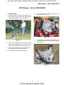
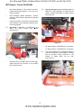
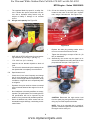
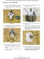
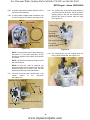
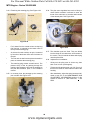
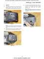
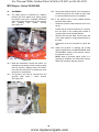
For Discount White Outdoor Parts Call 606-678-9623 or 606-561-4983
Service Manual
2006 MTD Single Cylinder Engine 350/450/650 Series “First Look”
NOTE: These materials are for use by trained technicians who are experienced in the service and repair of outdoor power
equipment of the kind described in this publication, and are not intended for use by untrained or inexperienced individuals.
These materials are intended to provide supplemental information to assist the trained technician. Untrained or inexperienced individuals should seek the assistance of an experienced and trained professional. Read, understand, and follow
all instructions and use common sense when working on power equipment. This includes the contents of the product’s
Operators Manual, supplied with the equipment. No liability can be accepted for any inaccuracies or omission in this publication, although care has been taken to make it as complete and accurate as possible at the time of publication. However, due to the variety of outdoor power equipment and continuing product changes that occur over time, updates will be
made to these instructions from time to time. Therefore, it may be necessary to obtain the latest materials before servicing
or repairing a product. The company reserves the right to make changes at any time to this publication without prior notice
and without incurring an obligation to make such changes to previously published versions. Instructions, photographs and
illustrations used in this publication are for reference use only and may not depict actual model and component parts.
© Copyright 2005 MTD Products Inc. All Rights Reserved
MTD Products Inc - Product Training and Education Department
FORM NUMBER - 769-02092A
10/2005
www.mymowerparts.com
For Discount White Outdoor Parts Call 606-678-9623 or 606-561-4983
TABLE OF CONTENTS
Introduction.....................................................................................................................: 1
Service Intent ..................................................................................................................2
Major failures not covered under warranty ......................................................................3
Minor failures not covered under warranty ......................................................................3
Maintenance and Adjustment Information .......................................................................3
Starter Service ...............................................................................................................13
Ignition System ..............................................................................................................17
Fuel System ..................................................................................................................21
Exhaust .........................................................................................................................29
Governor .......................................................................................................................30
Crankcase Ventilation ...................................................................................................31
Cylinder Head Removal ................................................................................................33
Torque Specifications ....................................................................................................36
Maintenance Intervals ...................................................................................................36
Maintenance Specifications ...........................................................................................37
www.mymowerparts.com
For Discount White Outdoor Parts Call 606-678-9623 or 606-561-4983
MTD Engine - Series 350/450/650
MTD Engine - Series 350/450/650
1.5.
1.
INTRODUCTION:
1.1.
MTD has chosen to introduce three MTD exclusive engines for walk-behind and self-propelled
mowers for the 2006 season. See Figure 1.1.
The Series 350 and Series 450 share some
basic parts. See Figure 1.5.
Series 350 / Series 450 Engine
Ignition
module
Figure 1.5
1.6.
Figure 1.1
1.2.
They will be designated with as Series 350,
Series 450, and Series 650. The series number
does not imply displacement or power out-put.
1.3.
These nominal designations correspond to factory numbers P61, P65, and P70 series.
1.4.
The 3rd and 4th digits are the bore in mm.
The major castings and some architecture of the
Series 650 differs from the two smaller engines.
See Figure 1.6.
Series 650 Cut-away engine
Round bulge
in carburetor
side of the
engine block
Ignition
module
Figure 1.6
1
www.mymowerparts.com
For Discount White Outdoor Parts Call 606-678-9623 or 606-561-4983
MTD Engine - Series 350/450/650
•
The service procedures are similar enough that
all three engines will be covered in this manual.
•
Individual differences will be noted in the text
and tables where necessary.
•
The most obvious feature that distinguishes the
two engine blocks is the location of the ignition
module.
2.
SERVICE INTENT
2.1.
The engines are warranted for two years against
defects in materials and workmanship, as
described in the warranty that accompanies the
mower.
2.2.
Because MTD is entering a new field, dealers
can assume that MTD will be very interested in
scrutinizing any failed parts that dealers replace
under warranty during the ‘06 and ‘07 mowing
season.
2.3.
Major engine failures will be repaired using service engines, short blocks, cylinder head assemblies, or long blocks.
•
The module is mounted above the cylinder on
the Series 350 and Series 450 engines, off-set
slightly to the intake side. See Figure 1.5.
•
The module is mounted about 90 degrees from
the cylinder on the Series 650 engine blocks.
See Figure 1.6.
1.7.
The Series 650 engine may have a steel or plastic cam and a very robust compression release
mechanism. The Series 350 and 450 use polymer cams
•
The repair method will depend on the nature of
the damage to the engine. Service engines will
most-likely be prevalent.
•
While some components of the MTD engines
may be visually similar to those of other manufacturers, none of the proprietary parts are
directly interchangeable.
The dealer should do any diagnostic disassembly needed to discern lubrication and abuse failures from defects in material or workmanship,
and file a warranty claim for the time allowed.
2.4.
Realistically, service will be limited primarily to
external components.
•
It is not anticipated that dealers will be doing
machine-work intensive rebuilds because it is
not cost effective.
•
Internal specifications that would be relevant to
such rebuilding are not included in this manual.
1.8.
NOTE: The procedures detailed in this manual
are intended for use by trained technicians who
are experienced in the service and repair of outdoor power equipment. Persons who are
untrained or inexperienced in this field should
seek the assistance of an authorized service
dealer.
NOTE: This manual was developed using preproduction equipment. Although it is current and
correct at the time of writing, it is subject to
change without notice.
2
www.mymowerparts.com
For Discount White Outdoor Parts Call 606-678-9623 or 606-561-4983
MTD Engine - Series 350/450/650
3.
MAJOR FAILURES NOT COVERED UNDER
WARRANTY
5.
MAINTENANCE AND ADJUSTMENT INFORMATION
NOTE: The following is a list of typical non warrantable scenarios. It is meant to provide illustration of the intended principles of the warranty.
Non-warrantable repairs include, but are no limited to the items on this list.
5.1.
Fasteners: All threaded fasteners used on the
engine are metric, with the following exceptions:
•
A 13/16” or 21mm wrench are suitable for spark
plug removal.
•
Series 350 and Series 450 engines are secured
to mower decks using a 3/8” self-tapping screw.
Remove them using a 9/16” wrench.
•
Series 650 engines are secured to the mower
decks using metric nuts and bolts. Remove
them using a pair of 14mm wrenches.
•
The crankshafts of all engines in this manual are
tapped with a 1/2”-20 thread, and the bolts can
be removed using a 5/8” wrench.
3.1.
Ingestion of dirt through the intake (air filter/carburetor)
3.2.
Lubrication failure
3.3.
Bent crankshaft
3.4.
Overheated by obstructed cooling system
3.5.
Corrosion or water damage
3.6.
Second year carburetor failures.
4.
MINOR FAILURES NOT COVERED UNDER
WARRANTY
5.2.
Spark plug: Torch model F7RTC, gapped to
.024”-.032” (.60-.80 mm).
NOTE: The following is a list of typical non warrantable scenarios. It is meant to provide illustration of the intended principles of the warranty.
Non warrantable repairs include, but are no limited to the items in this section.
•
Champion RN14YC or NGK BPR4ES are physically similar but may not match the F7RTC in
heat range. This difference in heat ranges will
effect performance and emissions. It is recommended that the Torch F7RTC plug be used for
service.
•
Wear rate will vary somewhat with severity of
use. If the edges of the center electrode are
rounded-off, or any other apparent wear / damage occurs, replace the spark plug before operating failure (no start) occurs.
5.3.
Cleaning the spark plug:
•
Use of a wire brush may leave metal deposits on
the insulator that cause the spark plug to shortout and fail to spark.
•
Use of abrasive blast for cleaning may leave
blast media in recesses in the spark plug. When
the media comes loose during engine operation,
severe and non-warrantable engine damage
may result.
•
Abrasive blast cleaning with organic media such
as walnut shells is acceptable.
5.4.
Inspection of the spark plug can provide indications of the operating condition of the engine.
•
Light tan colored deposits on insulator and electrodes is normal.
•
Dry, black deposits on the insulator and electrodes indicate an over-rich fuel / air mixture (too
much fuel or not enough air)
4.1.
Sheared flywheel key
4.2.
Stale, out-of-date, or improper fuel
4.3.
Damage from improper storage
4.4.
Damage caused by animals / insects
4.5.
Impact damage
4.6.
Normal maintenance or adjustment items.
4.7.
Recoil starter rope damage that is not the direct
result of a defect in materials or workmanship.
3
www.mymowerparts.com
For Discount White Outdoor Parts Call 606-678-9623 or 606-561-4983
MTD Engine - Series 350/450/650
•
Wet, black deposits on the insulator and electrodes indicate the presence of oil in the combustion chamber.
•
Heat damaged (melted electrodes / cracked
insulator / metal transfer deposits) may indicate
detonation.
•
A spark plug that is wet with fuel indicates that
fuel is present in the combustion chamber, but it
is not being ignited.
5.5.
Idle speed: If applicable, is 1,800 RPM + 160
RPM, set using throttle stop screw.
See Figure 5.5.
5.6.
Top no-load speed varies with blade length per
ANSI B71.1-1984 standard of 19,000 feet per
minute, allowing 200 RPM for safety margin:
See Figure 5.6.
Digital tachometer confirms safe
operating speed
Figure 5.6
Figure 5.5
•
•
20” blade models: 3,300 RPM max., all engines.
•
21” blade models: 3,100 RPM max., all engines.
5.7.
Top no-load speed may be adjusted slightly to
meet this specification by bending the bracket
that the governor spring connects to. The
bracket is visible under the air filter.
See Figure 5.7.
Increase spring tension to
increase engine speed
Idle speed is not normally critical in mower applications because the operator is not provided
with a throttle control.
Decrease spring tension to decrease
engine speed.
Figure 5.7
4
www.mymowerparts.com
For Discount White Outdoor Parts Call 606-678-9623 or 606-561-4983
MTD Engine - Series 350/450/650
•
The regulated blade tip speed is a safety feature. A dealer who puts a mower back into service with a defeated safety feature may be
subject to liability if damage or an accident
occurs.
5.8.
Oil type and capacity: See Figure 5.8.
5.10. Oil can be drained by removing the drain plug
located at the base of the filler tube / dipstick
tube, using a 10mm wrench. See Figure 5.10.
Insert but do not thread-in
dipstick to check oil level
Base of dipstick tube
Aluminum sealing washer
Drain Plug
Figure 5.10
•
Replace the drain plug sealing washer with a
new one to ensure that it does not leak.
•
Tighten the drain plug to a torque of 84 in-lb. (10
Nm) on installation.
Figure 5.8
•
SAE 10W-30 SF/CD API rating for most operating conditions up to 97 deg. F. (36 deg. C.)
•
17.0 - 20.3 fl.oz. (0.5 - 0.6 liters)
•
Insert but do not thread-in dipstick to check oil
level.
•
The oil level is determined by the lowest point on
the dipstick that is completely covered with oil.
5.9.
Special notes on oil:
•
Check the oil level more frequently and change
the oil more frequently in severe operating conditions such as high ambient temperature, dusty
conditions, or high load use in exceptionally thick
or tall grass.
•
Synthetic oil may be used, but it does not extend
service intervals because the engine oil is not filtered.
•
No oil additives or viscosity modifiers are recommended. The performance of oil meeting the SF/
CD specification will not be improved by the
addition of any commercially available products.
•
5.11. Alternatively, the mower may be tipped on its
side and the dipstick removed to drain the oil into
pre-positioned drain pan. See Figure 5.11.
Figure 5.11
CAUTION: Disconnect the high tension lead
from the spark plug and ground the lead before
doing any work that exposes the blade.
Some oil additives may cause severe and nonwarrantable engine damage, constituting a lubrication failure.
NOTE: If the oil is noticeable thin, or smells of
gasoline, carburetor repair will be needed before
the engine can be safely run.
5
www.mymowerparts.com
For Discount White Outdoor Parts Call 606-678-9623 or 606-561-4983
MTD Engine - Series 350/450/650
5.19. Confirm that the piston is at Top-Dead-Center on
the compression stroke. See Figure 5.19.
5.12. Fuel: Use clean, fresh fuel with a pump octane
rating of 87 or greater.
•
Stale or out-of-date fuel is the leading cause of
hard starting issues.
•
Pump octane ratings beyond 87 will not improve
engine performance.
•
The gasoline can have a maximum of 10% ethanol or 15% MTBE.
•
Do not use E85 in MTD engines.
5.13. Valve lash can be checked and adjusted using
the following steps:
Valves closed
5.14. If the engine has been run, allow it to cool thoroughly. Position the mower for easy access to
the cylinder head.
Probe to confirm piston
is at TDC
5.15. Disconnect the high-tension lead from the spark
plug and ground it well away from the spark plug
hole.
Figure 5.19
5.16. Remove the spark plug using a 13/16” or 21mm
wrench. A flexible coupling or “wobbly” extension may help. See Figure 5.16.
Valve cover
TDC can be identified using the probe. The keyway in the PTO end of the crankshaft also corresponds with the crank pin (and piston) position.
•
The compression stroke can be distinguished
from the overlap stroke by the presence of air
pressure at the spark plug hole and the fact that
neither of the valves should move significantly
on the compression stroke.
•
There is an automatic compression release
mechanism that “bumps” the exhaust valve as
the piston rises on the compression stroke. At
TDC, the exhaust valve should be fully closed.
5.20. Check valve lash between each valve stem and
rocker
arm
using
a
feeler
gauge.
See Figure 5.20.
Spark plug hole
(plug removed)
Muffler
•
High tension lead
Setting exhaust valve lash
Figure 5.16
5.17. Remove the four bolts that secure the valve
cover using a 10mm wrench, and remove the
valve cover from the engine.
NOTE: If care is used not to damage the valve
cover gasket, it can be re-used.
5.18. Secure the safety bale with a spring clamp, and
slowly pull the starter rope until air can be heard
being expelled from the spark plug hole.
Figure 5.20
6
www.mymowerparts.com
For Discount White Outdoor Parts Call 606-678-9623 or 606-561-4983
MTD Engine - Series 350/450/650
5.21. Intake valve lash (top valve) should be .003”.005” (.10 + .02mm).
5.28. Install the valve cover, tightening the valve cover
screws to a torque of 71 in-lb (8 Nm).
5.22. Exhaust valve lash (bottom valve) should be
.005-.007” (.15 + .02mm).
5.29. Install the spark plug and tighten to a torque of
177-221 in-lbs (20 - 25 Nm).
5.23. Use a 10mm wrench to loosen the jam nut, and
a 14mm wrench to adjust the rocker arm fulcrum
nut. See Figure 5.23.
5.30. Release the spring clamp securing the safety
bail, start the engine and test run it long enough
to confirm correct operation.
Setting intake valve lash
5.31. Compression should be in the range of 70 + 25
PSI (5.2 + 1.7 Bar).
5.32. If the engine has been run, allow it to cool thoroughly.
5.33. Disconnect the high-tension lead from the spark
plug and ground it well away from the spark plug
hole. See Figure 5.16.
5.34. Remove the spark plug using a 13/16” or 21mm
wrench. A flexible coupling or “wobbly” extension may help.
5.35. Hold the safety bail and pull the starter rope several times to purge any fuel or oil from the combustion chamber.
NOTE: Air compresses readily, liquid does not.
Liquid in the combustion chamber will result in
an artificially high compression reading.
Figure 5.23
•
•
Tighten the rocker arm fulcrum nut to close-up
the clearance between the end of the valve stem
and the contact point on the rocker arm.
5.36. Install a compression gauge in the spark plug
hole.
Loosen the rocker arm fulcrum nut to open-up
the clearance between the end of the valve stem
and the contact point on the rocker arm.
5.37. Confirm that the gauge is “zeroed”, then hold the
safety bail and pull the starter rope repeatedly,
until the needle on the gauge has risen as far as
it is going to. See Figure 5.37.
5.24. Hold the fulcrum nut with a 14mm wrench,
tighten the jam nut to a torque of 88.5 in-lb.
(10Nm) using a 10mm wrench.
5.25. Double-check the clearance after tightening the
jam nut, to confirm that it did not shift. Re-adjust
if necessary.
5.26. Rotate the engine through several compression
cycles:
•
Observe the movement of the valve train.
•
Return the piston to TDC compression stroke
and re-check the valve lash to confirm consistent
movement of the valve gear, including the slight
bump to the exhaust valve from the automatic
compression release.
Compression gauge
Reading ~ 90 PSI
5.27. Clean-up any oil around the valve cover opening, clean the valve cover, replace the valve
cover gasket if necessary.
Figure 5.37
7
www.mymowerparts.com
For Discount White Outdoor Parts Call 606-678-9623 or 606-561-4983
MTD Engine - Series 350/450/650
5.38. Interpreting compression readings:
•
•
•
Near Zero (< 20PSI [1.38 Bar]): most likely a
stuck valve or too-tight valve lash, provided
starter rope pulls with normal effort.
Moderately low (20-45 PSI [1.38 - 3.1Bar]):
Valve seat damage or piston ring wear.
Leak-down test or compressed-air test will help
confirm if damage is isolated to valves or piston
rings.
Oil smoke in exhaust on throttle increase tends
to
indicate
piston
ring
wear.
Oil smoke in exhaust on over-run tends to indicate valve guide wear.
•
The cable should not bind. Replace the cable if
it is kinked, melted frayed, or damaged in any
other way that causes it to bind.
•
The brake arm on the engine should not bind.
•
Each can be lubricated with light penetrating oil
or a dry PTFE-based lubricant such as “Tri-Flow”
dry Teflon lubricant.
5.42. To replace the cable: See Figure 5.42.
Too high compression (>95 PSI [>6.55 Bar])
most likely indicates excessive valve lash,
negating the automatic compression release. It
may also indicate a partial hydraulic lock or
severe carbon deposits within the cylinder.
5.39. Stop switch and brake: The stop switch and
brake must be able to stop the blade from rotating within 3.0 seconds after the release of the
safety bail, per ANSI B71.1-2003 standard.
Releasing the engine control
cable from the bracket
5.40. Make sure that the mower conforms to these
standards by performing a stop test.
Figure 5.42
5.41. Check the movement of the cable and brake
mechanism. See Figure 5.41.
Engine control
cable
Safety bail in RUN position
•
Squeeze the safety bail ends together to release
the bail from the upper handle bar.
•
Releasing the bail from the handle bar will provide enough slack in the cable to unhook the Zfitting at the top of the cable from the bail.
•
After the bail end of the cable is unhooked, the
Z-fitting at the engine end of the cable can be
unhooked.
•
Squeeze the barbs together at the engine end of
the cable housing to disconnect it completely
from the engine.
•
Remove the nut and bolt that secure the cable to
the handle bar.
•
Reverse the removal process to install the cable,
then test the mower in a safe area before returning it to service.
Safety bail in OFF position
Figure 5.41
5.43. The brake pad should be replaced when the
thickness of the friction material is less than .25”
(6.35mm) at the thinnest spot.
8
www.mymowerparts.com
For Discount White Outdoor Parts Call 606-678-9623 or 606-561-4983
MTD Engine - Series 350/450/650
5.44. To replace the brake pad, remove the flywheel
as described in the IGNITION section of this
manual. See Figure 5.44.
5.49. There are two screws that hold the brake
assembly to the engine. They can be loosened
using an 10mm wrench. See Figure 5.49.
Screw:
pivot point
Brake pad
Nuts
Screw:
Adjustment
Figure 5.49
Figure 5.44
5.45. Remove the two nuts that hold the brake pad to
the brake arm using an 8mm wrench, and
remove the pad.
5.46. Apply a small amount of thread locking compound such as Loctite 242 (blue) to the threaded
studs on the new brake pad, and fasten it to the
brake arm using the two nuts previously
removed.
•
The screw near the base of the cylinder is a
pivot point.
•
The screw near the oil fill tube clamps the brake
mechanism in place via a slotted hole.
5.50. Use a spring clamp to hold the safety bail
against the upper handle bar.
5.51. Position the brake assembly so that the edge of
the brake pad that is nearest the slotted hole is
roughly .050” (1.27mm) from the flywheel, then
tighten the screws. See Figure 5.51.
5.47. Assemble the engine, reversing the disassembly
process. Adjust the brake arm if necessary.
5.48. Adjust the brake arm with the flywheel
installed, but the fan shroud, recoil assembly,
and engine cover removed.
NOTE: The shank of an unused drill bit may be
used as a feeler gauge
Drill bit used
for gauge
Figure 5.51
9
www.mymowerparts.com
For Discount White Outdoor Parts Call 606-678-9623 or 606-561-4983
MTD Engine - Series 350/450/650
5.55. The reading should be high when the bail is
pulled down, reflecting the resistance in the primary windings of the ignition module.
See Figure 5.55.
5.52. Run and test the mower in a safe area before
returning it to service.
5.53. To test the stop switch: locate the terminal that
connects the stop switch wire to the primary
windings
of
the
ignition
module.
See Figure 5.53.
Ground connection
Safety bail
in RUN
position
Stop switch
connection
Stop switch
Wire to
ignition model
Figure 5.55
5.56. Alternatively, a jumper wire could be connected
to the same locations. Use a commercially
available spark checker to see if the ignition is
working or not.
Figure 5.53
5.54. Connect an Ohm meter between the terminal
and a ground point. The reading should
approach zero when the bail is released, closing
the contacts. See Figure 5.54.
Ground connection
•
If the jumper disables the ignition, but releasing
the bail does not, the problem lies in the switch.
•
If the jumper does not disable the ignition, then
the wire that connects the switch to the ignition
may have a fault, or the ignition module itself
may be faulty. Further investigation is required.
•
If the problem is a lack of spark when the bail is
pressed against the upper handlebar, disconnect
the wire from the switch using a 7mm wrench.
Isolate the wire from incidental contact with
ground,
and
test
the
ignition.
If it fails to spark, the wire may be shorted or the
ignition may be at fault. Further investigation is
required.
Safety bail in
OFF position
Stop
switch
connection
Figure 5.54
10
www.mymowerparts.com
For Discount White Outdoor Parts Call 606-678-9623 or 606-561-4983
MTD Engine - Series 350/450/650
5.57. If further investigation is required, remove the
recoil assembly, as described in the STARTER
SERVICE
section
of
this
manual.
See Figure 5.57.
5.61. Resistance (Ohms) should be infinite (O.L) with
the bail depressed. See Figure 5.61.
Fan shroud
Mounting posts for
engine cover
Safety bail in RUN
position, Module
primary windings
not grounded
Studs for recoil assembly
Figure 5.61
Figure 5.57
5.62. If the switch and wire work properly, and the connection is good at the spade terminal, but releasing the bail fails to stop the engine, then the
problem lies within the module.
5.58. Lift the fan shroud off of the studs that locate it.
5.59. Visually trace the wire from the stop switch to the
spade terminal on the module, and inspect the
wire for any damaged insulation or potential contact with ground.
5.63. Blade: A sharp, balanced, and well secured
blade is important.
5.64. A dull blade will bludgeon the grass rather than
cutting it.
5.60. Unplug the wire from the spade terminal on the
module, and check continuity to ground from the
female spade terminal on the wire. Resistance
(Ohms) should approach zero with the bail
released. See Figure 5.60.
•
This results in poor cut quality because the
grass is torn rather than cut, and the additional
drag can pull-down engine RPMs when the
mower is near the limits of its capacity.
•
A dull blade makes the engine work harder,
increasing operating temperature and fuel consumption, while decreasing engine life.
•
A dull blade, in combination with other abuse
issues may constitute abuse, voiding the warranty.
Safety bail in OFF
position, Module
primary windings
are grounded
Figure 5.60
11
www.mymowerparts.com
For Discount White Outdoor Parts Call 606-678-9623 or 606-561-4983
MTD Engine - Series 350/450/650
5.68. When it is necessary to tilt the mower, tilt it so
that the carburetor is up. When tilting to the side,
this will place the dipstick toward the ground.
The mower may also be positioned on the bench
as shown below, if the fuel tank is empty or the
fuel cap is sealed. See Figure 5.68.
5.65. An imbalanced or bent blade (sometimes in
accompanied by a bent crankshaft) creates
vibration.
•
This vibration makes the mower unpleasant to
use and will damage the mower.
•
Typical complaints include parts falling-off.
•
In extreme cases the engine crankcase or
mower deck may crack or separate from each
other.
CAUTION: Continued operation with a damaged
blade or crankshaft will create safety issues.
Empty fuel
tank, or seal
fuel cap with
plastic wrap
between cap
and threads
CAUTION: Under NO CIRCUMSTANCES
should a blade or crankshaft be straightened
and re-used. Any dealer or operator who does
so is subjecting themselves to extreme risk of
injury and liability.
NOTE: Impact damage to the blade and/or
crankshaft is not warrantable except as a victim
part of a specific failure of the damaged mower.
Examples would be a baffle or axle from the
damaged mower coming loose and contacting
the blade.
Figure 5.68
CAUTION: Disconnect the high tension lead
from the spark plug and ground the lead before
doing any work that exposes the blade.
NOTE: Secondary vibration damage is not warrantable. A customer who continues to operate
a mower with a damaged blade or crankshaft
does so at their own risk.
5.69. If the blade is removed for any reason, make a
visual inspection of all blade mounting hardware.
See Figure 5.69.
5.66. Impact damage to the blade or crankshaft is
often accompanied by impact damage to the flywheel or key. Flywheel and flywheel key damage are not warrantable, and will be considered
abuse unless there is very specific evidence of a
defect in material or workmanship on the part of
MTD.
Blade
Belleville
blade
support
5.67. Use of non-OEM blades, blade adaptors, and
hardware is not recommended for MTD mowers.
Blade
adaptor
Blade bolt
Figure 5.69
CAUTION: At no time should any part of the
body be placed in the path that the blade would
follow if it were to rotate.
12
www.mymowerparts.com
For Discount White Outdoor Parts Call 606-678-9623 or 606-561-4983
MTD Engine - Series 350/450/650
5.70. When servicing the blade:
6.
STARTER SERVICE
•
Replace any parts that are damaged or suspect.
6.1.
•
Use a commercially available blade stop tool or
a firmly positioned length of dimensional lumber
to keep the blade from rotating during removal
and installation.
To Remove recoil assembly from the mower,
remove the fuel cap.
•
Tighten the blade bolt to a torque of 450-600 inlbs. (51-68 Nm).
•
Test run the mower in a safe area before returning it to service.
CAUTION: Use common sense when working
around fuel: No sources of sparks or open flame
should be near enough to cause ignition.
NOTE: The rotating mass of the blade is important to the smooth operation of the engine.
6.2.
Loosen the wingnut that secures the starter rope
eyelet to the handlebars to provide clearance for
removing / installing starter rope.
6.3.
Remove the four screws that hold the engine
cover to the engine. See Figure 6.3.
Engine cover
CAUTION: The engine will be difficult or impossible to start with the blade removed, and the
resulting “kick-back” through the starter rope
may cause painful hand injuries. Do not attempt
to start the mower without a properly attached
blade.
Mounting screws
Figure 6.3
6.4.
Remove the engine cover and replace the fuel
cap.
6.5.
Remove the three nuts that secure the recoil
assembly and fan shroud to the engine using a
10mm wrench. See Figure 6.5.
Fuel cap
Recoil assembly
Fuel tank
Nuts
Figure 6.5
13
www.mymowerparts.com
For Discount White Outdoor Parts Call 606-678-9623 or 606-561-4983
MTD Engine - Series 350/450/650
6.6.
Lift the recoil assembly off of the engine, and
place it on a convenient work surface.
6.7.
Inspect the inside of the starter cup portion of the
flywheel casting. See Figure 6.7.
•
Replace the rope with 83” (2.1 meters) of #4
recoil rope, with ends heat-sealed to prevent
fraying, and wound 6 turns counter-clockwise for
tension.
6.10. If further damage is suspected, the recoil may be
disassembled by removing the shoulder screw
and pressure plate using a 10 mm wrench.
See Figure 6.10.
Starter cup
(cast into flywheel)
Pressure plate
Shoulder screw
Figure 6.7
6.8.
If the starter was failing to engage the flywheel,
and the edges of the teeth inside the cup are
rounded, replace the flywheel.
•
If the flywheel is replaced, the stater pawls or the
complete starter should be replaced as well, to
prevent a repeat failure.
6.9.
The most common failure mode for most recoil
assemblies is a broken rope. See Figure 6.9.
Figure 6.10
6.11. Beneath the pressure plate is a compression
spring, and two starter pawls that are held in the
disengaged position by two torsion springs.
6.12. Inspect the pawls and torsion springs for wear
and damage. See Figure 6.12.
Recoil assembly,
removed from mower
Torsion springs
L-shaped arm goes outside
of the starter pawl, on installation
Figure 6.9
•
Figure 6.12
If the spring was not damaged when the recoil
sprung back, It is possible to simply remove the
remnants of the old rope.
CAUTION: Eye protection should be worn if the
starter pulley is to be removed.
14
www.mymowerparts.com
For Discount White Outdoor Parts Call 606-678-9623 or 606-561-4983
MTD Engine - Series 350/450/650
6.13. Carefully lift the spring and pulley out of the
recoil housing. See Figure 6.13.
6.17. Install the torsion springs and pawls so that the
long arm of the spring reaches outside of the
pawl, and draws it toward the center of the
assembly. See Figure 6.17.
Pulley
Spring
Shoulder screw
Housing
Pressure plate
Compression spring
Pawl
Torsion
spring
Lithium grease
Figure 6.13
Figure 6.17
NOTE: The spring is nested within the starter
pulley. Service intent is to supply both parts
assembled under a single part number.
6.18. The rolled end of the pawl fits in the recess in the
starter pulley. The hooked end engages the
starter cup. Both the roll and the hook face
inward.
NOTE: If the spring is undamaged, but has been
removed from the pulley, the spring may be rewound. Engage the hook in the end of the spring
with the slot in the outer lip of the recess that the
spring fits in, and wind the spring into the recess
in a counter-clockwise direction.
6.19. The extrusions on the pressure plate should fall
inside of the pawls as the starter is assembled.
NOTE: Drag on the pressure plate, from the friction between the compression spring and the
head of the shoulder screw causes these extrusions to force the pawls outward, engaging the
starter cup.
6.14. Evaluate the damage, including parts prices and
local labor rates. In some parts of the country, it
makes economic sense to replace the complete
assembly, in other areas labor rates favor repair.
6.15. On assembly, apply a small amount of lithiumbased chassis grease to the surface of the recoil
housing that contacts the spring.
6.20. Apply a small amount of thread locking compound such as Loctite 242 (blue) to the threads
of the shoulder screw, and install the screw.
Tighten it to a torque of 71 - 88.5 in-lb. (8 - 10
Nm).
6.16. Carefully position the pulley and spring in the
recoil housing. Rotate the pulley gently counterclockwise until the spring seats, allowing the pulley to fall into position.
6.21. Wind the pulley 6 turns in the counter-clockwise
direction, to tension the spring. Align the rope
hole in the pulley with the rope eyelet in the
recoil housing, and secure it with a spring clamp.
15
www.mymowerparts.com
For Discount White Outdoor Parts Call 606-678-9623 or 606-561-4983
MTD Engine - Series 350/450/650
6.25. If starter rope tension needs to be adjusted,
there is room between the recoil housing and the
pulley to wind-on more tension. See Figure 6.25.
6.22. Heat fuse the ends of a 9’ (3 meter) length of #4
starter rope, and tie a double half-hitch in one
end.
6.23. The rope may be easily installed from the insideout. Pull the rope tight to seat the knot firmly in
the recess in the back of the pulley.
See Figure 6.23.
Rope-return tension may
be increased by winding
the rope and pulley
clockwise.
Spring clamp
maintains tension
while rope
is installed
Press knot
fully into
groove
Figure 6.25
6.26. Install the starter and tighten to a torque of 80 106 in-lbs. (9 - 12 Nm).
Figure 6.23
6.24. Install the handle and handle insert on the loose
end of the rope, again using a double half-hitch.
See Figure 6.24.
Inset: knot
Figure 6.24
16
www.mymowerparts.com
For Discount White Outdoor Parts Call 606-678-9623 or 606-561-4983
MTD Engine - Series 350/450/650
7.5.
7.
IGNITION SYSTEM
7.1.
The ignition system is a transistorized magneto,
contained in a single module.
•
The magneto is a three leg design.
•
The magneto is energized by the passing of a
pair of magnets mounted in the flywheel.
•
Ignition timing is set by the location of the flywheel in relation to the crankshaft. Proper timing
is maintained by a steel key.
7.2.
Remove the recoil assembly as described in the
STARTER SERVICE section of this manual.
7.3.
Lift the fan shroud off of the three studs that
locate it. See Figure 7.3.
Hold the safety bail down using a spring clamp,
and remove the flywheel using an appropriate
puller.
CAUTION: If the flywheel shows any signs of
physical damage such as cracks, broken vanes,
or damaged key-way, replace it. A damaged flywheel poses a threat of burst failure. Burst failures are extremely hazardous to surrounding
people and property.
7.6.
Inspect the key, keyway, and tapered mating surfaces of the flywheel and crankshaft.
See Figure 7.6.
Key
Fan shroud
Taper
Shoulder
bushings
Shoulder
bushings fit
over studs
Figure 7.6
7.7.
Figure 7.3
7.4.
To remove the flywheel, remove the flywheel nut
using a 19mm wrench. See Figure 7.4.
The ignition module for the Series 350 and
Series 450 engines is mounted to the cylinder.
See Figure 7.7.
Module
Figure 7.7
Figure 7.4
17
www.mymowerparts.com
For Discount White Outdoor Parts Call 606-678-9623 or 606-561-4983
MTD Engine - Series 350/450/650
7.8.
The ignition module for the Series 650 engines
is mounted off-set from the cylinder.
See Figure 7.8.
Series 650 engine: note module location
and length of high tension lead
Spark
plug
One leg of the module is secured by a stud that
also supports the fan shroud, the second leg is
secured by a screw.
•
On Series 350 and Series 450 engines, there is
a spacer between the cylinder and the module at
both mounting points.
•
On the Series 650 engines, there is a spacer
between the module and the crankcase on the
stud only.
•
On module installation, set the air gap, tighten
the stud and screw to a torque of 84 in-lb (10
Nm), then re-check the air gap.
7.14. Diagnosis: refer to steps 5.53 through 5.62 of
the MAINTENENACE AND ADJUSTMENT
INFORMATION section of this manual to isolate
the ignition coil from the stop switch.
Module
7.15. Normal performance of the coil is to produce at
least 10,000 volts at starter-rope pull-through
speed. See Figure 7.15.
Figure 7.8
7.9.
•
The ignition modules differ between the two
basic engine designs, because of the longer distance from the module to the plug on the Series
650 engines. The high tension lead from the
module to the spark plug is longer on these
engines than on the smaller ones.
7.10. The flywheels are interchangeable between the
two engine designs. Even though the module is
mounted in different locations, the relationship
between the key-way and the magnets is the
same. The keyways in the crankshafts are
indexed differently to suit the module location.
Inexpensive spark gap tester
provides usable information
7.11. On installation, confirm that the key is properly
seated in the key-way, and that the tapers are
fully seated. Key or keyway failure may result
from improper seating.
Figure 7.15
7.12. Install the flywheel nut to a torque of 41-48 ft-lbs.
(55-65 Nm).
7.16. Presence or absence of strong spark, with the
stop switch and wire known to be good, is generally enough to identify the ignition coil as good or
bad. Resistance readings may help confirm the
source of the failure, but are generally unnecessary.
7.13. Use a 10mm wrench to remove the ignition module or adjust the air gap between the module and
the flywheel.
•
The air gap should be .016”-.024” (.4-.6mm).
•
The module is attached with the high-tension
lead facing up.
7.17. It is possible for the transistorized portion of the
module to fail, yet resistance tests will show the
windings to be good. A simple spark-gap tester
is will give an adequate indication of the ignition
system’s condition.
18
www.mymowerparts.com
For Discount White Outdoor Parts Call 606-678-9623 or 606-561-4983
MTD Engine - Series 350/450/650
7.18. Simple spark-testers are readily available and
inexpensive. Thexton Part # 404 is available
form a variety of retailers, and similar units are
available
form
other
manufacturers.
See Figure 7.18.
7.20. At pull-over speed (~ 600 RPM), voltage should
be at least 8,000. See Figure 7.20.
Pull-over speed: waveform is half-way
between 2nd and 3rd reticle (10,000 V.)
Instructions on
back of package
Figure 7.20
NOTE: Flash-over voltage will vary with spark
plug condition and gap.
Figure 7.18
NOTE: Pull-over speed may vary from operator
to operator.
7.19. At operating speed, the ignition should produce
voltage approaching 12,000. See Figure 7.19.
7.21. Resistance in the primary windings of the ignition module, measured between the spade terminal and the laminations, was observed to be in
the 550-650 Ω range. See Figure 7.21.
1 reticle = 4,000 Volts
waveform is
3 reticles tall
Probe to
laminations
Figure 7.19
Probe to stop switch
spade terminal
Figure 7.21
19
www.mymowerparts.com
For Discount White Outdoor Parts Call 606-678-9623 or 606-561-4983
MTD Engine - Series 350/450/650
7.25. Spark plug: refer to steps 5.2 through 5.4 in the
MAINTENANCE AND ADJUSTMENT INFORMATION section of this manual.
7.22. Resistance in the secondary windings of the
ignition module, measured between the spark
plug terminal and the laminations, was observed
to be in the 8K-9KΩ range. See Figure 7.22.
NOTE: There may be slight variation in specification due to production variation and other factors such as temperature.
•
Resistance figures that are vastly lower may
indicate a short in the windings being tested.
•
Resistance figures that are vastly higher (or O.L)
may indicate a fault in the windings being tested.
NOTE: Intermittent failure requires tests for voltage and resistance to be made when the engine
is cold, and again when it is hot.
Probe to spark
plug terminal
Probe to laminations
Figure 7.22
•
Typical customer complaint: “It stops after I mow
for 10 minutes and I can’t get it to re-start”.
•
To confirm that the problem is ignition-based, it
is necessary to “catch it in the act”.
•
Resistance
increases.
normally
7.23. Failure of the magnets in the flywheel is exceedingly rare. To test the magnets, simply hold an
item made of ferrous metal roughly 1/4”
(.635cm) away from the magnets in the flywheel.
It should be drawn to the flywheel. A wrench or
screwdriver is suitable for this test.
7.24. An inexpensive compass or bar magnet can be
used to confirm opposite polarity of the flywheel
magnets. See Figure 7.24.
Opposite poles of bar magnets
are attracted to opposite pole
flywheel magnets for the sake
of illustration
Figure 7.24
20
www.mymowerparts.com
rises
as
temperature
For Discount White Outdoor Parts Call 606-678-9623 or 606-561-4983
MTD Engine - Series 350/450/650
8.
FUEL SYSTEM
8.3.
The tank is
See Figure 8.3.
CAUTION: When working around the fuel system, do not bring any sources of heat, spark, or
open flame close enough to the work are to pose
a fire hazard.
Tank
•
Drain the fuel tank or clamp the fuel line before
starting work to prevent spillage.
Filter
•
Dispose of drained fuel in a safe and responsible
manner.
8.1.
The fuel tank is secured to a bracket on the back
of the engine by a screw and fender washer,
removable with a 12mm wrench, and a second
bolt, removable with a 10mm wrench.
See Figure 8.1.
vented
through
the
cap.
Cap liner / gasket
Cap
Sleeve (mtg. hole)
Hose barb
Figure 8.3
Screw and
fender washer
Screw
8.4.
To test the cap vent, a hand-pumped vacuum /
pressure tester may be connected to the fuel
barb (after draining). See Figure 8.4.
Hand-pump vacuum
/ pressure tester
connected to fuel line
Figure 8.1
8.2.
To remove the fuel tank:
•
Drain the tank.
•
Disconnect the fuel line from the tank.
•
Remove the fuel cap.
•
Unbolt, and remove the tank.
Figure 8.4
21
www.mymowerparts.com
For Discount White Outdoor Parts Call 606-678-9623 or 606-561-4983
MTD Engine - Series 350/450/650
8.5.
The tank should not hold any pressure nor any
vacuum.
•
Replace the cap if either pressure or vacuum
builds using the hand-pump tester.
•
A cap that maintains pressure will cause the
engine to run rich as the fuel in the tank heats
and expands, forcing it’s way past the float valve
in the carburetor.
•
A cap that maintains vacuum will cause the
engine to run lean as the fuel is depleted, but no
air comes in to replace it.
•
The two conditions may both be present, but the
symptoms vary with fuel, fuel level, and operating conditions.
•
Usually presents as a “Runs and quits” scenario.
8.6.
All models are equipped with a manual choke,
operated by a pull-knob on the handlebar.
See Figure 8.6.
8.7.
If the choke plate fails to close fully when the
knob is pulled, the mower will be difficult or
impossible to start when cold.
8.8.
The rod connecting the choke lever to the choke
arm on the carburetor can be bent slightly to
facilitate adjustment. See Figure 8.8.
Choke rod
Figure 8.8
Choke lever
NOTE: Stale, contaminated, or out-dated fuel is
a leading cause of no-start situations. If the fuel
in the tank, lines, or carburetor is suspect, it may
be easily drained.
8.9.
Choke cable
Make provisions to safely catch and dispose of
drained fuel before draining it.
Figure 8.6
22
www.mymowerparts.com
For Discount White Outdoor Parts Call 606-678-9623 or 606-561-4983
MTD Engine - Series 350/450/650
8.10. Remove the drain bolt from the carburetor float
bowl using a 10mm wrench, and let the fuel flow
out of the system. See Figure 8.10.
8.12. The air filter assembly is easily removable using
a 10mm wrench. See Figure 8.12.
Crankcase vent tube
Oil drain extension tube
MTD P/N: 731-1682A
Filter mounting screw
and nuts
Figure 8.12
Figure 8.10
•
•
Disconnect the crankcase vent tube.
The bowl drain may also be used to prevent fuel
spillage during carburetor removal.
•
Remove the screw that holds the air filter housing to the control bracket.
NOTE: There is a gasket between the head of
the drain bolt and the bowl.
•
Remove the two nuts that hold the air filter body
to the carburetor mounting studs.
NOTE: the torque for the drain bolt is 80 - 106
in-lbs. (9 - 12 Nm).
•
Lift away the filter housing.
8.13. Behind the filter housing is a steel plate with
formed rubber gaskets vulcanized to each surface. See Figure 8.13.
8.11. The air filter and pre-filter are easily accessible
behind the air filter cover. See Figure 8.11.
Filter cover
Filter element
Pre-filter
Gasket / plate
Figure 8.11
Figure 8.13
23
www.mymowerparts.com
For Discount White Outdoor Parts Call 606-678-9623 or 606-561-4983
MTD Engine - Series 350/450/650
8.17. After the second stud is removed, the carburetor
can be maneuvered to disconnect the linkages.
See Figure 8.17.
8.14. Note or mark the orientation of the plate.
Notches in the plate allow air to reach emulsion
ports: one for the main jet and one for the pilot
jet. Channels in the rubber provide air passage
to the choke-side bowl vent.
CAUTION: When working around the fuel system, do not bring any sources of heat, spark, or
open flame close enough to the work are to pose
a fire hazard.
•
Drain the fuel tank or clamp the fuel line before
starting work to prevent spillage.
•
Dispose of drained fuel in a safe and responsible
manner.
8.15. To remove the carburetor, disconnect the fuel
line.
Note: washer between nuts
8.16. Double-nut the studs for removal, with a washer
between the nuts serrated faces of the nuts.
See Figure 8.16.
Figure 8.17
8.18. Rotate the throttle arm until it meets the idle
speed screw, then pivot the carburetor slightly to
disengage the 90 degree bend at the end of the
governor rod. See Figure 8.18.
Governor rod
Throttle arm
Stud removal:
double-nut method
Figure 8.16
NOTE: There are differences between the linkages on the Series 650 carburetor, and those
shared by the Series 350 and Series 450.
Removal technique is similar.
Figure 8.18
24
www.mymowerparts.com
For Discount White Outdoor Parts Call 606-678-9623 or 606-561-4983
MTD Engine - Series 350/450/650
8.19. Pivot the carburetor to disengage the Z-fitting on
the end of the choke rod. See Figure 8.19.
8.21. Between the carburetor and the cylinder head is
an insulator, sandwiched between two gaskets.
See Figure 8.21.
Insulator
Bowl vent channel
Gasket: Insulator
to carburetor
Choke rod
Choke arm
Gasket: insulator
to cylinder head
Figure 8.19
Figure 8.21
8.20. Unhook the stabilizer spring that takes-up the
play between the governor arm, the governor
rod, and the throttle arm on the carburetor.
NOTE: The gaskets are different, and there is an
orientation to the insulator.
NOTE: The carburetors used on all three
engines are similar in design, but differ in calibration.
NOTE: The jet markings may be used for identification purposes, but the technician should not
attempt to infer orifice sizes from the identification numbers.
NOTE: Installing the wrong main jet, or a carburetor with the wrong main jet will produce performance and emissions issues.
•
The gasket with the “D” shaped opening goes
between the insulator and the cylinder head,
matching the shape of the gasket to the shape of
the intake port.
•
The bowl vent channel in the insulator faces the
carburetor, with the exit toward the bottom.
•
There is a small hole in the insulator to carburetor gasket. The hole should be aligned to allow
passage of air through the bowl vent channel to
the throttle side bowl vent in the carburetor body.
25
www.mymowerparts.com
For Discount White Outdoor Parts Call 606-678-9623 or 606-561-4983
MTD Engine - Series 350/450/650
8.25. When inverted, the float should rest in a level
position. See Figure 8.25.
8.22. There is a corresponding passage recessed into
the mating surface where the throttle end of the
carburetor
housing
meets
the
gasket.
See Figure 8.22.
Float pin
Float
Float valve
Bowl vent port
Fuel inlet
Bowl vent
channel
Figure 8.25
Figure 8.22
8.26. Remove the pin that the float hinges on to
remove the float.
8.23. Bowl removal is a logical place to begin carburetor disassembly. Remove the bowl bolt using a
10mm wrench. See Figure 8.23.
8.27. The float is not adjustable. Spring tension
against the float valve begins to build from the
horizontal position, putting progressively more
pressure between the tip of the valve and the
seat. See Figure 8.27.
Float bowl
Drain bolt
Flat fiber
gasket
Float
Bowl bolt
with recess in
head for O-ring
Compression
spring
Gasket seal
Float valve
Figure 8.23
8.24. From this point an assessment can be made
about the viability of rebuilding the carburetor.
•
If extensive corrosion is evident, replace the carburetor.
•
If varnish build-up is too extensive to clean,
replace the carburetor.
Figure 8.27
8.28. Because the float valve is crucial to the functioning of the carburetor, and the viton tip of the
valve is subject to wear, it is suggested that technicians replace the valve and spring any time the
carburetor is disassembled for cleaning.
26
www.mymowerparts.com
For Discount White Outdoor Parts Call 606-678-9623 or 606-561-4983
MTD Engine - Series 350/450/650
8.29. A square cross-section gasket seals the bowl to
the body of the carburetor.
8.32. The throttle stop screw has a large pliable lip
around the head of the screw. That lip secures a
metering plug for the pilot and transition ports.
Remove the screw to remove reach the plug.
See Figure 8.32.
8.30. A narrow-shank straight blade screwdriver can
be used to remove the main jet. See Figure 8.30.
Main jet
Bowl gasket
Welch plug
Fuel feed leg
on central
column for pilot
and transition
shot plug in feed bore
Bowl vent port
Fuel port to
central column
Figure 8.30
Figure 8.32
NOTE: Fuel enters the central column through a
port about 1/2” (1cm) from the bottom, to help
prevent the ingress of any residue in the bottom
of the bowl.
8.33. The metering plug can be carefully pried out
using a small screwdriver. See Figure 8.33.
NOTE: The orifice in the main jet meters fuel into
the central column.
NOTE: Air from the main jet emulsion port
enters the central column near the top, then gets
bubbled through the emulsion tube into the
metered fuel flow to promote atomization.
8.31. The main jet secures the emulsion tube in the
central
column
of
the
carburetor.
See Figure 8.31.
Emulsion air port: main jet
Emulsion tube
Main jet
Figure 8.33
Emulsion air port: pilot jet
Bowl vent ports
Figure 8.31
27
www.mymowerparts.com
For Discount White Outdoor Parts Call 606-678-9623 or 606-561-4983
MTD Engine - Series 350/450/650
8.36. The pilot screw regulates how much of this premixed fuel/air emulsion is allowed to enter the
throat of the carburetor, to atomize down-stream
of the throttle plate. See Figure 8.36.
8.34. Examining the metering plug: See Figure 8.34.
Air passage
End view
Transition ports
Pilot port
Pilot screw
Fuel metering orifice
O-ring seals
Figure 8.34
•
Fuel, drawn from the central column via the long
fuel feed leg, is metered by the brass orifice in
the tip of the metering plug.
Figure 8.36
•
Air, drawn from the emulsion air port, is metered
by the size of the brass orifice at the entrance to
the port.
8.37. The transition ports are fixed. They are drilled
into the throat of the carburetor, down-stream of
the venturi. They lie behind the brass welch plug
near the pilot screw.
•
The fuel and air that feed the pilot and transition
ports are mixed at the metering plug.
8.38. Adjustment on installation:
•
The metering plug creates a small venturi. The
pressure drop of the air passing through the
metering plug draws the fuel into the passage to
the pilot and transition ports, in an emulsified
mixture.
8.35. In cut-away view, the passage by the metering
port is visible. See Figure 8.35.
•
Gently turn the pilot screw in all the way, then
back it out 3/4 turn (270 degrees).
•
Tighten the idle speed screw until 1/8” (3 mm) of
the screw is visible on the throttle arm side of the
housing.
•
After installation, adjust the speed screw as indicated in step 5.5 of the MAINTENANCE AND
ADJUSTMENT INFORMATION section of this
manual to achieve a 1,800 RPM idle, + 160
RPM.
Figure 8.35
28
www.mymowerparts.com
For Discount White Outdoor Parts Call 606-678-9623 or 606-561-4983
MTD Engine - Series 350/450/650
9.
EXHAUST
9.1.
The muffler and muffler cover are secured to the
cylinder head by nuts on studs. They may be
removed using a 10mm wrench. See Figure 9.1.
9.3.
The muffler gasket extends well beyond the port,
to act as a heat shield and cooling air guide
between the muffler and the cylinder.
See Figure 9.3.
NOTE: The exhaust gasket is a one time use
only gasket. Replace every time the muffler is
removed.
Figure 9.1
NOTE: The studs that hold the carburetor and
the studs that hold the muffler are interchangeable.
9.2.
Figure 9.3
The muffler and cover may be slipped off of the
studs as a unit, or separately. See Figure 9.2.
Figure 9.2
29
www.mymowerparts.com
For Discount White Outdoor Parts Call 606-678-9623 or 606-561-4983
MTD Engine - Series 350/450/650
10.
10.4. The governor shaft is splined. If it is necessary to
remove the governor arm, make an index mark
to orient the shaft to the arm on installation.
GOVERNOR
10.1. The engine speed is controlled by a balance
between the force applied by a spring (pulling
the throttle open) and a flyweight mechanism
within the engine applying force to the governor
arm
(pushing
the
throttle
closed).
See Figure 10.1.
10.5. If the governor arm is being installed without
benefit of index marks:
•
Rotate the governor shaft clockwise as far as it
will go.
•
Position the top of the arm about 3/16” (.476cm)
from the boss on the casting that provides a
mounting point for the fuel tank bracket.
•
Slide the arm onto the shaft. The flat on the top
of the shaft should be roughly perpendicular to
the shaft.
•
Tighten the nut on the clamp bolt to secure the
arm.
Governor action
10.6. Adjust the governor to maintain top no-load
speed as described in the MANTENANCE AND
ADJUSTMENT section of this manual, Instruction number 5.6 and 5.7.
Spring tension
NOTE: When a governed engine “hunts”, it is
generally an indication of a lean fuel/air mixture,
rather than a problem with the governor.
Figure 10.1
10.2. While the mechanism is simple and robust, it is
important to pay attention when working on parts
near the governor. Binding caused by interference with mis-routed lines or cables may make
the governor unresponsive.
10.3. The governor arm may be removed from the
governor shaft using a 10mm wrench.
See Figure 10.3.
Figure 10.3
30
www.mymowerparts.com
For Discount White Outdoor Parts Call 606-678-9623 or 606-561-4983
MTD Engine - Series 350/450/650
11.
CRANKCASE VENTILATION
11.1. The PCV chamber is vented to the air filter
through a molded rubber hose. The rubber hose
directs crankcase fumes to a covered duct within
the air filter housing. See Figure 11.1.
•
This case pressure can be measured using a
slack-tube water manometer, or an electronic
version of the same tool.
•
Less than (between zero and...) -1” ( -2.54cm) of
water is a typical reading.
11.3. An adaptor can easily be made form an old or
extra dipstick. See Figure 11.3.
Electronic manometer:
Adaptor made by drilling a
hole in a dipstick /
oil cap
Figure 11.1
11.2. When functioning properly, the PCV valve (Positive Crankcase Ventilation) works with the inherent pumping action of the piston in the bore to
expel extra pressure from the crankcase.
See Figure 11.2.
Figure 11.3
11.4. An engine that fails to purge extra case pressure
in a controlled manner will build case pressure.
The pressure will find it’s own way out of the
engine in undesirable ways.
•
Oil will be forced by the rings and valve guides,
being burnt in the combustion chamber.
•
The cause of this oil burning can be mistaken for
a worn-out engine, if proper diagnosis (compression, leak-down, and case pressure) is not performed.
11.5. Experimentation by MTD’s Training and Education department has revealed the following characteristics:
•
A leaky PCV system will not build-up substantial
case pressure.
•
A leaky PCV system will allow the engine to
ingest contaminants through the system, accelerating engine wear.
•
A blocked PCV system will allow crankcase
pressure to build very rapidly. Noticeable oil
fumes will be evident in the exhaust within several minutes of normal operation.
Figure 11.2
•
Normally, small engines run with slightly negative case pressure.
31
www.mymowerparts.com
For Discount White Outdoor Parts Call 606-678-9623 or 606-561-4983
MTD Engine - Series 350/450/650
11.9. The disc acts as a check valve: pressure pulses
force it off of the port, but it falls back over the
port when the pressure drops.
11.6. The PCV chamber is accessible by removing the
flywheel, as described in steps 7.2 through 7.6
of the IGNITION SYSTEM section of this manual. See Figure 11.6.
11.10. The folded wire mesh in the chamber also helps
separate the oil from the air. See Figure 11.10.
Dimple
PCV
chamber
cover
Disc
Port to
crankcase
Port to
PCV hose
PCV tube
Folded wire mesh
Figure 11.6
Figure 11.10
11.7. Remove the two screws that hold the PCV
chamber cover to the engine block using a
10mm wrench.
11.11. The port to the PCV hose is near the top of the
chamber. The oil tends to settle out of suspension, leaving mostly air to exit the chamber
through the PCV hose.
11.8. The cover and gasket can be separated from the
chamber. See Figure 11.8.
11.12. The screen accumulates droplets of oil, which
eventually drip down to the bottom of the chamber. Beneath the screen is a drain-back port,
leading to the crankcase. the size of the port is
small enough that significant pressure does not
flow through it. See Figure 11.12.
Cover
Gasket
Baffle
Disc
Figure 11.8
Drain-back port
NOTE: The dimple in the cover helps locate the
fiber disc over the port that leads into the crankcase.
NOTE: the baffle in the cover helps separate the
oil from the air in the chamber. It is desirable to
allow the air out, but important to keep as much
oil as possible in the engine.
Figure 11.12
32
www.mymowerparts.com
For Discount White Outdoor Parts Call 606-678-9623 or 606-561-4983
MTD Engine - Series 350/450/650
11.13. Vigorous pumping with a hand pump vacuum /
pressure tester will result in a slight build-up of
pressure within the chamber. See Figure 11.13.
12.
CYLINDER HEAD REMOVAL
12.1. It is recommended that the mower be positioned
on the bench vertically for cylinder head
removal. See Figure 12.1.
Figure 11.13
•
•
Figure 12.1
This 2-3 PSI (.14-.20 Bar) build-up will dissipate
through the drain-back port over the course of 510 seconds.
NOTE: This position provide easy access to
most service points, yet prevents undue oil spillage.
No vacuum should accumulate in the chamber
unless the drain-back port is blocked and the
disc is not moving from over the crankcase port.
NOTE: It is not absolutely essential to remove
the fan shroud, but taking the engine cover off
will ease access to some components.
12.2. Disconnect and ground the spark plug high tension lead, and remove the spark plug using a 13/
16” or 21mm wrench. See Figure 12.2.
Figure 12.2
33
www.mymowerparts.com
For Discount White Outdoor Parts Call 606-678-9623 or 606-561-4983
MTD Engine - Series 350/450/650
12.7. Double-nut and remove the exhaust studs, similar to the method used to remove the carburetor
studs in the FUEL SYSTEM section of this manual.
12.3. Remove the four screws securing the valve
cover using a 10mm wrench. See Figure 12.3.
12.8. Remove the carburetor as described in the
FUEL SYSTEM section of this manual.
See Figure 12.8.
Figure 12.3
12.4. Loosen the jam nuts and fulcrum nuts that
secure the rocker arms using a 10mm wrench
and a 14mm wrench.
Figure 12.8
12.5. Pivot the rocker arms aside, or remove them
completely, and remove the push rods.
12.9. Remove the cylinder head bolts using a 14mm
wrench. See Figure 12.9.
NOTE: Once broken-in, the rocker arm should
be kept with its corresponding valve.
Cylinder head
bolts
NOTE: The intake and exhaust push rods are
identical and interchangeable. It is preferable,
but not absolutely necessary to return the same
push rods to their original locations on engine
with substantial (>100 hours) operating time.
12.6. Remove the muffler, as described in the
EXHAUST
section
of
this
manual.
See Figure 12.6.
Figure 12.9
12.10. Lift the cylinder head off of the mower.
NOTE: The alignment dowels fit in two of the
head bolt holes.
12.11. Carefully clean all sealing surfaces of all gasket
residue. Do not scratch the sealing surfaces.
12.12. Make a visual inspection of the valves and cylinder bore to confirm the initial diagnosis.
Figure 12.6
34
www.mymowerparts.com
For Discount White Outdoor Parts Call 606-678-9623 or 606-561-4983
MTD Engine - Series 350/450/650
12.13. For inspection purposes, the valve retainers can
be removed with light finger pressure.
See Figure 12.13.
12.15. Position new cylinder head gasket and dowels
on engine block. See Figure 12.15.
NOTE: There is a right way and a
wrong way to install the head
gasket: holes should match
Dowel
Dowel
Figure 12.15
Figure 12.13
12.16. Position the cylinder head on the engine block.
12.14. Only the intake valve has a valve guide seal.
See Figure 12.14.
12.17. Install the 4 head bolts, and tighten them to a
step torque of 212 in-lb. (24 Nm) in an alternating diagonal pattern. See Figure 12.17.
1
3
4
2
Figure 12.14
Figure 12.17
NOTE: Outside of warranty, the dealer may
choose to recondition a cylinder head.
•
Replacement valve guides are not presently
available.
•
Valve spring free length should be at least 1.22”
(28.5mm). Original length is 1.44” (36.6mm).
•
Valve seats are 45 degrees, with a 15 degree
topping cut and a 75 degree narrowing cut.
•
Seat width should be .043”-.050” (1.1-1.3mm)
with a margin of .024” (.6mm) on the exhaust
valve and .027” (7mm) on the intake valve.
12.18. Insert the push rods.
12.19. Install and adjust the rocker arms as described
in steps 5.13 through 5.29 of the MAINTENANCE AND ADJUSTMENT section of this
manual.
12.20. Install the fuel and exhaust systems, using new
gaskets, as described in the FUEL SYSTEM and
EXHAUST SYSTEM sections of this manual.
12.21. Test run the mower in a safe area before returning it to service. Check all safety features.
35
www.mymowerparts.com
For Discount White Outdoor Parts Call 606-678-9623 or 606-561-4983
MTD Engine - Series 350/450/650
13.
TORQUE SPECIFICATIONS
Fastener Torque Table
14.
Fastener
Nuts, muffler
Nuts, carburetor
Screw, dipstick tube
Nuts, recoil housing
Screws, brackets
Screws, PCV cover
Studs, recoil mounting
and ignition module
Torque, SAE
84 in-lb
84 in-lb
84 in-lb
84 in-lb
84 in-lb
84 in-lb
Torque, metric
10 Nm
10 Nm
10 Nm
10 Nm
10 Nm
10 Nm
84 in-lb
10 Nm
Nut, flywheel
Bolt, blade
41-48 ft-lb
450-600 in-lb
55-65 Nm
51-68 Nm
Spark plug
Screws, valve cover
Jam nuts, rocker arm
Studs, rocker arm
Screws, cylinder head
175-220 in-lb
71 in-lb
84 in-lb
212 in-lb
212 in-lb
19.1-24.8 Nm
8 Nm
10 Nm
24 Nm
24 Nm
Screws, sump to block
84 in-lb
10 Nm
MAINTENANCE INTERVALS
Maintinance item
Check oil
Check air filter
Note on air filter
Note on pre-filter
Check blade condition
Check & gap spark plug
Check cooling fins
Change oil
Note on oil:
Change air filter
Note on air filter
Drain or preserve fuel
Fog or lube cylinder
Rotate engine to TDC
Each use
Each 25 hrs. use Each 50 hrs. use
*
*
Dirt may be shaken or tapped out of the air filter, but
compressed air is not to be used for cleaning. Do not
wash or oil paper filter element.
Foam pre-filter may be washed in water and mild
detergent, and re-used. Do not oil.
*
Replace if worn.
*
After prolonged storage
*
Change oil after first 5 hrs. of use, and before
prolonged storage.
*
Air filter and pre-filter life vary dramatically with
operating conditions.
Before prolonged storage
Before prolonged storage
Before prolonged storage
36
www.mymowerparts.com
For Discount White Outdoor Parts Call 606-678-9623 or 606-561-4983
MTD Engine - Series 350/450/650
15.
MAINTENANCE SPECIFICATIONS
Item
Ignition module
Spark plug
Spark plug
Oil type
Oil type
Oil
Specification
Setting. SAE
Setting, Metric
air gap
.008"-.016"
.2-.4mm
gap
.024"-.032"
.6mm-.8mm
type
Torch F7TC
SAE 30 SF/CD
32 to 104 deg. F.
0 to 40 deg. C.
SAE 10W30 SF/CD neg. 4 to 97 deg. F. neg. 20 to 36 deg. C.
volume
17.0-20.3 fl.oz.
0.5-0.6 L
Fuel
Pilot mix screw
Idle speed
Top no-load
Top no-load
Octane
setting
RPM
RPM 20" mower
RPM 21" mower
Valve lash
Valve lash
Intake
Exhaust
90 octane pump rating
Turn-out 180-270 degrees
1,600 + 160 RPM
3,400 RPM
3,250 RPM
.005"-.007"
.007"-.009"
37
www.mymowerparts.com
0.15 + .02mm
0.20 + .02mm