1
IMPORTANT MANUAL
Do Not Throw Away
Operator's
Manual
@
Model No.
358.356242
Always Wear Eye Protection
CRAFTSMAN+
READ
THE OPERATOR'S
WARNING
MANUAL AND FOLLOW
ALL WARNINGS AND
SAFETY
INSTRUCTIONS.
FAILURE TO DO SO CAN
RESULT IN SERIOUS
INJURY.
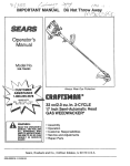
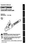
2.5 cu. in./40 cc 2-CYCLE
18 in. Guide Bar
GASOLINE CHAIN SAW
•
•
•
•
•
•
Assembly
Operation
Customer Responsibilities
Service and Adjustments
Repair Parts
Table of ContentsInside Back Cover
Sears, Roebuck and Co., Hoffman Estates, IL 60179 USA
530--083047-438/03/94
SAFETY RULES
&
WARNING:
....
ALWAYS DISCONNECT SPARK PLUG WIRE AND PLACE WIRE WHERE IT CANNOT CONTACT SPARK
PLUG TO PREVENT ACCIDENTAL STARTING WHEN SETTING UP, TRANSPORTING, ADJUSTING OR
MAKING REPAIRS EXCEPT CARBURETOR ADJUSTMENTS.
BECAUSE A CHAIN SAW 1S A HIGH-SPEED WOOD-CUTTING TOOL, SPECIAL SAFETY
PRECAUTIONS MUST BE OBSERVED TO REDUCE THE RISK OF ACCIDENTS. CARELESS OR
IMPROPER USE OF THIS TOOL CAN CAUSE SERIOUS INJURY.
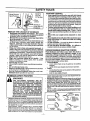
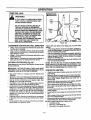
•
Hearing
Protection
_
Safety Hat
Snug
Fitting
Clothing
Eye Protection
Gloves
•
•
Safety
Shoes
Safety'Chaps
•
•
Figure t
•
KNOW YOUR SAW
•
Read your operator's manual carefully until you
completely understand and can follow all safety rules,
precautions, and operating instructions before attempting to operate the unit.
• Restrict the use of your saw to adult users who understand and can follow safety rules, precautions,and
operating instructionsfound in this manual
PLAN AHEAD
°
Wear protective gear. Figure 1. Always use stee/toed safety footwear with non-slip soles; snug-f_ting
clothing; heavy-duty, non-slip gloves; eye protection
such as non-fogging, vented goggles or face screen; an
approved safety hard hat; and sound barriers---_r
plugs or mufflers to protectyour hearing. Regular users
should have hearing checked regu/ady as chain saw
noise can damage hearing.
when
engineofisyour
running.
Keep the
all parts
body away from the chain
Keep children, bystanders, and animals a minimum
of 30 feet (10 Meters) away from the workarea. Do
not aliow other people or animals to be near the chain
saw when startingor operating the chain saw.
i
Do not handle or operate a chain sawwhen you are
fatigued, ill, or upset, or if you have taken alcohol,
drugs, or medication. You must be in good physical
conditionand mentallyalert Chain saw work is strenuous If you haveany condition that mightbe aggravated
by strenuouswork, check with yourdoctorbefore operating a chainsaw
Do not attempt to use your chain saw during bad
weather conditions such as strongwind. rain,snow,ice,
etc, or at night.
Carefully plan your sawing operation in advance.
Do notstart cutting untilyou have a c/ear wo_ area, secure footing,and, if you are fellingtrees, a planneo re" _'eat path.
Do not operate a chain saw that is damaged,
improperly adjusted, or not completely and
securely
assembled.
Always replace the
handguard immediately if it becomes damaged,
broken, or is other wise removed.
Keep the handles dry, clean, and free of oil or fuel
mixture.
W'dhthe engine stopped, hand carry the chain saw
with the muffler away from your body, and the guide
bar and chain to the rear, preferably coverea with a
scabbard,
HANDLE FUEL WITH CAUTION
•
Eliminate all sources of sparks or flames in the areas where fuel is mixed, poured, or stored. There •
should be no smoking, open flames, or work that could
cause sparks Allow engine to coo! before refueling.
• Mixand pour fuel in an outdoorarea on bare ground;
storefuel in a coot,dry, well ventilated place; and use an
approved, marked container for all fuel purposes
Wipe up all fuel spills before starting saw.
:, Move at least 10 feet (3 meters) from the tueling site
before starting the engine.
• Do not smoke while handling fuel or white operating the saw.
- Turn the engine off and let your saw cool in a noncombustible area, not on dry leaves, straw, paper, etc.
Slowly remove fuel cap and refuel unit.
• Store the unit and fuel in an areawhere fuelvapors cannot reach sparks or open flames from water heaters,
electric motors or switches, furnaces, etc.
I
......
SAFETY NOTICE
F-xposure
to vibra_ons
throughprolongeduseofgasolinepoweredhandtoolscouldcausebloodvesselor nervedamageinthefinge_,
hands,and wdstsofpeopleproneto circula_ondisordersor abnormalswellings.Prolongeduse incoldweatherhasbeen ,nKeam
bloodvessefdamagein
otherwbehealthypeople.Ifsymptomsoccursuch
asnumbness=
pain,lossofstrength, changeinskinco|_or
texture,or lossoffeelingin thefingers,handsor wrists,discontinue
theuseof_ unitandseek medicalattention_ ante-wt_rauon
system
.......
does notguaranteetheavoidance ofthese problems Userswhooperatepowertoolson a continualand regularbasismust
lmontlor closelytheirphys=cat
conditionand theconditionofth=sunit
j
I
_
FOR
SYMBOL
IT MEANS
- THIS
AT£ENTION!!!
LOOK
POINT
OUT
'MPORT_NT
SAFETY
BECOME
ALERT!!!
YOUR SAFETY
TO
-2-
IS PRECAUTIONS"
INVOLVED.
t
SAFETY RULES
OPERATE YOUR SAW SAFELY
•
•
Do not operate a chain saw with one hand. Serious
injuryto the operator, helpers, bystanders or any combination of these persons may resultfrom one-handed
operation. A chain saw is intendedfor two-handed use.
Operate the chain saw only in well-ventilated outdoor areas.
specificallytrained
do so.
Do not operate sawto from
a ladder or in a tree, unless
Position all parts of your body to the left of cut and
away from the chain when the engine is running.
• Cut wood only. Do not use your saw to pry or shove
away limbs, roots, or other objects.
• Make sure the chain will not make contact with any
object while starting the engine. Never try tostad the
saw when the guide bar is in a cut or kerr.
• Use extreme caution when cuffing small size brush
and saplings. Slender matedal can catch the chain
•and be whipped toward you or pull you off baJance.
- Be alert for springback when cuttinga limbthat is under tension so you will not be struck by IP_ limb or saw
when the tension in the wood fibers is released.
• Do not put pressure on the saw at the end of a cut.
Applying pressure can cause you to lose controlwhen
the cut is completed.
• Stop the engine before setting the saw down.
- Keep fuel and oil caps, screws, and fasteners securely tightened.
MAINTAIN
ORDER
*
.
•
•
,,
IA
,
,
KICKBACK-
KICKBACK
Have all chain saw service performed by your Sears
Service Center with the exception ofthe itemslisted in
the mainter_ncesection of thismanual. Forexample, if
improper tools are used to remove or hold the flywheel
when servicing the dutch, structural damage to the flywheel can occur and cause the flywheel to burst.
Make certain the chain stops moving when the
throttle trigger is released. For correction, refer to
"Carburetor Adjustments."
Stop the saw if the chain strikes a foreign objec'L
Inspect unitand repair or replace parts as necessary.
Disconnect the spark plug I_lore performing any
maintenance except for carburetor adjustments.
Never modify yoursaw in any way. Use only attachments supplied or'specificaJlyrecommended by the
manufacturer,
TRANSPORTING
:
*
°
•
.
GUARD AGAINST'
YOUR SAW IN GOOD WORKING
AND STORAGE
Stop the unit before transporting.
Allow engine to cool, cover theguide bar and chain, and
secure the unit before stodng or transporting in a vehicle.
Empty fuel tank before storing ortransporting the unit.
Use up any fuel left inthe carburetor by startingthe engine and letting the engine run until _ st.ops.
Store un_ and fuet in an area where lueI vapors cannot
reach sparks or open flames from water heaters, electric motors or switches, furnaces, etc.
Store unitsothe chaincannot accidentallycause injury.
Store the unit out of the reach of children.
IH,I
,,,, iii
i
i i
I,,II,H,,II,I
ii
i
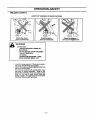
Kickback is a dangerous reaction that can lead to serious injury.
.....
.ll
......H.i
WARNING
Kickback
Path
KICKBACK CAN OCCUR WHEN THE
MOVING
CHAIN
CONTACTS
AN
OBJECT AT THE UPPER PORTION OF
THE TIP OF THE GUIDE BAR OR WHEN
THE WOOD CLOSES IN AND PINCHES
THE CHAIN IN THE CUT. CONTACT AT
THE UPPER PORTION OF THE TIP OF
THE GUIDE BAR CAN CAUSE THE
CHAIN TO DIG INTO THE OBJECT,
WHICH STOPS THE CHAIN FOR AN
INSTANT. THE RESULT IS A LIGHTNING
FAST, REVERSE REACTION WHICH
KICKS THE GUIDE BAR UP AND BACK
TOWARD• THE OPERATOR.
IF THE
CHAIN IS PINCHED ALONG THE TOP
OF THE GUIDE BAR, THE GUIDE BAR
CAN BE DRIVEN RAPIDLY BACK
TOWARD THE OPERATOR. EITHER OF
THESE REACTIONS CAN CAUSE LOSS
OF SAW CONTROL
WHICH CAN
RESULT IN SERIOUS INJURY. DO NOT
RELY ONLY ON THE SAFETY DEVICES
PROVIDED WITH YOUR SAW. AS A
CHAIN SAW USER, YOU MUST TAKE
SPECIAL SAFETY PRECAUTIONS TO
HELP KEEP YOUR CUTTING JOBS
FREE FROM ACCIDENT OR INJURY.
........
Rgure 2
Avoid
Obstructions
Clear The
Working Area
,,,,,,
Figure 3
-3-
i,i
ii
iii iii
i
HI
I
IIII
I
mlllr
SAFETY RULES
i,ll
MAINTAIN
CONTROL
4
Keep a good, firm grip on the saw with both hands
when the engine is running and don't let go. Figure
4. A firmgrip can neutralizekickbackand helpyou maintain controlofthe saw. Keep thefingers ofyourleft hand
encirclingand your leftthumb underthe fronthandlebar.
Keep your right handcompletelyaround the rear handle
whetheryou are righthanded or lefthanded. Keep your
left arm straightwiththe elbow locked.
• Position your left hand on the front handlebar so it
is in a straight line with your right hand on the rear
handle when making bucking cuts. Figure4. Never
reverse right and left hand positionsfor any typeof cut-
iNev
Rvee
1 sno
Hand Positions
The Left
Of The Saw
Elbow
Locked
•
Under Side Of
Handlebar
\
Figure 4
REDUCE THE CHANCE OF KICKBACK
•
•
•
•
•
_,
•
•
•
•
Recognize that kickback can happen. With a basic
understandingof kickback, you cen reducethe element
of surprise which contributes to accidents.
Never let the moving chain contact any object at the
tip of the guide bar. Figure 2.
Keep the working area free from obstructions such
as other trees, branches, rocks, fences, stumps, etc.
Figure 3. Eliminate or avoid any obstructionthat your
chain could hit while you are cuttingthrougha particular
log or branch.
Keep your chain sharp and properly tensioned. A
loose or dull chain can increase the chance of kickback
to occur. Follow manufacturer'schain sharpening and
maintenance instructions. Check tension at regufarinterva{s with the engine stopped, never with the engine
running. Make sure the bar clamp nuts are securely
tightened after tensioning the chain.
Begin and continue cutting at full throttle. If the
chain is moving at a slower speed, there is greater
chance for kickback to occur.
Cut one log at a time.
Use extreme caution when re-entering a previous
cut.
Do not attempt plunge cuts.
Watchforshiftinglogsorotherforoesthatcouldclose
a cut and pinch or fall into chain.
Use the Reduced-Kickback Guide Bar and LowKickback Chain specified for your saw.
,
KICKBACK
SAFETY
I&No
Hi
i
Jw, i
•
•
_d
with your weight evenly balanced on both
feet.
Stand slighUyto the left side of the sawto keepyour
body from being in a direct line with the cutting
chain. Figure 4.
Do not overreach. You could be drawn orthrown off
balance and lose controlof the saw.
Do not cut above shoulder height, it is difficultto
maintain control ofsaw above shoulder heighL
UNDERSTANDING
REACTIVE
FORCES
Pinch-Kickback and Pull-In occur when the chain is
suddenly stopped by being pinched, ¢a ught_ or by
contacting a tore_n object in the wood. Troisszopp_ng
ofthe chainresults in a reverea] of the chain force used to
cutwood and causes thesawto move in the oppositedirection of the chain rotation. E[ther reaction can resultin loss
of control and possibleserious injury.
• Pinch.Kickback
occurswhen chain on top of guide bar is suddenty
stopped.
rapidlydfivessawstraightbacktowardoperator.
• Puli-ln
OCcurswhen thechain on the bottom ofthe guide bar
is suddenly stopped.
pulls the saw rapidlyforward.
,,,,,,,, i
H,,,I,H
•
•
i ,, ,i
H
,,,
sampleofchainsawsbelow3.8 cubicinchdisplacement
specifiedin ANSI B175.1-1991,
Handguard,designedtoreducethechanceofyourleft hand
contacting
"{hechainifyour handsli.pcOffthe_ro_ hand!elo_r.
Positionof front and rear handlebars, oestgneO
w_na=stahoebetweenhandlesand =in-line with each other, i ne
spreadand =in4ine"positionof the handsprovided bythis designworktogethertogivebalanceand resistar_ce
in.p?.ntro.I,ling the pivotofthe sawbacktowardthe operazor_ lac_acK
OCCURS.
•sawsas set bythe American Naliot_
Standaras _,
B TS+l-199........
..,
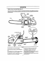
Reduced-Kickback G uide Bar,designedwitha smallradius
tip which reducesthe size of the Idckback danger zone onthe
Figure5.
•
FEATURES
THE FOLLOWING FEATURES ARE INCLUDED ON YOUR SAW TO HELP REDUCE
THE HAZARD OF KICKBACK; HOWEVER,
SUCH FEATURES WILL NOT TOTALLY
ELIMINATE THIS DANGEROUS REACTION.
AS A CHAIN SAW USER, DO NOT RELY
ONLY ON SAFETY DEVICES. YOU MUST
FOLLOW ALL SAFETY PRECAUTIONS,
INSTRUCTIONS, AND MAINTENANCE IN
THIS MANUAL TO HELP AVOID KICKBACK
AND OTHER FORCES WHICH CAN RESULT
IN SERIOUS INJURY.
guidebartip.
•
Cor_er_
•
_educe_ _c_
I_us
A,-_ _
T_P
Syra met_i_f Guide Bar
|_tO
AReduced-KickbackGuideBarisone
whichhasbeen demonstratedto significantly reducethe number and seriousness of kickbacks whentested in accordance
with ANSI B175.1 ;*-1991
Low-Kickback
Chain, designed
with a contoured depth
gauge and guard link which deflect kickback force and allow
wood to gradually
ride into the cutter. Figure 5. Low-K-Jckback
Chain is chain which has met £Jcl4_backperformance require*
ments of ANSI B175.1-1991
when tested on a representative
-4-
Syr_f_t
Gui_e_ar
_
.,
"
P_d_usT=#
1_€_
Figure 5
p_ettt_J
Cg_et
Wood
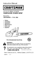
CONGRATULATIONS
on your
purchase of a Sears
Craftsman Gasoline Chain Saw. It has been designed, engineered and manufactured to give you the best possible
dependabilityand performance.
Should you experience any prob2ems you cannot easily
remedy, please contact your nearest Sears Service CentedDepartment Sears has competent, wel! trained technicians and the proper tools to service or repair this unit.
Please read and retain this manual. The instructions w_l
enable you to assemble and maintain your unit pmpedy.
Always observethe =SAFETY RULES."
PRODUCT
SPECIFICATIONS
GUIDE BAR: ..............
18_ (45.7cm}
CHAIN: ..................
Low Profile 3/8"
DISPLACEMENT:
.........
2-cycle/dr Cooled
FUEL/OIL MIX RATIO: .....
40:1 (3.2oz oil per gallon gas)
OILER: ..................
Automatic, 10.4oz. Tank
IGNITION: ................
Solid State
(Air gap .010"-.014")
IGNITION TIMING:
........
358.356242
)ATE OF PURCHASE:
•
•
•
SPARK PLUG GAP: ........
025" (.65ram)
MUFFLER: ...............
Spark Atre_ng Screen
ENGINE RPM: ............
12,300-13,200 RPM Maximum
SPECIAL NOTICE
AGREEMENT
A Sears MaintenanceAgreement is available on this product, Contact your nearest Sears Store for details.
CUSTOMER
Fixed
Champion CJ-TY
NUMBER WILL BE FOUND
YOU SHOULD RECORD BOTH SERIAL NUMBER
AND DATE OF PURCHASE AND KEEP IN A SAFE
PLACE FOR FUTURE REFERENCE.
MAINTENANCE
Non-Adjustable,
Autoi_te2974
_ERIAL NUMBER:
"HE MODEL AND SERI_
ON THE PRODUCT.
2.5 Cubic Inches (40cc)
ENGINE: .................
SPARK PLUG TYPE: ......
MODEL NUMBER:
Pitch
Chrome Cutters
RESPONSIBILITIES
Read and observe the safety rules.
Follow a regular schedule in maintaining, caring for,
and using your uniL
Follow the instructions under =Customer Responsibilities"and"Storage" sections of this Operator's Manual.
FULL 1 YEAR WARRANTY
Yoursaw is equipped withatemperaturelimltingmuffler
end spark arresting screen which meets the
requirementsof CaliforniaCodes4442and 4443.AIIU.S.
forest land and the states of Califom_ Idaho, Maine,
Minnesota,New Jersey,Washington,and Oregonrequire
many internal combustionenginesto be equippedwith a
sparkarre.._orscreen bylaw.
ifyou operatea chain sawin a stateorlocalewhere such
regulations exist, you are legally responsible for
maintaining the operating condition of these parts.
Failure to do so is s violation of the law. Refer to the
Spark
Arrestor
section
under
,Customer
Responsibilities"for maintenance,
MANL_FA_"tlJRB)UND_q ONE OR _ORS OFTHE FOt/.OW;NG PA_:
OTHER US. AND FOrtH
PATENTSPEP,_NG.
4,940X_.
ON GAS CHAIN SAW
Fo rune year from the date of purchase, when this Craftsman Gas-Powered Chain Saw is maintained, lubricated, and
tuned up according te the operator's manual, Sears will repair,free of charge, any defect in material or workmanship.
This warranty excludesthe bar, chain, spark plug, and air fitter,which are expendable parts and become worn during
nomla] use,
If this Gas Chain Saw is used for commercial purposes/this warranty applies for 30 days from the date of purchese.
WARRANTY SERVICE IS AVAILABLE BY RETURNING THIS CHAIN SAW TO THE NEAREST SEARS SERVICE
CENTER IN THE UNITED STATES.
This warranty gives you specific legal rights, and you may also have other rights which vary from state to state.
SEARS, ROEBUCK AND CO,, DEPT. 817WA, HOFFMAN ESTATES, IL 60179
-5-
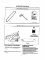
HARDWARE CONTENTS
m
Parts bag contents not shown full size
I
Chain
i_r Tool
Operator's Manual
Fuel/Oii Mix
(Bar Oil not included)
Purchase Craftsman Bar
and Chain Oil Separately
Engine
Gukie Bar.
TOOLS REQUIRED FOR ASSEMBLY
TO REMOVE CHAIN SAW
FROM CARTON
• Torque Wrench-referenc_ torque values are provided
throughout this manu_ for tighten)rig hardware,
Remove loose p_rts included with Chain Saw,
The saw and guide bar are packed in cardboa_ finer.
Grasp upper edge of cardboard 5ner with one nano.
and upper edge of carton with other nand. _lide out
cardboard liner containing s_w and guide bar.
• Set cardboard_En_f_bn
fl_t surface with tab flap on top.
•Release t,_b, lay siOefiat, and sSde outguide bar.
• Lay open other side of cardboard liner.
• Use cardboard finer as a work surface dudng assembly of saw.
• Bar Tool
NOTE: tt is norma_to hear the fuel filter rattle in _mempty
fuel tank.
,m, = ,
,,,i,ii
= ,
i,,,,,=
WARNING:
=
=r
=
i
J,,==
,,,,,
.............
!
IF THIS UNIT IS RECEWED ASSEMBLED,
REPEAT ALL STEPS IN THIS SECTION
TO BE SURE ASSEMBLY IS CORRECT
AND PROPERLY ADJUSTED FOR THE
OPERATOR.
HOW TO ASSEMBLE
,,,,=
I
|
|
i
!
YOUR
CHAIN SAW
BAR AND CHAIN
ASSEMBLY
\
(Fig. 6-13)
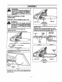
DANGER:
Clutch Drum
DO NOT START THE ENGINE WITHOUT
THE GUIDE BARAND CHAIN COMPLETELY
ASSEMBLED. OTHERWISE,, THE CLUTCH
CAN COME OFF AND SERIOUS INJURY,
i
CAN RESULT.
,
i
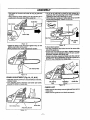
• Loosen and remove the 2 bar clamp nuts.
• Remove bar damp.
- Remove and throw away blue shippingspacer.
f
Guide Bar
Mounting Bolts
Guide Bar
Figure 8
• Carefully remove chain from bag. Hold chain with the
ddve links. Fig 9.
• Place chain over and behind the clutch drum. Fig 10.
* Frt bottomof drive links between teeth in sprocketnose.
• Rt chain drive linksinto top of guide bar. Rg 11.
Cutters
Depth
t
Gauge
Behind the
Clutch Drum
\1/
Drive
Links
=--.-
Rgure 10
Rgure 9
-=------- Bar Clamp
Bar Clamp Nuts
Figure 6
• Turn adjusting screw byhandcountemlockwise
justing pin just touches the stop.
until ad-
Nose
Guideear
Mounting Belts
Figure 11
Adjusting
Screw
Adjusting
Pin
Stop
Figure7
*Mount guide bar withslotted
end overbothguide bar
mounting bolts. Slide guide bar t_ehindctut_h drum' until
guide bar stops.
-7-
Guide Bar
....
..............
' bar
• Pull guide bar 'forward untit
chain is snug in guide
grooves.
• Now, install bar clamp making sure the adjusting pin is
positioned in the lower hole in the guide bar.
Guide Bar
• Lift uP""tipof g.ide bar 'iocheck for Sa'gi"release tip of
guide bar, then turn adjusting screw 1/4 turncJoc_ise.
Repeat thisstep untila sag does not exis_
• While liftingtip of guide bar, tighten bar clamp nutswith
the bar tool (provided).Torque 10-20 ft4bs.
Adjusting Screw
"_(_)_b._
Guide Bar
1/4 "rum
/
/
Lower Hole
Adjusting /
Pin ,,I /
Bar Clamp
Nuts
Figure 12
* Install bar clamp nuts and finger tighten only. Do not
tighten any further at this point.
Now proceed to the "Chain Adjustment" section.
Figure 15
To check chain tension:
* Use the screwdriverend of the bar too! to move chain
around the guide bar.
° Ifchain does not rotate,it istoo tight- slightlyloosen bar
clamp nuts and tum adjusting screw 1/4 turn counterclockwise. Retightenbar clamp nuts.
, If chain istoo loose,loosen bar clamp nuts;then, turnadjusting screw 1/4 turnc!ockwise. Liftup tip of guide butte
check for sag. Retightenbar clamp nuts°
l
Bar Clamp Nuts
Figure 13
CHAIN ADJUSTMENT
(Fig. 14, 15, &16)
• Roll chain around guide barto ensure kinks de not exist,
(rotates freely).
• "rum adjusting screw clockwise until chain just barely
touches the bottom of guide bar.
l
Bar Clamp
Nuts
Adjusting
Screw
Guide Bar
Figure 16
CHECK UST
• Make sure the bar clamp nuts ale tight andthere are no
loose parts.
• Make sure the guide bar and chain are secure.
Bar Clamp Nuts
Guide Bar
Adjusting Screw
Figure 14
-8-
i
=
_1 ,,,,ill
i
i,
,,
,_
i
i
,,,i,i
=
ii
IILIIII
IIII
ill
ILl
Ill, I,
.
OPERATION
,,
, ,=,,,
==
ill
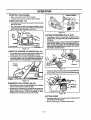
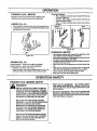
KNOW YOUR CHAIN SAW (See Fig. 17 )
READ THiS OPERATOR'S MANUAL AND SAFETY RULES BEFORE OPERATING YOUR CHAIN SAW, Compare the
i_lustrations
with yourunit to familiarize yourseffwith the location ofthe various controlsand adjustments, Save this manu_I
for future reference.
HANDGUARD
FRONT
HANDLE
STARTER
ROPEHANDLE
STOP
SWITCH
FUEL MiX
FILLCAP
STARTER
HOUSING
CYLINDER COVER
THROTTLE
REAR
HANDLE
•
THROTTLE
TRIGGER
ADJUSTING
SCREW
CHOKE/
FASTIDLE
CO_q3:{OL
_RCLAMP
NUTS
CHAINTI_VEL
DIRECTION
GUIDE BAR
BARCLAMP
t\1
...................Figur_
1_........................
The STOP SWITCH is used to stop the engine,
The THROTTLE TRIGGER controlsengine speed.
The STARTER ROPE HANDLE is used for starting the engine,
The GUIDE BAR is designedto carry the chain.
Thee C_IO_'E!F,_ST'IDLE CONTROL_ p_ovidi_sadder{oral
fuel to the engine when sta_t}ng a cold engine.
The BAF_CI_vl P NUTS are designedto hold the guide bar
after adjustments have been completed.
The THROTTLE LOCKOUT prevents the THROTTLE
TRIGGER from being squeezed accidentally,
The ADJUSTING SCREW is designedto tension the chain
around the guide bar,
The CUTTERS are designed to cut the wood,
-9-
_N
STOPPING
YOUR ENGINE
• Move stop switch to the "STOP" position.
o If engine does not stop, pull choke lever out fully.
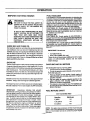
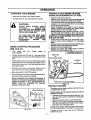
CHAIN OILER (Fig. 18 )
•
•
Yourchain saw will consume one tank of bar oil for each
tank of fuel used.
The chain oiler provides continuouslubricationto the
chain and guide bar. Be sure to fg] the bar oiltank when
you fill the fuel tank (Capacity = 6.5 fl.oz.).
a
Figure 20
CuI"rlNG TECHNIQUES
Oil Fill
Overcutting- begin on the top side of the log with the
bottomof the saw against the log; exert light pressure
downward.
•
Undercutting-begin on theunder side ofthe log withthe
top of the s_w against the Io9; exert light pressure up:.
ward. During undercutting,the saw will tend to pusn
backat you. Be prepared 1or this reaction and hold the
saw firmly to maintatn control.
\i
Bar
\!
Front Handle
.....................
THROI-rLE
Fuel CaD
Figure 18
TRIGGER
(Fig. 21 & 22 )
•
& LOCKOUT (Fig. 19 )
• Thethmttletdggercontrols enginespeed.Atidle, acentrifugat ctutch automatically disengages the chain.
• The throttte lockout prevents unintentional actuation of
the throttle tdgger. Also, the throttle lockout must be depressed before the throttle trigger can be depressed.
Throttle
Lo_out
:_
CHOKE/FAST
•
Figure 21
Pos_on the bottomofthe front saw fame against the log-
•
Duringcutting,keep the frontsaw frame against the log.
Figure 19
IDLE SPEED (Fig. 20 )
• The throttle and choke are a,utomaticallyset for starling
when the choke lever is pulled out fully.
• Squeezing the throttletrigger wilt retease the choke and
fast idle settings. If the throttle trigger is squeezed acc'_dently during starting, it will be necessary to reset
throttle advance by pulling choke lever out fulb'.
Front Saw Frame
Figure 22
CUTTING SPEED
•
•
- 10 -
Accelerate engine to full throttle before entering cut by
squeezing the throttle trigger.
Never cut with engine at partial throttle speed.
IIIIIIH
I
I
.
I
IIIIIIIIII
I
.--
I
IIII
I
I
II I
I
IIIHI
OPERATION
iiiiiiiii
i
i,,111
OPERATION
i
,
i
i
ii
IHI
III
IIII
IIIIIIIIIIIIII
USE/TIPS
Q
•
Cut woodonly. Do not cut metat; plastics; masonry;, nonwood building materials; etc.
, Stopthe saw ifthe chain strikes a foreign object. Inspect
the saw and repair or replace parts as necessary.
• Keep the chain cut of dirt and sand. Even a small
amount of dirt wilt quickty dull a chain and thus increase
the possibility of kickback.
To get the _eel" of usingyour saw before you begin a major
sawing opera, on, practice cutting a few small togs usingthe
followingtechnique:
• Accelerate engine to full throttle before entedng cut
by squeezing the throttle trigger.
t
I
I
,,
I
,,,,,,,,,,,,,,,
i
iiii i
iii ii
i
Begin cuttingw_ththe saw frame against the log.
Keep engine at fullthrottle during cuttingprocedure.
Allow the chain to cut for you; exert only light downward pressure. If you force the cut, damage to the
bar, chain, or engine can result.
Release thethrottle triggeras soonas the cutis completed, allowing the engine to idle. Ifyou run the unit
at futl throttle without cutting,unnecessarywear can
occurto the chain, bar, and engine.
To avoid losing control when completingthe cut, do
not put pressure on the saw dunngthe end of the cut.
Stop engine before settingunitdownafter operation.
OPERATION-SAFETY
i
i
i
,,
H
iii
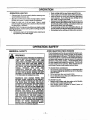
GENERAL SAFETY
i
i
i
AVOID REACTIVE
,,,,,,,L,,ii
WARNING
IF SAW BECOMES PINCHED OR HUNG IN A
LOG, DO NOT TRY TO FORCE IT OUT. YOU
CAN LOSE CONTROL OF THE SAW
RESULTING IN INJURY AND/OR DAMAGE
TO THE SAW. STOP THE SAW, DRIVE A
WEDGE OF PLASTIC OR WOOD INTO THE
CUT UNTIL THE SAW CAN BE REMOVED
EASILY. RESTART
THE
SAW
AND
CAREFULLY REENTER THE CUT. TO
AVOID KICKBACK AND CHAIN DAMAGE,
DO NOT USE A METAL WEDGE, DO NOT
ATTEMPT TO RESTART YOUR SAW WHEN
IT IS PINCHED OR HUNG IN A LOG.
KICKBACK
CAN OCCUR WHEN Tile
MOVING CHAIN CONTACTS AN OBJECT
AT THE UPPER PORTION OF THE TiP OF
THE GUIDE BAR OR WHEN THE WOOD
CLOSES IN AND PINCHES THE SAW CHAIN
IN THE CUT. CONTACT AT THE UPPER
PORTION OF THE TiP OF THE GUIDE BAR
CAN CAUSE THE CHAIN TO DIG INTO THE
OBJECT AND STOP 3"HE CHAIN FOR AN
INSTANT. THE RESULT IS A LIGHTNING
FAST, REVERSE REACTION WHICH KICKS
THE GUIDE BAR UP AND BACK TOWARD
THE OPERATOR. IF THE SAW CHAIN IS
PINCHED ALONG THE TOP OF THE GUIDE
BAR, THE GUIDE BAR CAN BE DRIVEN
RAPIDLY BACK TOWARD THE!OPERATOR.
EITHER OF THESE REACTIONS
CAN
CAUSE LOSS OF SAW CONTROL WHICH
CAN RESULT IN SERIOUS INJURY.
- 11 -
,,,,,,
,,,,,,,,,,,,,,,,,,,,
i
i
ii iiiiiiii
PINCH FORCES
Pinch-Kickbackand PulHn occur when the chain issuddenly stoppedby being pinched, caught, or by contacting aforeign object in the wood. This sudden stopping of
the chain results in a reversal of the chain force used to
cut wood and causes the saw to move in the opposite
direction of the chain rotation. Pinch-Kickback drives
the saw straight back toward the operator. PuU-tnpulls
the saw away from the operator. Eitherreaction can result in loss of control and possibly serious injury.
TO AVOID PINCH-KICKBACK:
* Be extremely aware of situationsor obstructionsthat
can cause rnatedal to pinch the top of or otherwise
stop the chain.
o Do not cut more than one log at a time.
. Donottwistthesawasthebariswithdrawnfrom
an
under-cutwhen bucking.
TO AVOID PULL-IN:
o Always begincuffing with the engine at full throttle
and the saw housing against wooo.
- Use wedges made of ptastic or wood, (never of
metal) to hold the cut open.
ii
ilull i
ii
i i
r
iiii
iii
I
iii
i
i
ii
i,iiiinll
iiil,,inll
i
OPERATION
,
i
i i
i i
,,,,,,,,,,
iiiiii
TREE FELLING
,,,111111111111_
ii
n iiiii,nll
i
.....
'Felling Direction .........
WARNING
IF THE TRUNK OR LIMBS ARE ROTTING,
THEY CAN FALL UNEXPECTEDLY AND
CAUSE SERIOUS INJURY.
Felling
Top
Notch
Cut
//°=
-".U_I="
AS YOU MAKE YOUR FELLING CUT, IF
THE SAW APPEARS TO BE BINDING,
THE TREE IS STARTING TO FALL IN THE
WRONG DIRECTION. IMMEDIATELY STOP
THE SAW AND USE A FELLING WEDGE
AND MAUL (HAMMER) TO FORCE TIlE
FELLING CUT OPEN. THE WEDGE WILL
HOLD THE FELLING CUT OPEN
.ALLOWING YOU TO REMOVE THE SAW.
KEEP EVERYONE AWAYFROM THE
"TREE IN ALL DIRECTIONS.
13ottom
BUttress
Root
Notch
Cut
Figure 23
DETERMINE
THE NATURAL FALL DIRECTION
•
Wind-A tree evenlybalanced willfall in the same direction the wind is blowing.
• Lean - Use a carpenter's level or plumb bob to determine if tree has a naturallean. A leaning tree willtend to
fall in direction of lean.
• Shape - A tree willtend to fail towards sidethatis more
heavily branched.
• Other Factors- Contacting or nearbytrees, buildings, or
wires can influence the direction the tree willfall.
CUTTING
PROCEDURE
(Fig. 23 )
After determining the Natura! Fall Direction,the tree should
be cul as foliows:
IMPORTANT: BEFORE FELLING A TREE, MAKE SURE
YOU HAVE AT LEAST 3 FELLING WEDGES AND A MAUL
(HAMMER) AVAILABLE FOR USE IF NEEDED.
,
•
•
•
•
-
Use some means to visually mark the Natural Fall
Direction.
Mark your notch cut on the Natural Fall Direction side of
the tree approximately 18-24 inches above the ground.
Cut top of the notch first at a 45 degree angle. Saw
through 1/3 of the width of the tree.
Cut bottom of the notch at a 45 degree angle until you
meet the top notchcut Remove notch of wood.
On the side of the tree oppositethe notch cut, make the
felling cut. The felling cut should be 2 inches above the
center point of the notch cut. Before the felling cut is
complete, use wedges to open the cut when necessary
to control the direction of the fall. Use wood or plastic
wedges, but neversteel or iron, to avoid idckback and
chain damage.
Cracking sounds, widening of the felling cut, movement
in the upper branches are all signs that the tree is ready
to fall.
As tree begins to fall, turn off saw, set it down, and move
quickly away from direction of fall.
if your chain saw binds in the felling cut, you have three options:
• If the wrong directionof fall is acceptS, le, c_ietully re:.
move the felling wedge, Cut deeper in me notchsioe ot
the tree untiltree startsto fall.
• If the wrong directionof falt is not ac.c.
eptable,.a_empt.to
use one or more felling wedges to mrce the tree in.me
original direction of fall Do so by ddving the weoges
deeper into the fellingcut,
• Keep everyone away from the tree in all directionsand
then seek professionalhelp!
NOTE: For trees less than 6 inches in diameter, make a
single felling cut on the side away from the direr."on of _1!.
Cut through untiltree begins to fall. Then turn o_s_.w,smn
down, and move quickly away from direction oTra_.
OPERATION
°
USE/TIPS
Clear the work area of debris where you can have secure footing.
* Make sure there is enough room forthetree to fall. Maim
taJn adistance of 21/2 tree lengths fromthe nearest person or other objects. Engine noise can crown out a
warning call.
• Remove dirt,stones, loose bark, nails,staples, and wire
from the tree where cuts are to be made.
° Plan to stand on the up-hil! side when Gutting on a slope.
- Plan a clear retreat path to the rear and diagonal tothe
line of fall.
, If unsure about which way a tree will fall, use the notch
cutting method.
• Large buttress roots should be removed prior to notch
cut.
, Use a wedge if there is any chance that the tree will not
fall in the desired direction.
, We recommendycu cut branches below shoulder height
before felling tree. (See Limbing and Pruning).
Be alert to signs that the tree is ready to fall:
• Crackingsounds.
• Widening of theie|lirtg'c'_:
• Movement in the upper branches..
- 22 -
ill, iiiii,1111
i
FELLING
SAFETY
iiii
.....................
DON'T PUT YOURSELF IN THESE POSITIONS
_ i
Check the wind-Don't cut down wind
Check the lean-Don_tcut on lean side
i,i
ill
WARNING
DO NOT CUT:
'-NEAR ELECTRICAL WIRES OR
BUILDINGS.
-IF YOU DO NOT KNOW THE DIRECTION OF _EE FALL
-AT NIGHT.
-DURING BAD WEATHER- RAIN,
SNOW, STRONG, WIND, EI'C.
*
Look for decay and rot. If the trunk is rotted, it
can snap and fatltowan_ the operator.
. Check for broken or dead branches which can
fall on you while cutting.
o Be extremely cautious with partially fallen trees
that may be poody supported.
When a tree
doesn't fall completely, set the saw aside and pull
down the tree with a cable winch, block and
. tackle, ortractor. To avoid injury', do notcutdown
a partially fallen tree with your saw.
- 13 -
i
i
i,,111
iiiiii
ii
i
ii,
iii ii
ii
i
iiiiiiiiiiiiiii i
i
i
OPERATION
Ill
BUCKING
Bucking is cutting a fallen tree t° the desired log size.
TYPES OF cuTrlNG
(Fig. 24 )
.
Ill
BUCKING USING A SUPPORT (Fig. 26 & 27 )
Anotherlogor a stand, suchas a sawhorse, may be usedas
supports when bucking.
. , .
Area A- Undercut 1/3 of the way througn me log.
- Finishwith an overcut.
• Area B- Overcut 1/3 of the waythrough the log.
- Finish with an undercut.
Overcutt_ng - begin on the top side of the log with the
bottom of the saw against the log; exert light pressure
downward.
Undercutting-begin on the underside of the log withthe
top of the saw against the log;exert light pressure up:.
ward. Dudng undercutting, the saw will tend to push
back at you. Be prepared for this reaction and hold the
saw firmtyto maintain control.
I
1_Cut
...........
F ure26
,=o=
i
c.,t
,
Figure 24
BUCKING
•
•
ON THE GROUND
(Fig. 25 )
Overcut with a 1/3 diameter cut.
Roll tog over and finish with an overcut.
Another Log
- - : ....
Figure 27
OPERATING
:
i
•
Figure 25
,=l.
=
i,
.HHI
L
=
I=
=
USE/TIPS
Cut only one log at a time.
.
_
Cut shattered wood very earefully. Sharp pieces or wooocould be flung toward the operator.
person to ho!d the log while outing and never held the
se a sawhorse
logwith
your leg to
or cut
foolsmall logs.
..... Never allow another
Do not cut in an area where logs, limps, ano rootsare
tangled such as in a blown down area. Dragthe togsinto
a clear area before cutting by pullingout exposed and
cleared
logs first.
"
nto. prevent the
Give specia!attention
to logs unaerstrai
saw from pinching. Make the first cut on the pressure
side to relieve the stress on the log.
.I
=
J= I
=
= H
OPERATION-SAFETY
BUCKING
•
Ig
SAFETY
Stay on uphill side of tree when cutting.
DO NOT STAND ON THE LOG BEING
CUT. ANY PORTION CAN ROLL CAUSING LOSS OF FOOTING AND CONTROL
NEVER TURN THE SAW UPSIDE DOWN
TO UNDERCUT,
THE SAW CANNOT BE
CONTROLLED
IN THIS POSITION.
Mair_ain Secure
-14 -
Footing.
=
=l ,,
i
,
,,,,i
=,,,,
===
_ =
=
,,,,,=
==
=
OPERATION
'PRUNING
AND LIMBING
Pruning Procedure
• First- Undercut1/3 of the waythrough the limbnear
the trunk of the tree.
• Second - Finish with an overcut farther out from the
trunk unti! the limb falls.
• Third - Cut the remaining stump flush near trunk of
the tree.
Pruning is removingbranches from a standingtree.
Limbing is removing branches from a felled tree.
LIMBING (Fig. 28 )
o Start at base of the felled tree and worktoward the top.
- Leave the larger limbsunderneath the felledtree to support the tree as you work.
Second
Pruning Cut
Third
Figure 29
OPERATING
USErrlPS
• Work slowly, keeping both hands firmly gripped on the
saw. Maintain secure footing and balance.
• Keepaclearworkarea.Frequentlyclearbranchesoutof
the way to avoid 1Tippingover them.
• Leave the larger limbsunderneaththefelledtreetosupport the tree as you work.
o Start at the base of the felled tree and work toward the
Figure 28
:PRUNING (Fig. 29 )
Small branches - smaller than width of guide.bar.
Large branches - larger than width of guidebar.
• Remove smal! limbs with one cut.
- Remove larger, supporting branches with the 1/3 -2/3
cutting techniques described in the bucking section.
i
i
,
±
top.
•
•
•
Keep the tree between you and the chain. Cut from the
side of the tree oppositethe branchyou are cutting.
Limit pruningto limbs shoulder height or below.
Keep out of the way of the falling limb.
......
,,,i
,
.....................
,,
==
,i
=
,,,,,,,
PRUNING AND LIMBING SAFETY
I
WARNING
NEVER CLIMB INTO A TREE TO UMB OR
PRUNE UNLESS SPECIFICALLY TRAINED
TO DO SO. DO NOT STAND ON LADDERS,
PLATFORMS, A LOG, ORIN ANY POSITION
WHICH CAN CAUSE YOU TO LOBE YOUR
BALANCE OR CONTROL OFTHE SAW.
Watch, out for springpoles.
•Use extreme caution
whencutting small size limbs. Slender matedal ma_,
catch thesaw chain and bewhipped towaro you or pull
yOUOffbalance.
Be alert for springback. Watch out for branches that
are bent or ur_derpressure as you are .cutti'ng
_ avoid
being struck by the branch orthe saw wnan me tenston
in the wood fibers is released.
BE ALERT FOR AND GUARD AGAINST
KICKBACK. DO NOT ALLOW THE MOVING
CHAIN TO CONTACT ANY OTHER
BRANCHES OR OBJECTS AT THE NOSE
OF THE GUIDE BAR WHEN LIMBING OR
PRUNING. ALLOWING SUCH CONTACT
CAN RESULT IN SERIOUS INJURY.
D O"NO_iF'tS"RAI_CRES'AR_
PEGFIER
THAN YOUR SHOULDER. GET A PROFESSIONAL TO DO THE JOB. THIS MAY RESULT IN SERIOUS INJURY.
-15-
J,,,i,
i
i
i
i
,,
i
ii
illll,i
............................
""
OPERATION
ii
BEFORE
STARTING
iiiiiiiii
i
lllllllllllllllllll
ii i
ii
i
iiiii
FUEL STABILiTPR
ENGINE:
WARNING:
BE SURE TO READ THE FUEL SAFETY INFORMATION IN THE SAFETY RULES SECTION ON PAGE 2 OF THIS MANUAL BEFORE YOU BEGIN.
IF YOU DO NOT UNDERSTAND THE FUEL
SAFETY SECTION DO NOT ATTEMPT TO
FUEL YOUR UNIT; SEEK HELP FROM
SOMEONE THAT DOES UNDERSTAND THE
FUEL SAFETY SECTION OR CALL THE
CUSTOMER ASSISTANCE HOTUNE AT
1_800-235-5878.
GUIDE BAR AND CHAIN OIL
For maximum guide bar and chain life, we recommend you
use Craftsman chain saw bar oil. If Craftsman bar oil is not
avaJlable, you may use a goodgrade SAE30 oiluntil you are
able to obtain Craftsman brand. The oil output is automaticallymetered during operation. Your saw willuse one tank of
baroil for every tank of fuel mix. Always fill the bar oil tank
when you fill the fuel tank.
Fuel stabilizer isan acceptable alternative in minimizing the
formationof fuel gum depositsdudngstorage.AddstabilLzer
to gasoline in fuel tank or storage container.Always follow
the fuel mix ratio found on the stabilizer container. Run
engine at least 5 minutesafteradding stabilizerto allow the
stabilizer to reach the carburetor.You do not have to drain
the fuel tank for storage if you are usingfuel stabilizer.
CRAFTSMAN 40:1 2-cycle engine oil (AIR-COOLED) is
speciallyblended with fuel stabilizers.Ifyou do not use this
Sears oil, you can add a fuel stabilizer (such as Craftsman
No. 33500) to your fue! tank,
2-CYCLE OIL:
CRAFTSMAN 40:1 2-cycle engine oil (AIR-COOLED)
stronglyrecommended.This oilisspe_a|ly blendedwithfue|
stabilizersfor increasedfuel stabilk'y(extendsfuel rffeupto 5
times longer) and reduced smoke.
If CRAFTSMAN 40:1 2.cycle engine oil (AIR-COOLED) is
not available, use a good quality 40:1 2-cycle engine oil
(AIR-COOLED) engine oil thathas a recommendedfuel mix .
ratio40:1.
IMPORTAN'13 Do not use:
• AUTOMOTIVE OIL
• BOAT OILS (NMMA, BIA. etc.)
These oils do not have proper additives for 40:1 2-cycle
engine oil (AIR-COOLED) engines and can cause
engine damage.
GASOLINE
The two-cycle engine on thisproductrequiresa fuel mixture
of regular unleaded gasolineand a high quality40:1 2.-cycle
engine oil (AIR-COOLED) for lubricationof the bearings and
other moving parts. The correctfueVo_ mixture is40:1 (see
Fuel Mixture Chart). Too t_le oil or the incorrect oiltype will
cause poor performance and may causethe engine to overheat and seize.
Gasoline and,oil must be premixed in a clean approved fuel
container. Always use fresh regular unleaded gasoline.
Thisengine hasbeen certified to operateon unleaded gasoline and Craftsman 40:1 2-cycle engine oil(AIR-COOLED).
IMPORTANT:
Experience indicates that alcohol
blended fuels caIled gasohol (or using ethanol or methanol) can attract moisture, which leads to oiVgas separation and formation of acids during storage. Acidic gas
can damage the fuel system of an engine while in storage. To avoid engine problems, the fuel system should
be emptied before storage for 30 days or longer. Drain
the gas tank, then run the fuel out of the carburetor and
fuel lines by starting the engine and letting it run until it
stops. Use fresh fuel next season_. See STORAGE
instructions for additional information. Never use engine
or carburetor cleaner products in the fuel tank or permanent damage may occur.
GASOLINE
AND OIL MIXTURE
MIX GASOLINE AND OIL AS FOLLOWS:
• Consult cha.,tfor correctquarr_ies.
• Do not mix gasoline and oil directly in the fuel tank.
FOR ONE GALLON:
• Pour 3.2 ounces of high quality, 2-cycle engine oil
(AIR-COOLED) into an empty, approved one gallon
gasoline container.
• Add one gallon of regular unleaded gasoline to the
gallon container, then securely replace the cap,
Shake the container momentarily.
o The mixture is now readyfor use. Fuel stabi{izercan
be added at this time if desired;follow mixing ins'mJCtions on the label.
FUEL MIXTURE CHART
40:1 Fuel:Oil Mix Ratio
Oil (1'1.o_}
1 gallon
3.2
1.25 gallons
4,0
2.5 gallons
8.0
NOTE: One gallon fuel containers will hold more than one
gallon. Iftoo much gasoline is in the container,the resulting
gas-to-oil fuel mixture wilt not be correct for proper engine
- 16 operation.
OPERATION
,,ill
I
STOPPING
YOUR
II
I
IIIIII I
II
IIm,,,ll
ENGINE
•
Move the stop switch to,the =STOP" position.
•
If engine does not stop, pull choke lever out fully.
ENGINE
•
•
WARNING:
ALWAYS WEAR GLOVES; SAFETY
FOOTWEAR;
SNUG-FITTING
CLOTHING; AND EYE, HEARING, AND
HEAD PROTECTION DEVICES WHEN
OPERATING A CHAIN SAW.
•
•
THE CHAIN MUST NOT MOVE WHEN
THE ENGINE RUNS AT IDLE SPEED.
REFER
TO
THE
=CARBURETOR
ADJUSTMENTS "
SECTION
FOR
CORRECTION.
•
•
.........................
AFTER
RUNNING
Keep the choke lever pulled out.
W'rththe saw on the ground, grabfront handle with left
hand and place rightfoot on mnsiaeor rear handle.
Pullstarterrope handlewith yourrighthand until engine
attempts to run, then push choke lever in and continue
to pull rope untilengine starts.
Above 40 degrees, allow engine to run for approximately 5 seconds, then squeeze and release throttle
lock and trigger to allow the engine to idle.
Below 40 degrees, allow engineto warm up 1-2 minuteswith choke about half-way in.Then, squeeze and
release throttle lock and triggerto allow engine to idle.
•
Pull the choke control fully out to set fast idle. Then,
push the choke;control completely in to- disengage
choke.
• Withsaw on the ground,grab fronthandle with left hand
and place nght foot on inside of rear handle.
• Pullstarter rope untilengine starts.
- Squeeze and release the throttle trigger to release
throttle lock, allowing engine to !die.
,
Fuel engine with 40:1 2-cycle engine oil
(AIR-COOLED).
RU bar oil tank with STS bar oil Your saw will use
approximatety one tank of bar oil for each tank of fuel
mix.
i
Set chain saw firmly on the ground. Make sure the
chain is free to turn without contacting any object.
-
Move stop switch to the STOP position.
•
Pull out fuily the blue choke lever to automaticallyset
choke and throttle advance for starting.
STARTING POSmON
I
Right Hand
on
Starter Rope H_ndte
When pulling the starter rope, do not use the full extent
of the rope as this can cause the rope to break. Do not
let the starter snap back - hold the handle and let the
rope rewind slowly.
•
OUT OF FUEL
STARTING A WARM ENGINE THAT HAS NOT
RUN OUT OF FUEL
BASIC STARTING PROCEDURE
(Fig. 30 & 31 )
o
I
STARTING A COLD ENGINE OR WARM
l ,.,
DO NOT SQUEEZE THE THROTTLE TRIGGER. IF
THROTTLE TRIGGER IS SQUEEZED ACClDENTLY
DURING STARTING, IT WILL BE NECESSARY TO
RESET THROTTLE
ADVANCE
BY PULLING
CHOKE LEVER BACK OUT.
Front Handle
Right Foot through Rear Handle
Figure 31
DIFRCULT
STARTING
The engine may be flooded with too much fuel if it has
not started after 20 pulls.
Choke Positions
Flooded engines can be cleared of excess fuel with the
followingprocedure:
• Pull choke contro!fully out to set the fast idle. Then
push the choke control completely in to disengage
the choke.
• Verifythat the stop switch is in the ON position.
• W'rthsaw on the ground, grab front handle with left
hand and place right foot on inside of rear handle.
, PuJ!sta_er rope,until engine starts.
Starting could require pulling the starter rope handle
many times depending o n how badlythe unit isflooded.
i
Figure 30
If engine still fails to start, refer to the "TROUBLE
SHOOTING" chart.
-t7
-
i,,ml
,i,
,,,,,,,
CUSTOMER
...................
MAINTENANCE
ii
,,,,,,,,,,,,,,,,
i,i
iii
H
I
,,
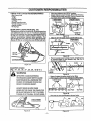
,,,,,lllllllilllllll
SCHEDULE
Fill in dates as you complete regular service
Before
Use
Every
25 hrs
Every
Season
Service Dates
p,,
.......
Check
for
D maqed
orWo ,
Every
5 hrs
After
Use
Clean Unit and Labels ............................
J
...................
,.."
Check for Loose Fasteners and Parts
f
Check Chain Sharpness
P"
!Guide_Bar Maintenance
i
RESPONSIBILITIES
ps
,H
p,,
•
i
p,.
H,i Hi
p,,
Check Clutch Drum Sprocket
P"
,
i,ii
Clean Air Filter
iHi
p,,
....
i
i
, ,l
i
N
SePAce,_eplac'_ _ParkPlug
liH
Clean/Inspect:SparkArrestor Screen and InspectMuffler
Ill
p,,
II
:Check Guide Bar Lube
ii
Hi
ps
v_
,
Filter in Fuel Tank
GENERAL
p,,
BEFORE EACH USE
RECOMMENDATIONS
The warranty on this unit does not cover items that have
been subjected to operator abuse or negligence, To receive full value from the warranty,the operator mustmaintain unit as instructedin this manual.
CHECK FOR DAMAGED/WORN
Some adjustments will need to be made periodicallyto
properly maintain your unit.
All adjustments in the "Service and Adjustments" section
of this manual should be checked at least once each season.
• Once a year, replace the spark plug, replace air filter element and check guide bar and chain for wear. A new
spark plug and a clean/new air fitter element assures
proper air-fuel mixture and helps your engine run better
and last longer.
o Follow the;maintenance schedule in this manual.
LUBRICATION
CHART (Fig. 32 )
WARNING
O
DISCONNECT THE SPARK PLUG BEFORE
PERFORMING
MAINTENANCE
EXCEPT
FOR CARBURETOR ADJUSTMENTS,
BAR OIL
FILL CAP
INSPECT THE ENTIRE UNIT.
REPLACE
DAMAGED PARTS. CHECK FOR FUEL
LEAKS AND MAKE SURE ALL FASTENERS
ARE IN PLACE AND SECURELY FASTENED.
,,,i,,,
,
CLEAN UNIT AND LABELS
• Clean the unit using a damp cloth with a mild detergent.
• Wllseoff the unit with a clean dry cloth.
PARTS
The following damaged/worn parts should be referred to
your Sears Service Center
NOTE: It is normal for a small amount of oilto appear un*
der the saw after engine stops, Do not confuse thisw_ a
leaking oil tank.
• On/Stop Switch- ensure on/stop switchfunctionsprop
edy by moving the switch to the =Stop"position and assure that engine stops,then restartyourengine and continue.
• Fuel Tank - discontinue use of chain saw if fuel tank
shows signs of damage or leaks.
.
.
° Oil Tank- discontinue use of chain saw if oHtank snows
signs of damage or leaks.
• Chain Catcher - replace chain catcher if bent, cut, or
damaged in any way.
Figure 32
;_°_raftsman
- 18 -
chain saw bar oil.
cusTOMER
,,,,,,,,
RESIPONSIBiLITIES
i
CHECK FOR LOOSE
• Bar Clamp Nuts
• Chain
• Muffler
• Cylinder Shield
• Air Filter
,,,,i, ii
i
FASTENERS/PARTS
•
•
•
i
.............
i
Move stop switch to the _STOF_ position.
Adjust chain for proper tension. (See Chain Tension).
Positionthe file holder level (90 =) sothat it rests on the
......
top edges of the cutter and depth gauge.
lsIoEWEW
J
pRO view]
File HoTder
. Clutch Drum/Sprocket
Throttle Trigger/Lockout
• Handle Screws
- AV Springs
File
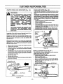
GUIDE BAR LUBRICATION
(Fig. 33 )
For maximum guide bar and chainlife,we recommendyou
use Craffsrr_n chain saw bar oil. if Craftsman chain saw
bar oil is not available, you may use a good grade SAE 30
oil until your are able to obtain Craftsman brand. The oil
output is automatically metered during operation. Your
saw will use one tank of bar oilfor every tank of fuel mix..
Always fill the bar oil tank when you fill the fuel tank.
&Chain
Culler,, DepthGau_
Figure 35
All,in the 30 ° file holder marks parallel with the bar.
.,
30'_ : File ..........
"File Holdei:Ma_s[_
I TOP VIEW J
:
Bar Oil
•
Figure 36
File from inside toward outsideof cutter, straightacross
on forward stroke in one direction only. Use 2 or :3
strokes per cutting edge.
Figure 33
SHARPEN
CHAIN
(Fig. 34,35,36,37,38,39,40
_
& 41 )
WARNING
Figure 37
outtersthe same
IMPROPER CHAIN SHARPENING
TECHNIQUES AND/OR DEPTH GAUGE
MAINTENANCE WILL INCREASE THE
CHANCE OF KICKBACK WHICH CAN
RESULT IN SERIOUS INJURY.
ALWAYS WEAR GLOVES WHEN
HANDLING THE CHAIN. THE CHAIN CAN
BE SHARP ENOUGH TO CUT YOU EVEN
THOUGH IT IS TOO DULL TO CUT WOOD.
Figure 38
,File
IlUlIIII
I
IIIII
III
cha!n to meet specifications shown below.
,
85 °
.i,....I
Figure 34
Figure 39
-19--
,,f
,
, ii
,,
i
CUSTOMER
,i
•
•
ii
iii
,
i
,,,,,,,,,,,,,,,,,,iii
,,,,i
RESPONSIBILITIES
..........................................................
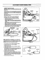
Place depth gauge tool over each cutter depth gauge.
F_edepthgaugewithaflatfileuntilitislevelwiththetop
of the depthgauge tool
"
....................
•
*
iiiiii
Move stop switch to the "STOP" position.
Cleanallsawdustandanyotherdebrisfro,mtheguide
bar groove and guide bar oil lubricationhole.
Lubricateguide bar nose sprocketafter each use,
Burdngof bar railsis a normal process ofguldebar rail
wear, Remove these burrs by filingguide bar railside
edges square with a flat file.
Remove Sawdust
From Guide Bar Groove
Rgure 40
Maintainroundedfront comer of depth gauge with a fiat
file. The very topof the depthgauge shouldbe fiat with
the front half rounded off with a fiat file.
Hook
o
HookAn<e
OffCornel
Figure 43
0
Right Way
CHECK VIBRATION
Wrong Way--
MOUNTS (Fig. 44 )
Yourchainsaw is designedwith an Anti-'Vqbration
(A_ sys:
tern that decreases the amount of vibration transferreo
from the main body to the handles.
Figure 41
CHECK GUIDE BAR (Fig. 42 & 43 )
A wom guide bar willdamage the chain and make cutting
o.micult.Check the conditionofthe guide bar each time the
Cllain is sharpened. Conditionsinclude:
• Chain saw cuts to one side or at an angle.
• Chain saw has to be forced through the cut.
• Inadequate supply of oil to the bar and chain.
if replacement is necessary, use only the replacement reduced kickback guide bar specified for your saw. Replace
the guide bar when:
Any cracked or broken components will need to be replaced. See your nearest Sears Service (,;enter mr replacement parts and service.
•
•
•
•
Move stop switch to the =STOP" position.
Ensure all handle and AV screwsare tight.
Make sure the side and rear AV springsare not broken.
The safety strap should remain in place and unbroken.
• the inside groove of the guide bar rails is worn.
• the guide bar is bent or cracked.
excess'hea!!ngor burning of the mils is noted.
Safety Strap
\
.3orrect
Groove
Worn Grooves
_,VScrews
File Edges
Square
Figure 44
F_gure42
-20-
,, ,,,
,i
,=
CUSTOMER
=
=
•
i
,1
=, =
11
CLUTCH DRUM AND SPROCKET
m
=
,
=
,
RESPONSIBILITIES
= =
=
m=
.retail,i= = miim=
,, 11
CLEAN AIR FILTER (Fig. 46 )
(Fig. 45 )
A dirty air filter decreases the life and perfon'nanceof the
engine and increasesfuel consumptionand harmfulemissions.
Always clean your air filter after 25 tanks of fuel or l O hours
of operation, whichever is less. Clean more frequently in
dusty conditions. A used air fi.ltercan never be completely
cleaned. It is advisable to repJaceyour air filterwith a new
one after every 50 hours of operation, or annually, whichever is less.
• Loosen and remove 3 cylindercover screws•
• Remove cylindercover.
• Loosen and remove 2 air filterscrews.
• Remove airfilter.
• Use a stiffnylon bdstlebrushto cle._ the airfiiterin hot
soapy water. Rinse with clean cool water, ano air dry
completely priorto reinstalling.
• Reinstall air filter cover and 2 screws (30-40 in-lbs).
Ill..i Reinstall'cylindercoverand 3 screws t_15-20in-lbs_.
WARNING
DO NOT DISASSEMBLE YOUR CLUTCH
FOR INSPECTION.
DISASSEMBLY OF
YOUR CLUTCH REQUIRES A SPECIAL
CLUTCH TOOL, DESIGNED TO ALLOW
SAFE
REMOVAL
OF THE CLUTCH
ASSEMBLY.
DISASSEMBLY
OF
THE
CLUTCH WITHOUT THIS TOOL MAY CAUSE
THE
SPRING
TO
RELEASE
UNEXPECTEDLY,
RESULTING
I_
POSSIBLE INJURY. HAVE YOUR SEAR,<
SERVICE
CENTER
PERFORM
THI_
SERVICE.
THE CHAIN IS SHARP AND CAN CUT YOU;
THEREFORE,
WE RECOMMEND THAT
GLOVES BE WORN WHEN HANDLING THE
CHAIN SAW.
Carburetor ""_
_
!_
Inspection of the clutch drum and _procket assembly requires the disassembly of the bar and chain.
Screws .......__
Carburetor
Cover
Inspect your clutch drum and sprocket assembly for excessive wear, which has occurred when the chain ddve
links are leaving indentations on the area between the
sprocket teeth.
Clutch Drum &
Sprocket Assembty
II
I
Air Filter
Screws
We recommend installing a new chainwhen replacingthe
sprocket to avoid damaging the new sprocketwith a worn/
damaged chain. See a Sears Service Center for sprocket
and chain replacement.
* Remove the two (2) bar clamp nuts using the bartooL
,, Remove the bar clamp.
. Push the guide bar towards the clutch drum and
sprocket as.__emblyuntil the base of the bar is touching
the sprocl_Tt_.
. Pulltheslackinthechaintowardthenose.Rernovethe
chain from the guides starting at the nose of the guide
bar and continue removing the chain backto the clutch
and sprocket assembly.
• Remove the chain.
• Remove the guide bar.
• Reinstall the guide bar, chain;,barclamp, and barclamp
nuts. See Assembly.
__
Air
Filter
Figure 46
REPLACE
SPARK PLUG (Fig. 47 )
The spark plug shouldbe replacedeach yearto ensurethe
engine starts easier and runs better.
.Spark Plug gap should be .025".
* , Loosen and remove 3 screws on cylinder cover.
• Remove cylinder co_ter.....
• Twistoff the spark plug boot.
, Remove and throwaway spark plug from the cylinder.
• Replace with correct spark plug and tighten with bar
tool (10_12 Ib-ft).
• Reinstall spark plugbcoL
Reinstall cylinder cover and 3 screw (15-20 llPin).
! " !N
_.,_----"
Nose
Figure 47
-21
"
c nder
Cover
INSPECTMUFFLERAND
SPARK ARRESTORSCREEN(IFINSTALLED)
(Fig.4S)
Fuel Cap
Retainer
ASthe unit is used,carbondeposits buildup on the muffler
and spark arrestor screen (if installed), and must be removed to avoid creating a fire hazard or affecting engine
performance.
Required cleaningis every 25 hoursof operationor annually, whichever is less.
Replace the spark arrestor screen if breaks occur.
CLEANING THE SPARK ARRESTOR SCREEN
• Loosen and remove the 2 mufflercover screws.
= Remove the muffler cover.
= Remove_ler
diffuserand spark arrestor screen assembly. Notion the orientationof these partsfor reassembly,_=..._
• Clean the spark arrestor screen with a wire brush or replace if breaks are found in the screen.
• Replace any broken or cracked parts.
• Reinstall diffuser and spark arrestor screen assembly
w_thround holes facing up and towards muffler cover.
° Reinstall muffter cover and 2 screws (7-8 ft-lbs).
Muffler Diffuser/
Spark Arrestor
Fuel Mix
Filt
Figure 49
Muffler
)o,-° Cove,
..,!_
€_,,_
_
_
Muffler
REPLACE_,FUEL RLTER (Fig. 49,50
& 51 )
Bent Wire
Fuel Line
Cover
Figure 48
The fue! filter sh0uldbe replaced after each season: Never
operate yourlsaw without a fuel filter. Be careful not to
damage fuel line while removingthe fuel filter.
Run fuel tank dry of fuel before replacingfuel filter.
Move stop switch to the =STOP" position.
Remove the fuel cap.
Pull out fue! cap retainer using a small pair of pliers.
Bend a piece of wire.
Insert the bent wire into the fuel tank and hookthe fuel
line. Carefully pull out the fuel line and grab either the
fuel filter or the fuel line with your fingers.
Remove fuel fitterfrom the tank.
Remove fuel filter from the fuel line.
Either clean the fuel filter or replace it with a new one.
To clean, submerge in warm soapy watettor 1O minutes. A very light dish washing liquid is recommended.
Agitate fuel filter until it is clean. Rinse thoroughly in
warm water and air dry.
o Reverse process for installation.
Rgure 50
•
°
°
•
•
Fuel Filter
Fuel Line
Fuel Fi_ter
Barrel
Filter Neck,_
_J- ,,r_j
Figure 51
.;
._
.
===
SERVICE
IH,,,
,,,,,,=
=
i
CHAIN
..................
REPLY.CEMENT
•
.
=
,=
i=,=
=
=
Gauge
=
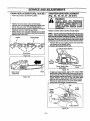
ROPE REPLACEMENT
(Fig. 54,55,56,57,58
Replace the chainwhen cutters or links break.
Use only the Low-Kickback replacement chain specified for your saw in the "Product Specifications."
See your Sears Service Center to repiace and sharpen
individual cb_tersfor matching your chain,
Always have a wornsprocket replaced by your Sears
Service Centerwhen installing a newohain to avoid excessive wear to the chain.
De?
I=,,H,
,H
" . 52 & 53 ) ........STARTER
(F,g
Move stop switch to the "STOP" position.
Cutters
/
==,m
AND ADJUSTMENTS
& 59 )
Replace a broken starter ropethat is badlyfrayed.
NOTE: A recoil spdng lies beneath the pulleyand is under
tension. If the re_. il spring is d'mt_,
€onsiderable
time and effort wdl be required to reinstall, Forthis reason you may want to let yourSears Service Center handle
thismpair._;If.youtryto repairthe starter rope and the recoil
.... spdng pops out,take:theunittoyourSears Service Center.
- Remove the four:fan housing screws and loosen the
two screws on the cylindercover.
Remove fan housing from the uniL
_ Cylinder Cover Screws
Drive Links
Figure 52
]
Housing
_ _=
Fan
Screw
"
-
Starter Rope Pulley
(other side)
Figure 54
Clutch Drum
& Sprocket
Screw ing
•
To take out rope tension, pull out 10" of rope. While
holdingdown pulley ratchet with thumb, pull several inches of rope hack intofan housingand catch in tab. Either hold pulley ratchet with thumb or hold starter .rope
handle. Release rope from the tab ano slowly aJiow
• _ pulley to turn counterclockwiseuntiltension is gone.
• •.Remove the pulley screw in the center of the pulley.
• Gentlytwist and lift pulley counterclockwise.
Figure 53
Tab
Pulley
Screw
Starter
Rope
Handle
__'-Pulley
Figure 55
-23-
Ratchet
Inll
II
I
.,,"l,,lll,',llll
I I
II I I
_
I
Ill
I I I
Ill
lU
II
IlllIlll
SERVICE AND ADJUSTMENTS
J,
i= =
III
f
I
U
Ill
=
UlllUllll
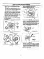
Remove the rope retainer screw and remove any remaining rope.
Move away from the fuel tank and melt the end of the
rope to be insta!led.Allow the melted end to droponce.
Then, while the rope is still hot, pull the melted and
through a rag to obtain a smooth, pointedend.
• Feed rope throughstarter rope hole in starter housing.
• Guide the rope inside the pulley, then up through the
pulley hole. it may be necessary to push the rope
through with a small Phillips screwdriver inserted into
the small hole on the underside of the pulley.
• Wrap rope counterclockwisearound the pulley ratchet
and tuck loose end back under rope, leaving a 1" tail
between the retainer rib and screw post.
• Pull rope tightly as shown in the figure below.
• Install the roperetainer screw and tighten until snug.
Do not over-tighten.
° Rewindat!,_he rope onto the pulley in a counterclockwise direction.
o
•
Pulley
Screw
i1
In
= nil,
o
JJjjJJjJJj Pu,,ey
Figure 58
•
•
Starter :--:
Housing _.
=,,,m,n
Twist and push pulley into _-_rter housing.
Replace and tighten the pulley screw.
•
Pull out 10" of rope and catch rope in tab in the pulley.
Carefully turn the pulley two completeturns clockwise,
winding up the springby releasing rope from the taD.
While holding the pulley ratchet, pug the excess rope
through the starter rope hole, While .hpld!ngtension on
the rope, let rope slowlYrewind intome housing.
Rope
Hole
Spring
p Spnng
Figure 56
"]
Rope Retainer
,,.,,,,
11111
" _
Tension
Figure 59
Rib
I 'PULLEY I
Re nstai fan housing by aligningthe fan housing tqthe
baffle plate and chassis. Then while ho cling the fan
housing against the chassis, pull the rope handle out
until you feelthe fan housing drop into place againstthe
chassis. Slowly, let the rope rewind intostarter housing.
Reinstall the 4 fan housing screws and tighten the 2 cylinder cover screws. Fig. 54.
Clockwise
Figure 57
-24-
...........................
SERVICE AND
..................................................
ADJUSTMENTS
i i
CARBURETOR
i
.,...H
i
.,,.,....
i
i
.m..i i i
.it
ADJUSTMENTS
Carburetor adjustment is critical and if done improperly can permanently damage the engine as well as the
carburetor. Please read all instructions and consult the Troubleshooting section of this manual before beginning
this process.
If engine does not start, it may be flooded. If in doubt, read
the section on flooded engine in the startingsection of this
manual prior to beginning any adjustments.
ff you are unsure about adjusting the carburetor or experience any problem while attempting this process, please
call the 1-800 number listed on the front cover of this
manual for further assistance.
CARBURETOR
(Figure
PRESETS
60 )
If your engine will not startdue to suspectedimpropercarburetoradjustrnent,the followingpresets may be required.
If used, it is recommended that all steps withinthe adjustment procedure be completed in order to assure a propedy
set carburetor. If presets are not needed, proceedto section =idle Speed Adjustment."
The carburetor has been adjusted at the factory for sea
Very small adjustments can affect engine performance,!t
level conditions. Adjustments may become necessary if
_is importantto turn the screw a very small.amountper aathe saw isused at significantlyhigt'ier altitudes or if you no-.,-justment
and test,performa(Lce'beforemaking turt.heraatJceany of the following conditions:
.justments.Each adjustment should be no more man me
widthof the slot in the adjusting screw.
- Chain moves when the engine runsat idle speed. See
=Idle Speed Adjustment."
• Turn both of the mixture screws countemlockwiseuntil
• Saw will not idle. See =Idle Speed Adjustment" and
they stop. Do not attempt to adjust the screw beyond
=Low Speed Mixture Adjustment. =
the stops as damage can occur.
• Engine dies or hesitates when it should accelerate.
• Turn idle speed screw clockwise 1/2 tum.
See =Acceleration Adjustment."
* Start the engine and operate for three (3) minutesto
• Loss of cutting powerwhich is not corrected by air filter
•
warm up. Go to =Adjusting Proceoure:
cleaning. See ,High Speed Mixture Adjustment."
NOTE: Do not attempt to adjust the screw beyond the
stops as damage can occur.
WARNING
THE CHAIN WILL BE MOVING DURING
MOST OF THIS PROCEDURE, WEAR
YOUR PROTECTIVE EQUIPMENT AND
OBSERVE ALL SAFETY PRECAUTIONS.
IN
"LOW
SPEED
MIXTURE
ADJUSTMENT," RECHECK IDLE SPEED
AFTER EACH ADJUSTME_.
THE CHAIN
MUST NOT MOVE AT IDLE SPEED ....
Figure 60
i
SERVICE AND ADJUSTMEN'FS
..........
ADJUSTING
PROC,:'DuR,:
.............................................
IDLE SPEED ADJUSTMENT '
• Allow the warm engine to idle,
• AdjusttheldteSpeedScrewuntiltheenginecontinues
to run without stallingand withoutthe chain moving.
-Turn screw clockwise to increase engine speed if
engine stalls or dies
-Turn screwcounterclockwise to slowengine down
and/or to keep the chain from turning
• No further adjustmentsare necessary if chaindoes not
move at idle speed and if performance is satisfactory
LOW SPEED MIXTURE ADJUSTMENT
• Allow engine to idle.
• Turn the Low Speed Mixture Screw slowlyclockwise
until the:RPM starts to drop. Note the position.
• Turn the:iLbWSpeed Mixture Screw slowly counterclockwise_ntil the RPM speeds up and starts to drop
again. NSte the position,
• Set the Low Speed MixtUre Screw at the midpoint be*
tween the two positions.
HiGH SPEED MIXTURE ADJUSTMENT
IMPORTANT: DO NOT OPERATE ENGINE AT FULL
THRO'I-FLE FOR PROLONGED PERIODS WHILE MAKING HIGH SPEED ADJUSTMENTS AS DAMAGE TO
THE ENGINE CAN OCCUR.
• Make a test cut.
•. Based on performance of the saw while cutting,adjust
the high speed mixture screw in 1/16 turn increments
as follows:
-Clockwise ff saw smokes or loses power in the cut
Do not adjust for best power by sound or speed,
but judge by how weft the saw performs in the
cut
-Oounterclockwise ff the sa whas speed whileout of
the cut, but dies in the cut or lacks power while
cutting
• Repeat the test cut
• Continue with 1/16 turn adjustments until the saw performanc_s acceptable while cutting.
• Aftercotnpletingadjustments,
checkforacceleration
ACCELERATION CHECK
• If the engine dies or hesitates instead of accelerating,
turn the Low Speed Mixture Screw 1/16 of a turn at a
timecounterclockwise untilyou have smoothacceleration.
• Check the idte speed for stability and no chain movement. Adjust as necessary.
• Recheck for smoeth acceleration and stable idle. Repeat process as necessary for acceptable performance
-26-
_
.....
THATIS
LEAN(CLOCKWISE
cAuTION: Too
A CARBURETORSETTING
ADJUSTMENT ON HIGH SPEED SCREW
FOR MAXIMUM SPEED) WILL CAUSE
ENGINE DAMAGE TO ANY 2-CYCLE
ENGINE FROM OVERHEATING AND LACK
OF LUBRICATION. NEVER SET THE HIGH:
SPEED SCREW SO FAR CLOCKWISE
THAT YOU HAVE HIGH ENGINE SPEED
LACKING POWER TO CUT. AN EFFECTIVE
APPROACH FOLLOWS.
-TURN HIGH SPEED SCREW COUNTERCLOCKWISE
UNTIL ENGINE
LOSES POWER WHILE CUTTING,
-TURN HIGH SPEED SCREW CLOCKWISE USING 1/16! TURN INCREMENTS ONLY UNTIL THE ENGINE
HAS POWER WHILE CLrI"TING;
IF THE ENGINE DOES NOT OPERATE
ACCORDING .TO THESE INSTRUCTIONS
AFTER
REPEATING THE ADJUSTING
STEPS, DO NOT USE THE UNIT. FOR
FURTHER ASSISTANCE, PLEASE CALL;
OUR CUSTOMER ASSISTANCE HOTLINE
AT 1-800-235"5878.
i
STORAGE
.......................
WARNING
ALLOW THE ENGINE TO COOL, AND
SECURE THE UNIT BEFORE STORING
OR TRANSPORTING IT IN A VEHICLE.
STORE UNIT AND FUEL IN AN AREA
WHERE FUEL VAPORS CANNOT REACH
SPARKS OR OPEN FLAMES FROM
WATER HEATERS, ELECTRIC MOTORS
OR SWITCHES, FURNACES, ETC.
,,,
,,
,
=,=
ENGINE
Never useengine orcerburetor cleanerproductsin thefuel
tank or permanent damage may occurto fuel systemcomponents.
Follow these instructions:
1. Drain the fuel from the unitinto an approved
fuel container.
2. Drain the fuel lines and carburetor by starting
the engine and lettJngit run until it stops.
3. Allow the engine to cool before storage.
immediately prepare your unfffor storage atthe end of the
season or if it will not be used for 30 days or mere,
IMPORTANT:
It is importantto prevent gum deposits
from formingin essentialfuel system partssuch as the carburetor, fuel filter, fuel line, or tank during storage. Also,
experience indicates that alcohol blended fuels called
gasohcl (or using ethanol or methanol) can attract tools.... ture" whichteade to:oil/gas-separation and formation of
acids during storage which wil! damage your engine. To
:__ avoid engineproblems, thefuel system shouldbe emptied
before storage of 30 days Or|0nger.
STORE UNIT WITH ALL GUARDS IN
PLACE. POSITION SO THAT ANY SHARP
OBJECT SUCH AS THE CHAIN CANNOT
•ACCIDENTLY
CAUSE
INJURY TO
PASSERS BY.
STORE THE UNIT OUT OF THE REACH
OF CHILDREN.
Fuel stabilizer is an acceptable alternative in rrdntmizing
the formation of fuel gum deposits dudng storage. Add
stabilizer to the gasoline in the fuel tank or fuel storage
container. Always followthe mix instructionstouna on stabilizer container. Run engine at least 5 minutes after adding stabilizer to allow stabilizer to reach the carburetor.
GAS CHAIN SAW STORAGE
INSTRUCTIONS
Craftsman 40:1 2-cycle engine oilis speciallyblended with
fuel stabilizers. If you do not use this SEARS oil,you can
add a fuel stabilizer (such as Craftsman #33500) to your
fuel tank.
• Remove spark plug and pour 1 teaspoon of 40:1 oil mix
through the spark plugopening. Slowly puUthe.starter
rope 8 to 10 times to distribute oi! to inner engine surfaces.
• Replace spark plug with a new one of the rectummended type and heat range. Referto =ProductSpecifications".
• Clean air filter. Refer to =Customer Responsibilities'.
• Reinstall all covers and hardware removed for access;
: tightenall screws and fasteners.
• Checkentire unitforlcosescrews, nuts, andbolts. Replace any damaged, broken, or wornparts.
• Use fresh fuel having the proper gasoline to oil ratio at
the beginning of the next season.
If yourchain saw is to be stored for a period of time, clean it
thoroughly prior to storage. Remove any dirt, sawdust,
leaves, oil, grease, etc. Store in a clean dry area.
•
Clean the entire unit.
•
Clean air filter. Refer to "Customer ResponstbiFdies".
inspect the barclamp area and clean any dirt, sawdust,
grass, or debris that has collected. Inspect the guide
bar and chain; replace a guide bar that is bent, warped,
cracked, broken, or damaged in any other way. Replace a damaged or worn chain.
Ughtly oil external metal surfaces to prevent rust from
forming.
•
Apply a coating of oil to the entire surface of the guide
bar and chain; wrap it in heavy paper, cloth, or plastic.
OTHER
• Do not store gasolinefrom one season to another.
• Replace your gasoline can if your can startsto rusL
Rust and/or dirt in your fuel system will cause problems.
• Store your unitin a well ventilated area and covered, if
possible, to prevent dust and dirt accumulation. Do not
cover with plastic. Plastic cannot breathe and will induce condensation and eventual rust or corrosion.
•
Be sure _l ha_dJesoandggaZds are,in place.and are.s_:
curety fastened. Replace any damaged parts,
IMPORTANT: Never cover uoitwhile engine and exhaust
areas are stillwarm.
j&
CAUTION: Wear protective gloves when
handling chain. The chain is sharp and
can cut you even when it is not moving.
I
-- 27 -
,,
i
n,ii
iiii
iiii
ii
TROUBLE SHOOTING
iii
iiiii
i
•
TROUBLE
,c
i
i
SHOOTING
sY i=TO .........
Engine will not start
or will run onlyfor
a few seconds after starting.
,,
,,111111 i
iiiiiiiiiii =l
IIIH
I
I
REMEDY
1.
2.
3.
4.
5,
Idte speed set too fast ortoo slow.
Low speed mixture requiresadjustment.
Crankshaft seals worn.
Compression low.
None of the above.
Engine will not
accelerate,lacks
power, or dies
under a load.
1.
2.
3.
4,
5.
6.
Air filter dirty.
Spark plug fouled.
Carburetor requires adjustment.
Exhaust ports or muffler outletsplugged.
Compressionlow.
None of the above.
, See "Starting Instructions."
inspectignition
fuel line.
1 Clean
Install fuel
new filter;
plug/check
system.
..........
i,
4.Air..er
2. Fuel mixture incorrect.
3.• High
mixture
Chokespeed
partially
on. requires adjustment.
5. Crankcase leak.
,., Hi
.,,,,,,
i
....11 Fill tank with correctfuel mixture
Engine will not idle
properly.
,
iii
cAusE
1. Fuel
1.
2.
3.
4.
5,
6.
7,
i i
CHART
Engine flooded.
Spark plug not fidngFuel not reaching carburetor.
Carburetor requires adjustment.
Stop Switch off.
None of the above.
Engine runs hot.
ml
POINTS
,,11111111 i
2•
3.
4.
5.
6.
7.
Engine
smokes
excessively.
ii
Fuel mixture incorrect.
High speed mixture set too low (Lean).
Spark plug incorrect.
Exhaust ports or muffler outlets plugged.
Carbon build-up on muffler outlet screen.
Fan housing]cylinder fins dirty.
None of the above.
.... i
..
i
,
i
switch to the
,START" position.
6_ Move
See "Carburetor
Adjustments."
_ Contact your Sears Service Ce,,nter/Dept.
1. See "Carburetor Ad ustrnents."
2. See "Carburetor Ad ustments."
3. Contact your Sears Service CentedDepL
4. Contact your Sears Service Center/Dept.
5, Contact your Sears Service Center/Dept:......
1.
2.
3.
4.
Clean or replace air filter.
Clean or replace spark plug arid re--gap,
See =carburetor A_ustments.
_
Contact your Sears Service Center/Dept.
5_
,
1.
2.
3.
4.
5,
Contact your Sears Service Center/Dept,
Contact your Sears Service,Center/Dept`
Clean or replace air filter.
Refuel with correct fuel mixture.
See =CarburetorAdjustments,"
Push Choke knob in.
Contact YourSears Service Center/Dept.
1.
2.
3.
4.
5.
6.
7.
See "Fueling Your Unit."
.
See "Carburetor Adjustments.
Replace with correct plug. _
_
.
Contact yourSears Service center/uep_.
Clean spark arrestor screen.
Clean area.
Contact your Sears Service Center/Dept.
H..ll
Oil inadequate for
bar and chain
lubrication.
1. Oil tank empty.
2. Oil pump or oil filter c_ogged.
3. Guide bar oil hole blocked•
1. RII oil tank.
2. Contact your Sears Service Center/Dept.
3, Remove bar and clean.
Chain moves at Idle
Speed.
1. Idte speed requires adjustrnenL
2. Clutch requires repa=r.
1. See =carburetor Adjustments,"
_
2. Contact your Sears Sewice Center/Dept.
,,,,H
,...,,.,,
.........
i
, i
i
,,,i,
,,. H i
Chain does not move t, Chain tension too tight•
when engine is
2. Carburetor requires adjustment.
accelerated.
3. Guide bar rails pinched.
4. Glut.ch slipping.
..................
i
Chain clatters
1. Chain tension incorrect,
or cuts roughly.
2. Cutters damaged.
3. Chain worn.
4. Cutters dull, impropedy sharpened, or
depth gauges too high.
5. Sprocket worn.
6.
Chain installed backwards.
,,,,,,,,,, ,
1.
: 2.
3.
4.
1,
2.
3.
4.
See "Chain Tension."
See =Carburetor Adjustments."
Repair or replace.
Contact your,Sears Service Center/DepL
See =Chain Tension•"
Contact your Sears Service CentedDept`
Resharpen or replacechain.
See the chain sharpening instructions.
5. Contact your Sears Service Center/Dept`
6. Install chain !n right direction.
...........
Chain stops within
the cut.
1. Chain cutter tops not filed flat•
2. Guide bar burred or bent; rails uneven.
3. Clutch slipping,
t. See the chain sharpening instructions.
2. Repair or replace guide bar.
3. Contact your Sears Service Center/Dept.
Chain cuts at an
angle.
1, Cutters damaged on one side,
1. Resharpen until all cutters have equal
angles and lengths.
2. Resharpen until all cutters have equal
angles and leng_.s....
3. Replace guide bar.
....
2. Chain dull on one side.
3. Guide bar bent or worn.
ff situations occur which are not covered in this manual, use care and good judgement.
ff you need assistance, contact your SEARS Service Center/Department
or the
CUSTOMER ASSISTANCE
HOTLINE at 1-800-235-5878.
-28,
29
......
...............
,,
,
,
,,,i ,.,,
i,
H
i
,,liH
H
j
JH
i
]l
REPAIR PARTS
ii
i
,i
,,,,,
,,,
,
,,,
,
J
i
N
i,,i
i
mini
]l ,
•
3O
,l,,,,l,ll,,,,
........
J
J,ll
3t
.............
i
i
iiiii
NOTES
,
iii iii
iii
i
i
..................
iiii
32
i
iiiiiiiiii
i
IIII
i
iiiiiii
33
NOTES
34
iiiiiiiiiiiii1[1111
i
/ I
II
I
I
IIIIIIIIIIIHII
IIIIII
I
TABLE OF CONTENTS
SateIy Rules .......................................................
"
ProductSpecifications ..........................
Customer Responsibilities ......................
'2
5
18
Warranty .............
_........................
Assembly
......................................
Operation .....................................
/
IIIIIII1_1/11/
I
,Service ana _oj'ustments ...............
Storage ......................................
Trouble Shooting .............................
"
5
7
9
' "'
27
28
Repair Parts ...............................
.................................
Accessories
Repair Parts Orderinq_ervice ..................
IIIIIIIIIIIIIIII
I
IIIIII
IIIII
/
I
23
_..
36
II]1111
gll /
II
iiiiiiiiiiiiiiiii
IIII
"
II
INDEX
i
i
iiiii i iiiii i
A
Accessories..................................
35
Adjusting Screw ................................
8
,ajr Filter ......................................
21
Assembly .....................................
7
B
Bar and Chain Oif .............................
16
Bucking ......................................
14
C
Carburetor Adjustments ........................
25
Chain Oiler ...................................
10
Chain Sharpening ..............................
19
Customer Responsibilities ......................
18
Spark Plug ................................
21
CuttingTechniques ............................
10
E
Engine
FueIIOil...................................
16
Spark Plug ................................
21
Starting ...................................
17
Storage ...................................
27
F
Fuel Filter ....................................
22
Fueling ......................................
16
G
Guide Bar Lubrication ..........................
19
H
Hardware Contents .............................
6
IIIIIIIIIIIIII
I II I
III
I!
K
Know Your Gas Chain Saw ......................
9
L
Limbing ......................................
15
M
Maintenance Schedule .........................
18
Model Number .................................
4
Muffler .......................................
22
O
Operation .....................................
g
OrderingRepairParts...........................
36
P
Pruning .........................................
15
R
Repair Parts ..................................
29
S
Service and Adjustments ....................
... 23
Spark Arrestor Screen .........................
22
Specifications ..................................
4
Starter Rope ..................................
23
Starting ......................................
17
Storage ......................................
27
T
Tree Felling ..................................
12
Trouble Shooting .....................
, ........
28
W
Warranty ..........................
............
4
..............................
II I[
i im......i,
i
....
ACCESSORIES
These accessories and attachments were available when the unit was originally purchased. They are also available at
most Sears retait outlets and service centers. MostSears stores can order these items foryou when you provide the model
number of your unit.
PERFORMANCE
Spark Plug
Air Filter
2-cycle
Engine
Oil
.......
" ....
BarOil .......
3.20:"
80777
16o:'-
lqL
lgat.
MAINTA1NENCE
Carrying
ii
Gloves
Guide Bar
Safety
Goggles
-35
-
Chain
Hearing
Protection
¸Chain
Sharpener
,,,,, ,,,,
.,
i,
i
i i i
CRRFTSHRN°
2,5 cu. in J36 cc 2 CYCLE
18 in. Guide Bar
Operator's
Manual
GASOLINE CHAIN SAW
Model No.
358.356242
Each Gasoline Chain Saw has itsown model number. The model
number for your unit will be found on a decal attached to the unit.
All parts listedherein may be orderedthrough Sears, Roebuckand
Co, Service Centers and most Retail Stores.
IF YOU NEED REPAIR
SERVICE OR PARTS:
WHEN ORDERING REPAIR PARTS, ALWAYS GIVE THE FOLLOWING INFORMATION
. PRODUCT-
REPAIR SERVICE
1-800-4-REPAIR
(1-800-473-7247)
=GASOLINE CHAIN SAW"
• MODEL NUMBER-358.356242
. PART NUMBER
• PART DESCRIPTION
ORDERING PARTS
1-800-FON-PART
(1-800-366-7278)
YourSears merchandise has added value when you considerthat
Sears has service units nationwidestaffed with Sears trained technicians..: professional technicians specifically trained on Sears
products, having the parts, tools and the equipment to insure that
we meet our pledge to you, we service what we sel!.
• /
Sears,
,,,
Roebuck
,
,,,i,
and Co., Hoffman
Estates,
IL 60179
USA