1
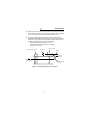
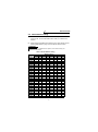
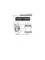
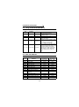
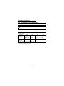
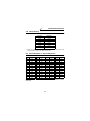
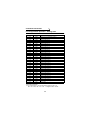
TRANSISTORIZED INVERTER
-INSTRUCTION MANUAL-
Modbus Plus COMMUNICATION OPTION
FR-A5NM
Thank you for choosing the Mitsubishi transistorized inverter option unit.
This instruction manual gives handling information and precautions for use of
this equipment. Incorrect handling might cause an unexpected fault. Before using
the equipment, please read this manual carefully to use the equipment to its
optimum.
This section is specifically about safety matters
Do not attempt to install, operate, maintain or inspect this product until you
have read through this instruction manual and appended documents carefully
and can use the equipment correctly. Do not use this product until you have a
full knowledge of the equipment, safety information and instructions.
In this instruction manual, the safety instruction levels are classified into
"WARNING" and "CAUTION".
WARNING
Assumes that incorrect handling may cause
hazardous conditions, resulting in death or
severe injury.
CAUTION
Assumes that incorrect handling may cause
hazardous conditions, resulting in medium or
slight injury, or may cause physical damage only.
Note that the CAUTION level may lead to a serious consequence according to
conditions. Please follow the instructions of both levels because they are
important to personnel safety.
SAFETY INSTRUCTIONS
1. Electric Shock Prevention
WARNING
• While power is on or when the inverter is running, do not open the front
cover. You may get an electric shock.
• Do not run the inverter with the front cover removed. Otherwise, you may
access the exposed high-voltage terminals and charging part and get an
electric shock.
• If power is off, do not remove the front cover except for wiring or periodic
inspection. You may access the charged inverter circuits and get an electric
shock.
• Before starting wiring or inspection, switch power off, wait for more than 10
minutes, and check for no residual voltage with a tester or the like.
WARNING
• Any person who is involved in the wiring or inspection of this equipment
should be fully competent to do the work.
• Always install the option unit before wiring. Otherwise, you may get an
electric shock or be injured.
• Handle this option unit with dry hands to prevent an electric shock.
• Do not subject the cables to scratches, excessive stress, heavy loads or
pinching. Otherwise, you may get an electric shock.
• While power is on, do not move the station number and baud rate setting
switches. Doing so can cause an electric shock.
A-1
2. Injury Prevention
CAUTION
• Apply only the voltage specified in the instruction manual to each terminal to
prevent burst, damage, etc.
• Ensure that the cables are connected to the correct terminals. Otherwise,
burst, damage, etc. may occur.
• Always make sure that polarity is correct to prevent burst, damage, etc.
• While power is on or for some time after power-off, do not touch the inverter
as it is hot and you may get burnt.
3. Additional instructions
Also note the following points to prevent an accidental failure, injury, electric
shock, etc.:
(1) Transportation and mounting
CAUTION
•
•
•
•
Do not install or operate the option unit if it is damaged or has parts missing.
Do not stand or rest heavy objects on the product.
Check that the mounting orientation is correct.
Prevent screws, metal fragments or other conductive bodies or oil or other
flammable substance from entering the inverter.
(2) Test operation and adjustment
CAUTION
• Before starting operation, confirm and adjust the parameters. A failure to do
so may cause some machines to make unexpected motions.
(3) Usage
WARNING
• Do not modify the equipment.
CAUTION
• When parameter clear or all parameter clear is performed, each parameter
returns to the factory setting. Re-set the required parameters before starting
operation.
• For prevention of damage due to static electricity, touch nearby metal before
touching this product to eliminate static electricity from your body.
(4) Maintenance, inspection and parts replacement
CAUTION
• Do not test the equipment with a megger (measure insulation resistance).
(5) Disposal
CAUTION
• Treat as industrial waste.
(6) General instruction
All illustrations given in this manual may have been drawn with covers or safety
guards removed to provide in-depth description. Before starting operation of
the product, always return the covers and guards into original positions as
specified and operate the equipment in accordance with the manual.
A-2
CONTENTS
1. INTRODUCTION
1.1
1.2
General ............................................................................................. 1
Structure ........................................................................................... 2
2. INSTALLATION
2.1
2.2
2.3
4
Pre-Installation Checks..................................................................... 4
Node address setting........................................................................ 7
Communication cable ..................................................................... 10
3. OPERATION
3.1
3.2
3.3
1
12
Operating Modes ............................................................................ 12
Selecting the Operating Mode ........................................................ 12
Functions Available in the Operating Modes .................................. 13
4. ACCESSING DRIVE DATA
14
5. PARAMETER DEFINITIONS
15
5.1
Input to Inverter From Modbus Plus Network (Control Input
Command) ...................................................................................... 17
5.2 Output From Inverter to Modbus Plus Network (Inverter Status).... 18
5.3 System Environment Variable (SEV) Interface............................... 19
5.4 Using the Modsoft MSTR Block...................................................... 20
5.5 Real-Time Monitor .......................................................................... 20
5.6 Input/Output Terminal Assignment ................................................. 22
5.7 Operation When an Alarm Occurs.................................................. 22
5.8 Alarm History .................................................................................. 23
5.9 Alarm Numbers vs. Alarm Definitions ............................................. 23
5.10 A500(L) PARAMETERS ................................................................. 24
5.10.1 Normal Parameter Area.......................................................... 24
5.11 900f Parameter Area ...................................................................... 25
5.12 900% Parameter Area .................................................................... 25
5.13 Programmed Operation : Setting Time ........................................... 26
5.14 Programmed Operation : Setting Rotation Direction ...................... 27
5.15 Programmed Operation : Frequency Setting .................................. 28
6. SPECIFICATIONS
29
Appendix A. Other Option-Specific parameters
30
1. INTRODUCTION
1.1 General
Thank you for choosing this option unit for the Mitsubishi FR-A500(L)/
F500(L) series transistorized inverters.
Please read this manual carefully before using this option unit. This
instruction manual gives handling information and precautions for use of
this product as well as the information required for the transmission of data
to and from the inverter via a Modbus Plus network.
It is assumed that the reader of this manual possesses an understanding
of the configuration, implementation, and operation of Modbus Plus
networks. For details on the Modbus Plus network protocol and/or Modbus
Plus network configuration and installation, please refer to the applicable
specifications as published by Schneider Automation.
Please forward this manual to the end user.
Modbus Plus Communications Option Unit
(FR-A5NM)
This option unit lets you connect a FR-A500(L) series inverter to a
network adhering to the Modbus Plus communications protocol.
Some important features of this option unit include:
• Data rate of 1 M bps
• Support for up to 32 nodes without a repeater (64 nodes with a repeater)
on a single network
• Network access to all inverter parameters
• Passed Modicon Conformance Test in March, 1999
Company and product names in this manual are trademarks or registered
trademarks of their respective owners.
1
INTRODUCTION
1.2 Structure
Mounting Hole
Modbus Plus Connector
Earth (Ground) Terminal
Plastic nut
Mounting Hole
Status LED
Plastic nut
Node address
Switch
Figure 1: Top view
Mounting Hole
Option Fixing Hole
Option Connector
Figure 2: Bottom view
2
INTRODUCTION
Diagnostic LED Status Indicator
The green LED located next to the address DIP switch on the Modbus
Plus option top board provides indication of communication status. The
LED on the bottom board will be solid green if the option CPU acts
correctly.
The following describes the LED on the top board definitions.
Green
Flash every 160ms
Flash every 1s
2 flashes, off 2s
3 flashes, off 1.7s
4 flashes, off 1.4s
State of system
Node is working normally. It is successfully
receiving and passing the network token.
Node is in the MONITOR_OFFLINE state. It
monitors the network link every 5 seconds
but is not transmitting.
Node is in MAC_IDLE state. This node may
have a bad transmitter.
Node is not receiving tokens. This indicates
that this node is the only active node on the
network or the receiver is bad.
Duplicate node address seen.
Table 1
3
2. INSTALLATION
Remove the drive cover following the inverter instruction manual and
install the option unit using the following procedure:
2.1 Pre-Installation Checks
(1) Check the inverter type.
You may use the option unit only with a FR-A500(L)/F500(L) series
inverter. You must not use it with any other series (e.g. A200E, A200,
A100, Z and F series). These other series inverters have a different
option connector to prevent installation; if you force the connector, you
may damage the inverter as well as the option unit.
(2) Make sure the inverter line power is off.
You may damage the option unit if you install it with the line power
connected.
Mounting Procedure
CAUTION
HAZARDOUS VOLTAGE PRESENT
Always isolate power from the inverter and wait 10 minutes
until the bus charge light is off to ensure the charge lamp has
gone out before inserting or removing this option unit or
touching the terminals.
(3) Insert this option unit into the inverter's OPTION PORT# 3 only.
(4) Carefully insert the connector of the option unit into the connector of
the inverter. Use the two mounting holes and the guide hole to align
the bottom board with the matching machine screw inserts and the
plastic guide pin on the inverter. Make sure that the inverter option is
firmly seated in the inverter and the connector is fully plugged in.
Also be sure to fit the unit into the option fixing hook (It is available in
Aug., 2000).
REMARKS
When you insert the option unit to the inverter, please push down the plastic
nuts on the top-board. (Please refer to Figure 1)
4
INSTALLATION
(5) Secure the option unit to the inverter with two mounting screws. If the
screw holes in the option unit do not line up with the inverter mounting
holes, check that the connectors have been fitted correctly.
(6) To ensure proper Network Grounding, connect a harness (NOT
Supplied) from FR-A5NM Ground terminal to inverter Ground terminal.
For ease of routing, the harness should be passed between the Top
and Bottom board. (Refer to the following diagram.)
Recommended crimping terminal : 1.25-3
Recommended Ground harness size : 16AWG
Torque to 0.4 - 0.7Nm
DB9 connector
Node address DIP switch
M3 screw
M3 nut
Crimping
terminal
To GND terminal
of the inverter
Earth (Ground)
harness
Figure 3 : Earth (Ground) harness connection
5
INSTALLATION
(7) Set the node address before replacing the cover onto the inverter.
(Refer to page 7 for node address setting.)
(8) Next remove the option data port insert from the inverter cover. Then
replace the inverter cover, while making sure that the Modbus Plus
connector is aligned with the option data port window. Connect the
Modbus Plus cable to the inverter by plugging DB9-style male
connector into DB9-style female connector of the option unit, which
should be visible in the option port window.
(9) Please consult and adhere to standard Modbus Plus documentation
and specifications on the wiring and installation of Modbus Plus
network hardware, as provided by Schneider Automation.
Slot 1
Slot 2
Cover
Modbus Plus
connector
Slot 3
FR-A5NM
M3×8 screw
(accesory)
DATA PORT
Inverter
Option mounting
hole
To inverter GND terminal
Modbus Plus connector
FR-A5NM
Control circuit
terminal block
Main circuit
terminal block
Inverter GND terminal
Figure 4 : Installation
6
INSTALLATION
2.2 Node address setting
(1) Make sure that the inverter power is off and the option unit is mounted
in the inverter. Connect the Modbus Plus cable you created to the
network.
(2) When setting the Modbus Plus address on the option board, use the
following table. Refer to page 2 for the address switch location.
REMARKS
A switch setting of 1 indicates the On position, and a switch setting of 0
indicates the Off position.
Table 2 : Node address setting
Decimal
Address
3
4
5
6
7
8
9
10
11
12
13
14
15
16
17
18
19
20
21
22
23
24
25
26
27
1
1
0
1
0
1
0
1
0
1
0
1
0
1
0
1
0
1
0
1
0
1
0
1
0
1
2
0
0
1
1
0
0
1
1
0
0
1
1
0
0
1
1
0
0
1
1
0
0
1
1
0
3
1
1
0
0
0
0
1
1
1
1
0
0
0
0
1
1
1
1
0
0
0
0
1
1
1
Switch Positions
4
5
1
1
1
1
1
1
1
1
1
1
1
1
0
1
0
1
0
1
0
1
0
1
0
1
0
1
0
1
1
0
1
0
1
0
1
0
1
0
1
0
1
0
1
0
0
0
0
0
0
0
7
6
1
1
1
1
1
1
1
1
1
1
1
1
1
1
1
1
1
1
1
1
1
1
1
1
1
7
1
1
1
1
1
1
1
1
1
1
1
1
1
1
1
1
1
1
1
1
1
1
1
1
1
8
1
1
1
1
1
1
1
1
1
1
1
1
1
1
1
1
1
1
1
1
1
1
1
1
1
INSTALLATION
Decimal
Address
Switch Positions
4
5
0
0
0
0
0
0
0
0
0
0
1
1
28
29
30
31
32
33
1
0
1
0
1
0
1
2
0
1
1
0
0
1
3
1
0
0
0
0
1
34
35
36
37
38
39
0
1
0
1
0
1
1
0
0
1
1
0
1
1
1
0
0
0
1
1
1
1
1
1
40
41
42
43
44
45
46
47
48
49
50
51
52
53
54
55
56
57
58
59
60
61
62
63
0
1
0
1
0
1
0
1
0
1
0
1
0
1
0
1
0
1
0
1
0
1
0
1
0
1
1
0
0
1
1
0
0
1
1
0
0
1
1
0
0
1
1
0
0
1
1
0
0
1
1
1
1
0
0
0
0
1
1
1
1
0
0
0
0
1
1
1
1
0
0
0
1
0
0
0
0
0
0
0
0
1
1
1
1
1
1
1
1
0
0
0
0
0
0
0
8
6
1
1
1
1
1
0
7
1
1
1
1
1
1
8
1
1
1
1
1
1
1
1
1
1
1
1
0
0
0
0
0
0
1
1
1
1
1
1
1
1
1
1
1
1
1
1
1
1
1
1
1
1
1
0
0
0
0
0
0
0
0
0
0
0
0
0
0
0
0
0
0
0
0
0
0
0
0
0
0
0
0
0
0
0
0
0
0
0
0
0
0
0
1
1
1
1
1
1
1
1
1
1
1
1
1
1
1
1
1
1
1
1
1
1
1
1
1
1
1
1
1
1
1
1
1
1
1
1
1
1
1
1
1
1
1
1
1
1
1
1
INSTALLATION
Alternate method for setting the switch:
i.
ii.
iii.
iv.
To set the node address to be nn, first subtract 1 from it.
Convert the result (nn-1) into hexadecimal XXh.
Then span it into binary format, padding with 0's in the front 00fedcba.
Finally, take the complement 11nmlkji, if a bit is 0, set the switch to Off
position; if a bit is 1, set the switch to On position.
REMARKS
The first two leading position switches are not used.
For example, to set the node address to 30, do the following:
a. Convert the result 29=30-1 into 1Dh
b. Span into 8-bit format 00011101
c. Take the complement 11100010
d. Set 8 positions according to c
0
4
0
0
3
1
1
0
2
6
5
1
1
7
1
8
ON
Figure 5 : Node address switch
9
INSTALLATION
2.3 Communication cable
When making a cable for the Modbus Plus protocol, make sure that each
end of the cable is terminated with the A5MBKT185 terminator connectors.
For nodes between the termination points, use the in-line connectors
(A5MBKT085). The cable should be a Modbus Plus standard cable
(490NAA271xxF).
Connect a wire from the ground terminal on the FR-A5NM to the
inverter Chassis to ensure proper grounding of the option board.
Makers of DB9 connectors, Schneider Automation:
• End Connector Part#: AS-MBKT-185 (light gray)
• Inline Connector Part#: AS-MBKT-085 (dark gray)
Figure 6 : Modbus connector
10
INSTALLATION
Please connect Modbus connector and the communication cable following
the table.
Connector pin number
1 (Signal)
2 (Shield)
3 (Signal)
Communication cable
Signal (Blue or Black)
Shield
Signal (White)
(*) Another connector pins are not used
Shield
Shield
Signal
(Blue or Black)
Signal (White)
Signal (Blue or Black)
Signal (White)
Modbus connector
top view
9
8
7
6
1
2
3
1
5
4
3
2
1
Connector pin number
Modbus Plus
communication cable
Modbus connector side
view
Figure 7 : Communication cable connection
11
3. OPERATION
The operation of the inverter changes slightly when you install this option
unit, as described below.
3.1 Operating Modes
In the PU operating mode, a Parameter Unit (PU) controls the inverter. In
the External-operating mode, the inverter is controlled by external signals
connected to the inverter's terminal block. In the Network (computer link)
operating mode, the inverter is controlled by commands from a Modbus
Plus master.
3.2 Selecting the Operating Mode
The following conditions must also be met before you can change the
operating mode:
• The inverter is stopped.
• The forward and reverse commands are off.
The following table describes the actions required to change the operating
mode.
Mode Change
Ext Operation → PU Operation
PU Operation → Ext Operation
Ext Operation → Net Operation
Net Operation → Ext Operation
Action Required
Select the PU operation mode from the
operation panel or press PU key on the
parameter unit.
Select the EXT operation mode from the
operation panel or press EXT key on the
parameter unit.
Modbus Plus master writes a 0014h to
Register 40010.
Modbus Plus master writes a 0010h to
Register 40010.
For all other mode changes, please refer to the Inverter Instruction
Manual.
Pr. 340 allows you to select the Network operating mode on power-up and
after a drive reset. Once the Network operating mode is initiated, there
must be Modbus Plus activity at least once every 3 seconds. If the option
unit does not sense valid Modbus Plus activity for 3 seconds or more, the
inverter performs an option module alarm stop (E.OP3), and you must
reset the inverter to clear this fault.
12
OPERATION
3.3 Functions Available in the Operating Modes
The functions available to the drive depend on the operating mode.
The following table indicates the command types available according to
the operating mode.
Control Type
Modbus Plus
External
Terminals
Command Type
Operating
Command
Output
Frequency
Setting
Monitor
Parameter Write
Parameter Read
Inverter Reset
Operating
Command
Output
Frequency
Setting
Inverter Reset
Net
Ext
PU
Yes(*1)
No
No
Yes(*1)
No
No
Yes
Yes(*2)
Yes
Yes(*3)
Yes
No(*2)
Yes
No
Yes
No(*2)
Yes
No
Yes(*1)
Yes
No
Yes(*1)
Yes
No
Yes
Yes
Yes
*1 Depends on the value of Pr. 338 and Pr. 339.
*2 Depends on the value set in Pr. 77.
Refer to the Inverter Instruction Manual for further information.
*3 If a network communication error has occurred, a manual resewill be required.
13
4. ACCESSING DRIVE DATA
(1) This option unit acts as a Modbus Plus slave to a PLC or equivalent
controller acting as a Modbus Plus master.
This means that the option unit:
• Acknowledges messages received
• Transmits messages at the request of a network master.
(2) The option unit can also act as a Modbus Plus slave to a Modbus Plus
master that can read the drive's I/O values, as well as configure the
drive itself.
(3) The option unit cannot send messages on its own, and it has no bus
access rights. It also cannot simultaneously act as a slave to network
master and as a lead drive (master) to follower drives (slaves).
(4) This option unit does not support any other manufacturer-specific
messages or parameters.
(5) The Modbus Plus network is designed to allow individual devices to be
taken off-line without affecting the other devices on the network. For
example, if an invertr exists on a Modbus Plus network consisting of a
master and 1 or more other slave devices, deactivating or disabling the
master will not result in a Modbus Plus network error; therefore, the
inverter will not experience a fault and will continue to run based upon
the last valid commnad received.
14
5. PARAMETER DEFINITIONS
Depending upon which Modbus Plus master device is being used, data
registers may be referenced using a 5-digit(4nnnn) or 6-digit(40nnnn)
format. For convenience, this manual uses the 5-digit format. When using
the 6-digit format, the last 4 digits of the register remain the same and a
zero is inserted between the numeral 4 and the 4-digit register
number(nnnn).
The Modbus Plus option card generates error codes when inappropriate
operations occur. These codes are stored in register 40020(9C54h)
If a write occurs to the inverter while the inverter is in EXT mode, a 41h will
exist in register 40020. If a write occurs to the Real Time Monitor or the
Alarm History, 42h will exist in register 40020. 43h will exist in register
40020 if an out of range value is written to any parameter. See more error
code listings in the table below:
Error Codes for FR-A5NM
Error codes for FR-A5NM are stored in Extended Error Code Register
40020.
Code
01h
03h
Definition
Unsupported Task (*1, 2, 3)
Invalid Register
04h
DPR Read Failure
05h
Write Cmd Failure
41h
Mode Error
42h
Instruction Error
43h
Data Range Error
Explanation
You request an unsupported Task.
You use an undefined register.
You cannot read such data from Dual
Port RAM.
You cannot write data to this register.
e.g. You try to write to the register
41000(Pr. 0) while inverter is running.
e.g. You try to write to Real Time Monitor
because it is read only.
You try to write an out of range data to
this register.
*1 Writing invalid data to Op Mode Register 40010 is not allowed and answered
"01 unsupported task" in the Error Code Register 40020.
*2 Access to undefined Registers in A5NM is answered "01 unsupported task" in
the Error Register 40020.
*3 Reading invalid Monitor data, writing to Pr. 77, Pr. 79 are answered "01
unsupported task" in the Error Register 40020.
15
PARAMETER DEFINITIONS
Read out data:
FFFEh means No parameter.
FFFDh means parameter Not Available.
Any register that does not appear in any entry of the following tables is
considered Reserved.
Examples for reading from and writing to parameters:
Operation
Read Parameter 0
Start running forward
Stop the drive from running
Enable Net Mode
Enable EXT Mode
Communication Function
Read from Register 41000
Write a 2 to Register 40009
Write a 0 to Register 40009
Write a 14h to Register 40010
Write a 10h to Register 40010
16
PARAMETER DEFINITIONS
5.1 Input to Inverter From Modbus Plus Network
(Control Input Command)
To change the inverter Control Input Cmd, write the word value to Register
40009.
The following table describes the bit-map for the inverter Ctrl Input Cmd
word value.
Write a value to register 40009 to give an operation command to the
inverter. The bit-map values of the control instructions to the inverter are
listed in the following table.
Bit
Definition (Signal)
Terminal
0
Not used and always set to 0
—
1
1 = Forward rotation (STF signal)
STF
2
1 = Reverse rotation (STR signal)
STR
3
1 = Low speed operation (RL signal) *1
RL
4
1 = Middle speed operation (RM signal) *1
RM
5
1 = High speed operation (RH signal) *1
RH
6
1 = Jog operation selection (JOG signal) *1
JOG
7
1 = Second function selection (RT signal) *1
RT
8
1 = Current input selection (AU signal) *1
AU
9
1 = Instantaneous power failure restart selection (CS signal) *1
CS
10
1 = Output stop (MRS signal)
—
11 to 15 Not used and always set to 0
—
*1 These are factory-set signals. Input signals can be switched by Pr. 180 to Pr.
186 (input terminal function selection). Refer to the inverter manual for details
of input terminal function selection.
17
PARAMETER DEFINITIONS
5.2 Output From Inverter to Modbus Plus Network
(Inverter Status)
To check the inverter status, read the word out from Register 40009 or
40019.
The following table describes the bit-map for the inverter status word.
Definition
Bit
Inverter Status 1
(40009)
Inverter Status 2
(40019)
Terminal
—
1 = Inverter running (RUN signal) 1 = Forward running
1 = Forward running
1 = Reverse running
—
1 = Inverter running
RUN
2
1 = Reverse running
(RUN signal) *1
3
1 = Up to frequency (SU signal) 1 = Up to frequency (SU signal) *1
SU
1 = Instantaneous power failure or
IPF
4
1 = Overload alarm (OL signal)
under voltage (IPF signal) *1
1 = Instantaneous power failure
OL
5
1 = Overload alarm (OL signal) *1
or under voltage (IPF signal)
1 = Frequency detection
1 = Frequency detection
FU
6
(FU signal)
(FU signal) *1
7
1 = Alarm output (ABC signal) 1 = Alarm output (ABC signal) *1
ABC
8 to 14
Not used
Not used
—
1 = Alarm output
15
(ABC signal inversion)
*1 These are factory-set signals. Output signals can be switched by Pr. 190 to Pr.
195 (output terminal function selection). Refer to the inverter manual for details
of output terminal function selection.
0
1
18
PARAMETER DEFINITIONS
5.3 System Environment Variable (SEV) Interface
40009
Inverter Status 1/CtrlInpCmd (*4)
R/W
40010
40013
40014
OpMode / Inverter Config
f Sett Val
Runng f (RAM) (*6)
R/W
R/W
R/W
WriteVal
0000h
XXXXh
965Ah
99AAh
5A55h
5A96h
AA99h
555Ah
00XXh/
0XXXh
(*5)
ffggh
ffggh
40015
Runng f (E2PROM) (*6)
Inverter Status 2 (*7)
WO
ffggh
Inverter Reg
40001
40002
40003
40004
40005
40006
40007
40008
40019
Definition
UsrClrValSett
Inverter Reset (*2)
PrClr
PrAllClr
PrUsrClr
PrClr (*3)
PrAllClr (*3)
PrUsrClr (*3)
Access (*1)
WO
WO
WO
WO
WO
WO
WO
WO
RO
—
*1 Regarding access
WO ........ Only writing is enabled (reading is disabled)
RO......... Only reading is enabled (writing is disabled)
R/W ....... Both reading and writing are enabled
*2 Writing any value to the parameter 40002 resets the inverter.
*3 Communication parameter (Pr. 117 to Pr. 124, Pr. 331 to Pr. 342) are not
cleared.
*4 For read values of inverter status and write values of control input command,
refer to page 17, 18.
*5 For read values of operation mode and inverter setting, refer to the table below.
Operation Mode
External operation mode
PU operation mode
External jog mode
PU jog mode
Net mode
Combined mode
Programmed operation mode
Read Value
0000h
0001h
0002h
0003h
0004h
0005h
0006h
Write Value
0010h
0011h
—
—
0014h
—
—
Programmed operation mode is displayed only for the FR- A500(L) series.
*6 Writing to Register 40014 or 40015 can be read out from Register 40014.
*7 For read values of inverter status 2, refer to page 18.
19
PARAMETER DEFINITIONS
5.4 Using the Modsoft MSTR Block
The MSTR control register usage is as follows:
PLC
Register
Register
Value
Value Base
Description
Commands MSTR function:
1 = write; 2 = read
n+1
xxxx
hexadecimal MSTR function error code
Number of registers to be written/read
n+2
1
decimal
to /from the inverter
Specifies the inverter register to write/
read to/from. Value represents an
n+3
rrrr
decimal
offset starting w/register 40000
(i.e. 1 = 40001; 49 = 40049).
Routing registers contain Modbus Plus
nodes for communication routing. The
first register following the register
n+4, 5, 6, 7 node number
decimal
containing the inverter node number
must contain a 1 value. Remaining
routing registers must contain a 0
value.
n
1,2
decimal
5.5 Real-Time Monitor
Register
Definition
40201
40202
40203
40205
40206
40207
40208
40209
RTM01 Outp f
RTM02 Outp I
RTM03 Outp V
RTM05 f Sett Val
RTM06 Runng Spd
RTM07 Motor Torq
RTM08 Convrtr Outp V
RTM09 Regen Brake Duty
RTM10 Electr Overcur Protectn
Load Factr
RTM11 Outp I Peak
RTM12 Converter Peak Outp V
RTM13 Inverter Input Powr
RTM14 Inverter Output Powr
40210
40211
40212
40213
40214
20
Minimum Setting Minimum Setting
Increments
Increments
(A500, F500)
(A500L, F500L)
0.01Hz
0.01Hz
0.01A
0.1A
0.1V
0.1V
0.01Hz
0.01Hz
1r/min
1r/min
0.1%
0.1%
0.1V
0.1V
0.1%
0.1%
0.1%
0.1%
0.01A
0.1V
0.01kW
0.01kW
0.1A
0.1V
0.1kW
0.1kW
PARAMETER DEFINITIONS
Register
40215
40216
40217
40218
40219
40220
40222
40223
40224
40225
Minimum Setting Minimum Setting
Increments
Increments
(A500, F500)
(A500L, F500L)
—
—
RTM15 Inp Termnl Status (*1)
RTM16 Outp Termnl Status (*2)
—
—
RTM17 Load Meter
0.1%
0.1%
RTM18 Motor Excitatn I
0.01A
0.1A
RTM19 Positive Pulse
—
—
RTM20 Cumulative Energ t
1h
1h
RTM22 Orientatn Status
—
—
RTM23 Actl Op t
1h
1h
RTM24 Motor Load Factr
0.1%
0.1%
RTM25 Cumulative Powr
1kWh
1kWh
Definition
*1 Bit-Map for Register 40215
Input Terminal Monitor:
15..12
0
11
CS
10
RES
9
STOP
8
MRS
7
JOG
5
RM
4
RL
3
RT
2
AU
1
STR
0
STF
3
OL
2
IPF
1
SU
6
RH
*2 Bit-Map for Register 40216
Outp Terminal Monitor:
15..6
0
5
Relay
4
FU
0
RUN
The bit-wise data here reflect Pr. 190 to 195; if assignments for terminals are
changed, the bit-map may not be the same.
REMARKS
Modbus Plus is a single command machine. Only one command can be sent to
the FR-A5NM at a single time. Multiple commands to a single slave is NOT
supported. Please send one command for each terminal assignment.
21
PARAMETER DEFINITIONS
5.6 Input/Output Terminal Assignment
CAUTION
Input/output terminal assignment functions depend upon
programmed functions such as brake sequences
5.7 Operation When an Alarm Occurs
The following table shows the behavior of the inverter and network when
an alarm occurs:
Fault Type
Inverter (*2)
Modbus Plus
Comm. (*3)
Item
Inverter
Operation
Network Comm.
Inverter
Operation
Network Comm
Net
Ext
PU
Stop
Stop
Stop
Continue
Continue
Continue
Stop
Continue
Continue
Continue (*1)
Continue (*1)
Continue (*1)
*1 Depends on the type of communication fault.
*2 For example, E.OP3, E.OC3.
*3 For example, Slow blinking LED
22
PARAMETER DEFINITIONS
5.8 Alarm History
Register
40501
40502
40503
40504
40505
40506
40507
40508
Definition
Alarm 1 (*1)
Alarm 2
Alarm 3
Alarm 4
Alarm 5
Alarm 6
Alarm 7
Alarm 8
*1 Writing any value to parameter 40501 resets the alarm history buffer for all
alarms. All other entries in this table are read only.
5.9 Alarm Numbers vs. Alarm Definitions
#
10
11
12
20
21
22
30
31
40
41
50
51
60
70
Definition
OC1
OC2
OC3
OV1
OV2
OV3
THT
THM
FIN
FAN
IPF
UVT
OLT
BE
#
80
81
90
A0
A1
A2
A3
B0
B1
B2
C0
C1
C2
D0
Definition
GF
LF
OHT
OPT
OP1
OP2
OP3
PE
PUE
RET
CPU
CTE
P24
OS
#
D1
D2
D3
D4
D5
D6
D7
D8
D9
DA
DB
F0
F1
F2
Definition
Osd
ECT
Od
ECA
Mb1
Mb2
Mb3
Mb4
Mb5
Mb6
Mb7
E0
E1
E2
#
F3
F4
F5
F6
F7
F8
F9
FA
FB
FC
FD
FE
FF
Definition
E3
E4
E5
E6
E7
E8
E9
E10
E11
E12
E13
E14
E15
Please refer to the Inverter Instruction Manual for an explanation of Alarm
Definitions.
23
PARAMETER DEFINITIONS
5.10 A500(L) PARAMETERS
5.10.1
Normal Parameter Area
You can use the Register to make parameter settings from the network.
The last three digits of Register are the parameter number.
Standard parameter examples are introduced below. Refer to the
examples and make parameter settings.
For the parameter data and details, refer to the inverter and option
manuals.
Pr
Range
Definition
Decimal
Hex
Factory
setting
6% / 4% /
3% / 2%
0-120
0-2EE0
120Hz
41002 Minimum frequency
0-120
0-2EE0
0Hz
Pr. 3
41003 Base frequency
0-400
0-9C40
60Hz
Pr. 4
41004 Multi-speed setting (high speed)
0-400
0-9C40
60Hz
Pr. 5
41005 Multi-speed setting (middle speed)
0-400
0-9C40
30Hz
Pr. 6
41006 Multi-speed setting (low speed)
0-400
0-9C40
10Hz
REMARKS
1. Pr. 77 (41077) is Read-Only from MBP, it cannot be written from network.
2. Pr. 79 (41079) is Read-Only from MBP, it cannot be written from network.
Pr. 79 = 6 is switch over mode.
24
…
41001 Maximum frequency
Pr. 2
…
Pr. 1
…
0-12C
…
0-30
…
41000 Torque Boost
…
Pr. 0
Reg
PARAMETER DEFINITIONS
5.11 900f Parameter Area
Parameter
Register
Pr. 902
41902
Pr. 903
41903
Pr. 904
41904
Pr. 905
41905
Definition
Pr. 902f Frequency Setting Voltage
Bias (frequency)
Frequency Setting Voltage Gain
(frequency)
Frequency Setting Current Bias
(frequency)
Frequency Setting Current Gain
(frequency)
5.12 900% Parameter Area
Parameter
Pr. 902
Pr. 903
Pr. 904
Pr. 905
Register
42092
42093
42094
42095
Definition
Frequency Setting Voltage Bias (%)
Frequency Setting Voltage Gain (%)
Frequency Setting Current Bias (%)
Frequency Setting Current Gain (%)
25
PARAMETER DEFINITIONS
5.13 Programmed Operation : Setting Time
Parameter
Pr. 200
Pr. 201
Pr. 202
Pr. 203
Pr. 204
Pr. 205
Pr. 206
Pr. 207
Pr. 208
Pr. 209
Pr. 210
Pr. 211
Pr. 212
Pr. 213
Pr. 214
Pr. 215
Pr. 216
Pr. 217
Pr. 218
Pr. 219
Pr. 220
Pr. 221
Pr. 222
Pr. 223
Pr. 224
Pr. 225
Pr. 226
Pr. 227
Pr. 228
Pr. 229
Pr. 230
Pr. 231
Register
41200
41201
41202
41203
41204
41205
41206
41207
41208
41209
41210
41211
41212
41213
41214
41215
41216
41217
41218
41219
41220
41221
41222
41223
41224
41225
41226
41227
41228
41229
41230
41231
Definition
Program time unit (Min/Sec) Select
Program Setting 1 (t)
Program Setting 2 (t)
Program Setting 3 (t)
Program Setting 4 (t)
Program Setting 5 (t)
Program Setting 6 (t)
Program Setting 7 (t)
Program Setting 8 (t)
Program Setting 9 (t)
Program Setting 10 (t)
Program Setting 11 (t)
Program Setting 12 (t)
Program Setting 13 (t)
Program Setting 14 (t)
Program Setting 15 (t)
Program Setting 16 (t)
Program Setting 17 (t)
Program Setting 18 (t)
Program Setting 19 (t)
Program Setting 20 (t)
Program Setting 21 (t)
Program Setting 22 (t)
Program Setting 23 (t)
Program Setting 24 (t)
Program Setting 25 (t)
Program Setting 26 (t)
Program Setting 27 (t)
Program Setting 28 (t)
Program Setting 29 (t)
Program Setting 30 (t)
Time Of Day
<Time setting method>
ex. To enter a time of 10 minutes 20 seconds (Pr. 200 = 0):
HB = 10 = 0Ah, LB = 20 = 14h -> Register value : 0A14h
26
PARAMETER DEFINITIONS
5.14 Programmed Operation : Setting Rotation Direction
Parameter
Pr. 201
Pr. 202
Pr. 203
Pr. 204
Pr. 205
Pr. 206
Pr. 207
Pr. 208
Pr. 209
Pr. 210
Pr. 211
Pr. 212
Pr. 213
Pr. 214
Pr. 215
Pr. 216
Pr. 217
Pr. 218
Pr. 219
Pr. 220
Pr. 221
Pr. 222
Pr. 223
Pr. 224
Pr. 225
Pr. 226
Pr. 227
Pr. 228
Pr. 229
Pr. 230
Register
42001
42002
42003
42004
42005
42006
42007
42008
42009
42010
42011
42012
42013
42014
42015
42016
42017
42018
42019
42020
42021
42022
42023
42024
42025
42026
42027
42028
42029
42030
Definition
Program Setting 1 (D)
Program Setting 2 (D)
Program Setting 3 (D)
Program Setting 4 (D)
Program Setting 5 (D)
Program Setting 6 (D)
Program Setting 7 (D)
Program Setting 8 (D)
Program Setting 9 (D)
Program Setting 10 (D)
Program Setting 11 (D)
Program Setting 12 (D)
Program Setting 13 (D)
Program Setting 14 (D)
Program Setting 15 (D)
Program Setting 16 (D)
Program Setting 17 (D)
Program Setting 18 (D)
Program Setting 19 (D)
Program Setting 20 (D)
Program Setting 21 (D)
Program Setting 22 (D)
Program Setting 23 (D)
Program Setting 24 (D)
Program Setting 25 (D)
Program Setting 26 (D)
Program Setting 27 (D)
Program Setting 28 (D)
Program Setting 29 (D)
Program Setting 30 (D)
27
PARAMETER DEFINITIONS
5.15 Programmed Operation : Frequency Setting
Parameter
Pr. 201
Pr. 202
Pr. 203
Pr. 204
Pr. 205
Pr. 206
Pr. 207
Pr. 208
Pr. 209
Pr. 210
Pr. 211
Pr. 212
Pr. 213
Pr. 214
Pr. 215
Pr. 216
Pr. 217
Pr. 218
Pr. 219
Pr. 220
Pr. 221
Pr. 222
Pr. 223
Pr. 224
Pr. 225
Pr. 226
Pr. 227
Pr. 228
Pr. 229
Pr. 230
Register
42031
42032
42033
42034
42035
42036
42037
42038
42039
42040
42041
42042
42043
42044
42045
42046
42047
42048
42049
42050
42051
42052
42053
42054
42055
42056
42057
42058
42059
42060
Definition
Program Setting 1 (f)
Program Setting 2 (f)
Program Setting 3 (f)
Program Setting 4 (f)
Program Setting 5 (f)
Program Setting 6 (f)
Program Setting 7 (f)
Program Setting 8 (f)
Program Setting 9 (f)
Program Setting 10 (f)
Program Setting 11 (f)
Program Setting 12 (f)
Program Setting 13 (f)
Program Setting 14 (f)
Program Setting 15 (f)
Program Setting 16 (f)
Program Setting 17 (f)
Program Setting 18 (f)
Program Setting 19 (f)
Program Setting 20 (f)
Program Setting 21 (f)
Program Setting 22 (f)
Program Setting 23 (f)
Program Setting 24 (f)
Program Setting 25 (f)
Program Setting 26 (f)
Program Setting 27 (f)
Program Setting 28 (f)
Program Setting 29 (f)
Program Setting 30 (f)
28
6. SPECIFICATIONS
Current Consumption
Backplane Isolation
Supported Data Rates
Operating Temperature
Storage Temperature (*1)
Relative Humidity
Dimensions
From inverter drive:300 mA typ. @5 Vdc
Provided to Modbus Plus network:100 mA @5 Vdc
500 Vdc min.
<= 450 m: 1 M bps, no repeater;
<= 1800 m: 1 M bps, repeaters
Maximum distance between nodes is 450 meters.
-10 to 50 °C
-20 to 65 °C
<= 90% @50 °C, non-condensing
96 x 49 x 33 mm
*1 This refers to a short period of time such as during transportation.
29
Appendix A. Other Option-Specific parameters
The following table identifies option-specific parameters which are used for
the A5NM.
Pr. #
Function
Setting Range
338
339
340
Operation control command source
Speed command source
Link start-up mode selection
0, 1
0, 1
0, 1, 2*
Minimum Default
Increment Setting
1
0
1
0
1
0
* Pr.340 "link startup mode selection" can be switched from the PU in any
operation mode.
A. Definition for Pr. 338 and Pr. 339
Control
Source
Selection
Function
Pr. Pr.
STF STR STOP JOG RT
338 339
0
0
1
1
0
1
0
1
Ext
Net
Both
'-'
Net
Net
Ext
Ext
Net
Net
Ext
Ext
Net - Net
Net - Net
Ext Ext Ext
Ext Ext Ext
2
4
1
Net
Ext
Net
Ext
Net
Ext
Net
Ext
Net
Ext
Net
Ext
RH,
RM, AU RES MRS OH CS
RL
Net - Both Both Ext Ext
Ext Ext Both Both Ext Ext
Net - Both Ext Ext Ext
Ext Ext Ext Ext Ext Ext
: Control is via input to external terminal
: Control is via Modbus Plus.
: Control is via either external terminal or Modbus Plus.
: Control is via neither external nor Modbus Plus.
B. Definition for Pr. 340
The operation mode at power on and at restoration from instantaneous
power failure can be selected.
Value
Mode at Power On or After Reset
0
1
Inverter operates in the external operation mode.
Inverter operates in the network operation mode.
Inverter operates in the network operation mode.
After instantaneous power failure, however, the inverter will resume the
same operation state which was in before the instantaneous power
feilure occurrence.
2
30
MEMO
REVISIONS
*The manual number is given on the bottom left of the back cover.
Print Date
*Manual Number
Mar., 2003
Nov., 2003
IB(NA)-0600137E-A First edition
IB(NA)-0600137E-B Error correction on the front page
Revision