1
Mitsubishi FR-A5NM
Instruction Manual
Modbus Plus
Communications Option Unit
Mitsubishi VFD Instruction Manual
FR-A5NM Modbus Plus Communications Option
Unit
© 1999 Mitsubishi Electric Automation, Inc.
Manual No. VC7BNA00008 Revision C
Microsoft Windows, DOS, and other brands and
their products are trademarks or registered
trademarks of their respective companies.
Mitsubishi FR-A5NM Instruction Manual
Introduction
Thank you for choosing this option unit for the
Mitsubishi FR-A500(L) series transistorized frequency
VFDs.
Please read this manual carefully before using this
option unit. This instruction manual gives handling
information and precautions for use of this product as
well as the information required for the transmission of
data to and from the VFD via a Modbus Plus network.
It is assumed that the reader of this manual possesses
an understanding of the configuration, implementation,
and operation of Modbus Plus networks. For details on
the Modbus Plus network protocol and/or Modbus Plus
network configuration and installation, please refer to
the applicable specifications as published by Schneider
Automation.
Please forward this manual to the end user.
Modbus Plus Communications Option Unit
(FR-A5NM)
This option unit lets you connect a FR-A500(L)
series VFD to a network adhering to the Modbus
Plus communications protocol.
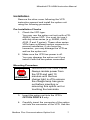
Some important features of this option unit include:
Data rate of 1 Modbus Plus
Support for up to 32 nodes without a repeater
(64 nodes with a repeater) on a single network
Network access to all VFD parameters
Passed Modicon Conformance Test
in March, 1999
Designed and assembled in the U.S.A.
Modbus Plus Communications Option Unit
i
Mitsubishi FR-A5NM Instruction Manual
This page is intentionally left blank.
Modbus Plus Communications Option Unit
ii
Mitsubishi FR-A5NM Instruction Manual
Table of Contents
Introduction ................................................... i
Table of Contents ........................................iii
List of Figures ............................................. iv
Safety Instructions ....................................... 1
Warning Information ................................ 1
Caution Information ................................. 1
Electric Shock Prevention........................ 2
Injury Prevention...................................... 3
Additional Instructions ................................. 4
Transportation and Installation ................ 4
Usage ...................................................... 4
Maintenance, Inspection, and Parts
Replacement ........................................... 5
Disposal ................................................... 5
General Information................................. 5
Structure ...................................................... 6
Installation.................................................... 7
Pre-Installation Checks ........................... 7
Mounting Procedure ................................ 7
Connecting to the Network .................... 10
Diagnostic LED Status Indicator............ 13
Operation ................................................... 15
Operating Modes ................................... 15
Selecting the Operating Mode............... 15
Functions Available in the Operating Modes
............................................................... 17
Input From Modbus Plus to VFD ........... 17
Accessing A500(L) Drive Data .................. 18
Modbus Plus Communications Option Unit
iii
Mitsubishi FR-A5NM Instruction Manual
Parameter Definitions ................................ 19
Output From VFD to Modbus Plus ........ 20
System Environment Variable (SEV) Interface
............................................................... 20
Using the Modsoft MSTR Block ............ 21
Real-Time Monitor ................................. 22
Input/Output Terminal Assignment........ 23
Operation When an Alarm Occurs ........ 24
Alarm History ......................................... 24
Alarm Numbers vs. Alarm Codes .......... 25
Normal Parameter Area......................... 26
900f Parameter Area ............................. 37
900 Percent Parameter Area................. 37
Prog Op Time (t) Components .............. 38
Prog Op Dir. (D) Components ............... 39
Prog Op Freq. (f) Components .............. 40
References ................................................ 41
Mitsubishi Electric.................................. 41
Schneider Automation ........................... 41
Technical Support Number.................... 41
Specifications ............................................ 42
Revisions ................................................... 42
Index .......................................................... 43
You will find a documentation evaluation form at the
end of the Index, following
page 46.
List of Figures
Figure 1: Top view..................................... 6
Figure 2: 3-D view ..................................... 6
Figure 3: Installation view .......................... 9
Figure 4: Mitsubishi VFD view ................... 9
Modbus Plus Communications Option Unit
iv
Mitsubishi FR-A5NM Instruction Manual
This page is intentionally left blank.
Modbus Plus Communications Option Unit
v
Mitsubishi FR-A5NM Instruction Manual
Safety Instructions
Do not attempt to install, operate, maintain, or
inspect this product until you have read through
this instruction manual and appended
documents carefully and can use the equipment
correctly. Do not use this product until you have
a full knowledge of the equipment, safety
information, and instructions.
In this manual, the safety instruction levels are
classified into WARNING and CAUTION
instructions (as described below).
Warning Information
WARNING
Denotes that incorrect
handling may cause
hazardous conditions,
resulting in death or
severe injury.
Caution Information
CAUTION
Denotes that incorrect
handling may cause
hazardous conditions,
resulting in medium or slight
injury, or may cause
physical damage only.
Note that even the CAUTION level may lead to
a serious consequence under some
circumstances. Please follow the instructions of
both levels as they are important to personal
safety.
Modbus Plus Communications Option Unit
1
Mitsubishi FR-A5NM Instruction Manual
Electric Shock Prevention
WARNING
Do not open the front
cover while power is on
or when the VFD is
running.
When installed in a VFD,
the option module is in
close proximity to
dangerously high
voltages. All precautions
should be taken to avoid
contact with such
voltages. Only trained,
authorized personnel
should conduct
installation, wiring, and
inspection. Failure to
follow the following
guidelines may result in
injury or death.
Before starting wiring or
inspection, switch VFD
power off, wait for at
least 10 minutes and
until the bus charge light
is off, and check for any
residual voltage with
appropriate test
equipment. See the FRA500(L) VFD Instruction
Manual for further
information.
Do not subject the cables
to scratches, excessive
stress, heavy loads, or
pinching.
Modbus Plus Communications Option Unit
2
Mitsubishi FR-A5NM Instruction Manual
Injury Prevention
CAUTION
Apply only the voltage
specified in the
instruction manual to
each terminal to prevent
damage, etc.
Ensure that the cables
are connected to the
correct terminals.
Otherwise damage, etc.
may occur.
Always make sure that
polarity is correct to
prevent damage, etc.
While power is on or for
some time after poweroff, do not touch the VFD
as it is hot and you may
get burnt.
Modbus Plus Communications Option Unit
3
Mitsubishi FR-A5NM Instruction Manual
Additional Instructions
Also note the following points to prevent an
accidental failure, injury, electric shock, etc.
Transportation and Installation
CAUTION
Do not install or operate
the option unit if it is
damaged or has parts
missing.
Do not stand or rest
heavy objects on the
product.
Check that the mounting
orientation is correct.
Prevent screws, metal
fragments, conductive
bodies, oil, or other
flammable substances
from entering the VFD.
Usage
Do not modify the equipment.
WARNING
CAUTION
The option module is
sensitive to electro-static
discharge. Proper ESD
measures required.
Modbus Plus Communications Option Unit
4
Mitsubishi FR-A5NM Instruction Manual
Maintenance, Inspection,
and Parts Replacement
Do not test the equipment
with a megaohm meter.
CAUTION
.
Disposal
Dispose of this product as
general industrial waste.
CAUTION
General Information
All illustrations given in this manual may have
been drawn with covers or safety guards
removed to provide in-depth descriptions.
WARNING
Before starting operation of
the product, always return
the covers and guards into
original positions as
specified and operate the
equipment in accordance
with the manual.
Modbus Plus Communications Option Unit
5
Mitsubishi FR-A5NM Instruction Manual
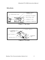
Structure
Figure 1: Top view
Figure 2: 3-D view
Modbus Plus Communications Option Unit
6
Mitsubishi FR-A5NM Instruction Manual
Installation
Remove the drive cover following the VFD
instruction manual and install the option unit
using the following procedure:
Pre-Installation Checks
1. Check the VFD type.
You may use the option unit only with a FRA500(L) series VFD. You must not use it
with any other series (e.g. A200E, A200,
A100, Z and F series). These other series
VFDs have a different option connector to
prevent installation; if you force the
connector, you may damage the VFD as
well as the option unit.
2. Make sure the VFD line power is off.
You may damage the option unit if you
install it with the line power connected.
Mounting Procedure
HAZARDOUS VOLTAGE PRESE
WARNING
Always isolate power from
the VFD and wait 10
minutes until the bus
charge light is off to ensure
the charge lamp has gone
out before inserting or
removing this option unit or
touching the terminals.
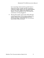
3. Insert this option unit into the VFD’s
OPTION PORT# 3 only.
4. Carefully insert the connector of the option
unit into the connector of the VFD. Use the
Modbus Plus Communications Option Unit
7
Mitsubishi FR-A5NM Instruction Manual
two mounting holes and the guide hole to
align the bottom board with the matching
machine screw inserts and the plastic guide
pin on the VFD. Make sure that the VFD
option is firmly seated in the VFD and the
connector is fully plugged in.
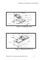
5. Secure the option unit to the VFD with two
mounting screws. If the screw holes in the
option unit do not line up with the VFD
mounting holes, check that the connectors
have been fitted correctly.
Modbus Plus Communications Option Unit
8
Mitsubishi FR-A5NM Instruction Manual
!"#
$%%&'
'
&&()*+&
-(.%&
-(
&'
,
Figure 3: Installation view
-(.%&
"
,&((
('*
.%&1*
/
&&%0
&%)&%
')&%
Figure 4: Mitsubishi VFD view
Modbus Plus Communications Option Unit
9
Mitsubishi FR-A5NM Instruction Manual
6. When making a cable for the Modbus Plus
protocol, make sure that each end of the
cable is terminated with the A5MBKT185
terminator connectors. For nodes between
the termination points, use the in-line
connectors (A5MBKT085). The cable should
be a Modbus Plus standard cable
(490NAA271xxF).
Connect a wire from the ground terminal on
the FR-A5NM to the VFD Chassis to ensure
proper grounding of the option board.
Makers of DB9 connectors, Schneider
Automation:
End Connector Part#: AS-MBKT-185 (light
gray)
Inline Connector Part#: AS-MBKT-085 (dark
gray)
7. Please consult and adhere to standard
Modbus Plus documentation and
specifications on the wiring and installation of
Modbus Plus network hardware, as provided
by Schneider Automation.
8. Set the address before placing the cover back
onto the option card.
9. Next remove the option data port insert from
the VFD cover. Then replace the VFD cover,
while making sure that the Modbus Plus
connector is aligned with the option data port
window. Connect the Modbus Plus cable to
the VFD by plugging DB9-style male
connector into DB9-style female connector of
the option unit, which should be visible in the
option port window.
Connecting to the Network
1. Make sure that the VFD power is off and the
option unit is mounted in the VFD. Connect
the Modbus Plus cable you created to the
network.
Modbus Plus Communications Option Unit
10
Mitsubishi FR-A5NM Instruction Manual
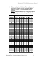
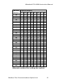
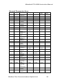
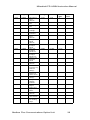
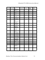
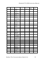
2. When setting the Modbus Plus address on
the option board, use the following table.
Refer to Figure 1 for the address switch
location.
NOTE: A switch setting of 1 indicates the On
position, and a switch setting of 0 indicates
the Off position.
Decimal
Switch Positions
Address
3
4
5
6
7
8
9
10
11
12
13
14
15
16
17
18
19
20
21
22
23
24
25
26
27
28
29
30
31
1
1
0
1
0
1
0
1
0
1
0
1
0
1
0
1
0
1
0
1
0
1
0
1
0
1
0
1
0
1
2
0
0
1
1
0
0
1
1
0
0
1
1
0
0
1
1
0
0
1
1
0
0
1
1
0
0
1
1
0
3
1
1
0
0
0
0
1
1
1
1
0
0
0
0
1
1
1
1
0
0
0
0
1
1
1
1
0
0
0
4
1
1
1
1
1
1
0
0
0
0
0
0
0
0
1
1
1
1
1
1
1
1
0
0
0
0
0
0
0
5
1
1
1
1
1
1
1
1
1
1
1
1
1
1
0
0
0
0
0
0
0
0
0
0
0
0
0
0
0
Modbus Plus Communications Option Unit
6
1
1
1
1
1
1
1
1
1
1
1
1
1
1
1
1
1
1
1
1
1
1
1
1
1
1
1
1
1
7
1
1
1
1
1
1
1
1
1
1
1
1
1
1
1
1
1
1
1
1
1
1
1
1
1
1
1
1
1
8
1
1
1
1
1
1
1
1
1
1
1
1
1
1
1
1
1
1
1
1
1
1
1
1
1
1
1
1
1
11
Mitsubishi FR-A5NM Instruction Manual
Decimal
Switch Positions
Address
32
33
34
35
36
37
38
39
40
41
42
43
44
45
46
47
48
49
50
51
52
53
54
55
56
57
58
59
60
61
62
63
1
0
1
0
1
0
1
0
1
0
1
0
1
0
1
0
1
0
1
0
1
0
1
0
1
0
1
0
1
0
1
0
1
2
0
1
1
0
0
1
1
0
0
1
1
0
0
1
1
0
0
1
1
0
0
1
1
0
0
1
1
0
0
1
1
0
3
0
1
1
1
1
0
0
0
0
1
1
1
1
0
0
0
0
1
1
1
1
0
0
0
0
1
1
1
1
0
0
0
4
0
1
1
1
1
1
1
1
1
0
0
0
0
0
0
0
0
1
1
1
1
1
1
1
1
0
0
0
0
0
0
0
5
0
1
1
1
1
1
1
1
1
1
1
1
1
1
1
1
1
0
0
0
0
0
0
0
0
0
0
0
0
0
0
0
6
1
0
0
0
0
0
0
0
0
0
0
0
0
0
0
0
0
0
0
0
0
0
0
0
0
0
0
0
0
0
0
0
7
1
1
1
1
1
1
1
1
1
1
1
1
1
1
1
1
1
1
1
1
1
1
1
1
1
1
1
1
1
1
1
1
8
1
1
1
1
1
1
1
1
1
1
1
1
1
1
1
1
1
1
1
1
1
1
1
1
1
1
1
1
1
1
1
1
Alternate method for setting the switch:
Modbus Plus Communications Option Unit
12
Mitsubishi FR-A5NM Instruction Manual
To set the node address to be nn, first
subtract 1 from it.
Convert the result (nn-1) into hexadecimal
XXh.
Then span it into binary format, padding with
0’s in the front 00fedcba.
Finally, take the complement 11nmlkji, if a
bit is 0, set the switch to Off position; if a bit
is 1, set the switch to On position.
NOTE: the first two leading position switches
are not used.
For example, to set the node address to 30, do the
following:
Convert the result 29=30-1 into 1Dh
Span into 8-bit format 00011101
Take the complement 11100010
Set 8 positions according to c
3. It is now safe to apply power to the VFD and
run it in PU, external, or net mode, provided
that any external VFD control cables in
addition to the Modbus Plus network cable
are installed correctly.
Diagnostic LED Status Indicator
The green LED located next to the address DIP
switch on the Modbus Plus option top board
provides indication of communication status. The
LED on the bottom board will be solid green if the
option CPU acts correctly.
The following describes the LED on the top board
definitions.
Green
State of system
Flash every 160 mSec
Node is working normally.
Modbus Plus Communications Option Unit
13
Mitsubishi FR-A5NM Instruction Manual
It is successfully receiving
and passing the network
token.
Flash every 1 Sec
Node is in the
MONITOR_OFFLINE
state. It monitors the
network link every
5 seconds but is not
transmitting.
2 flashes, off 2 Secs
Node is in MAC_IDLE
state. This node may
have a bad transmitter.
3 flashes, off 1.7 Secs
Node is not receiving
tokens. This indicates that
this node is the only
active node on the
network or the receiver is
bad.
4 flashes, off 1.4 Secs
Duplicate node address
seen.
Modbus Plus Communications Option Unit
14
Mitsubishi FR-A5NM Instruction Manual
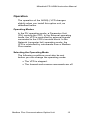
Operation
The operation of the A500(L) VFD changes
slightly when you install this option unit, as
described below.
Operating Modes
In the PU operating mode, a Parameter Unit
(PU) controls the VFD. In the External-operating
mode, the VFD is controlled by external signals
connected to the VFD’s terminal block. In the
Network (computer link) operating mode, the
VFD is controlled by commands from a Modbus
Plus master.
Selecting the Operating Mode
The following conditions must also be met
before you can change the operating mode:
The VFD is stopped.
The forward and reverse commands are off.
Modbus Plus Communications Option Unit
15
Mitsubishi FR-A5NM Instruction Manual
The following table describes the actions required to
change the operating mode.
Mode Change
Action
Required
Ext Operation => PU Operation
User presses
PU key on
Parameter Unit.
PU Operation => Ext Operation
User presses
EXT key on
Parameter Unit.
Ext Operation => Net Operation
Modbus Plus
master writes a
1400h to
Register 40010.
Net Operation => Ext Operation
Modbus Plus
master writes a
1000h to
Register 40010.
For all other mode changes, please refer to the
FR-A500(L) VFD Instruction Manual.
Pr 340 allows you to select the Network operating
mode on power-up and after a drive reset. Once
the Network operating mode is initiated, there must
be Modbus Plus activity at least once every 3
seconds. If the option unit does not sense valid
Modbus Plus activity for 3 seconds or more, the
VFD performs an option module alarm stop
(E.OP3), and
you must reset the VFD to clear this fault.
Modbus Plus Communications Option Unit
16
Mitsubishi FR-A5NM Instruction Manual
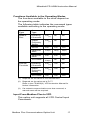
Functions Available in the Operating Modes
The functions available to the drive depend on
the operating mode.
The following table indicates the command types
available according to the operating mode.
Control
Type
Command
Type
Net
Ext
PU
Modbus
Plus
Operating
Command
Yes(1)
No
No
Output
Frequency
Setting
Yes(1)
No
No
Monitor
Yes
Yes
Yes
Parameter
Write
Yes(2)
No(2)
No(2)
Parameter
Read
Yes
Yes
Yes
VFD Reset
Yes(3)
No
No
Operating
Command
Yes(1)
Yes
No
Output
Frequency
Setting
Yes(1)
Yes
No
VFD Reset
Yes
Yes
Yes
External
Terminals
(1)
Depends on the value of Prs 338 and 339.
(2)
Depends on the value set in Pr 77.
Refer to the FR-A500(L) VFD Instruction Manual for
further information.
(3)
If a network communication error has occurred, a
manual reset will be required.
Input From Modbus Plus to VFD
This option unit supports all VFD Control Input
Commands.
Modbus Plus Communications Option Unit
17
Mitsubishi FR-A5NM Instruction Manual
Accessing A500(L) Drive Data
1. This option unit acts as a Modbus Plus slave
to a PLC or equivalent controller acting as a
Modbus Plus master.
This means that the option unit:
Acknowledges messages received
Transmits messages at the request of a
network master.
2. The option unit can also act as a Modbus
Plus slave to a Modbus Plus master that can
read the drive’s I/O values, as well as
configure the drive itself.
3. The option unit cannot send messages on
its own, and it has no bus access rights. It
also cannot simultaneously act as a slave to
network master and as a lead drive (master)
to follower drives (slaves).
4. This option unit does not support any other
manufacturer-specific messages or
parameters.
Modbus Plus Communications Option Unit
18
Mitsubishi FR-A5NM Instruction Manual
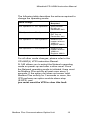
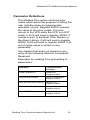
Parameter Definitions
The Modbus Plus option card has error
codes which serve the purpose of letting the
user indicate when an inappropriate
operation occurs. Register 40020 contains
the value of the error codes. If a write
occurs to the VFD while the VFD is in EXT
mode, a 0x14 will exist in register 40020. If
a write occurs to the Real Time Monitor or
the Alarm History, 0x42 will exist in register
40020. 0x43 will exist in register 40020 if an
out of range value is written to any
parameter.
Any register that does not appear in any
entry of the following tables is considered
Reserved.
Examples for reading from and writing to
parameters:
Operation
Communication
Function
Read Parameter 0
Read from
Register 41000
Start running forward
Write a 2 Decimal to
Register 40009
Stop the drive from running
Write a 0 to
Register 40009
Enable Net Mode
Write a 0x14 to
Register 40010
Enable EXT Mode
Write a 0x10 to
Register 40010
Modbus Plus Communications Option Unit
19
Mitsubishi FR-A5NM Instruction Manual
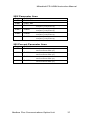
Output From VFD to Modbus Plus
To check the VFD status, read the word out from
Register 40009.
The following table describes the
bit-map for the VFD status word.
Bit
Definition
Abbreviation
0
1
2
3
4
5
6
7
8-14
1 = running
1 = forward running
1 = reverse running
1 = up to frequency
1 = overload
1 = instantaneous power failure
1 = frequency detection
1 = alarm
Special
(RUN)
(FWD)
(REV)
(SU)
(OL)
(IPF)
(FU)
(ABC)
System Environment Variable (SEV) Interface
VFD
Reg
40001
40002
40003
40004
40005
40006
40007
40008
40009
40010
Definition
Access
WriteVal
UsrClrValSett
VFDReset
PrClr
PrAllClr
PrUsrClr
PrClr(ECP)
PrAllClr(ECP)
PrUsrClr(ECP)
VFDStatus/CtrlInpCmd
OpMode/VFDConfig
WO
WO
WO
WO
WO
WO
WO
WO
R/W
R/W
40013
40014
40015
f Sett Val
Runng f (RAM) #
Runng f (EEPROM) #
R/W
R/W
WO
0000h
0000h
5A96h
AA99h
555Ah
965Ah
99Aah
5A55h
XX00h
Ext=1000h
Net=1400h
ggffh
ggffh
ggffh
WO: Write only, no read.
(1)
Writing to Register 40014 or 40015 can be read out
from Register 40014.
Modbus Plus Communications Option Unit
20
Mitsubishi FR-A5NM Instruction Manual
Using the Modsoft MSTR Block
Items in the above table are byte-swapped. This
means, for example, that to place the VFD in
“net mode” a value of 0014H should be written
to register 40010 in the VFD instead of the
1400H value shown.
The MSTR control register usage is as follows:
PLC
Register
n
Registe
r Value
Value
Base
Description
1,2
decimal
n+1
xxxx
n+2
1
hexadecimal
decimal
n+3
rrrr
decimal
n+4,
5,
6,
7
node
number
decimal
Commands MSTR
function:
1 = write; 2 = read
MSTR function error
code
Number of registers
to be written/read to
/from the VFD
Specifies the VFD
register to write/read
to/from. Value
represents an offset
starting w/register
40000 (i.e. 1 =
40001; 49 = 40049).
Routing registers
contain Modbus Plus
nodes for
communication
routing. The first
register following the
register containing
the VFD node
number must
contain a 1 value.
Remaining routing
registers must
contain a 0 value.
Modbus Plus Communications Option Unit
21
Mitsubishi FR-A5NM Instruction Manual
Real-Time Monitor
Reg
40201
40202
40203
40205
40206
40207
40208
40209
40210
40211
40212
40213
40214
40215
40216
40217
40218
40219
40220
40222
40223
40224
40225
Definition
RTM01 Outp f
RTM02 Outp I
RTM03 Outp V
RTM05 f Sett Val
RTM06 Runng Spd
RTM07 Motor Torq
RTM08 Convrtr Outp V
RTM09 Regen Brake Duty
RTM10 Electr Overcur
Protectn Load Factr
RTM11 Outp I Peak
RTM12 VFD Peak Outp V
RTM13 VFD Input Powr
RTM14 VFD Output Powr
RTM15 Inp Termnl Status
RTM16 Outp Termnl Status
RTM17 Load Meter
RTM18 Motor Excitatn I
RTM19 Positive Pulse
RTM20 Cumulative Energ t
RTM22 Orientatn Status
RTM23 Actl Op t
RTM24 Motor Load Factr
RTM25 Cumulative Powr
Prec.
0.01Hz
0.01A
0.1V
0.01Hz
1r/m
0.1%
0.1V
0.1%
0.1%
0.01A
0.1V
0.01kW
0.01kW
0.01A
1h
1h
0.1%
1kWh
Bit-Map for Register 40215
Input Terminal Monitor:
15..12
0
5
RM
11
CS
4
RL
10
RES
3
RT
9
STOP
2
AU
1
STR
8
MRS
7
JOG
6
RH
0
STF
Modbus Plus Communications Option Unit
22
Mitsubishi FR-A5NM Instruction Manual
Bit-Map for Register 40216
Outp Terminal Monitor:
15..6
0
NOTE:
5
Relay
4
FU
3
OL
2
IPF
1
SU
0
RUN
The bit-wise data here reflect Prs 190-196; if
assignments for terminals are changed, the bit-map
may not be the same.
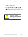
Input/Output Terminal Assignment
CAUTION
Input/output terminal
assignment functions depend
upon programmed functions
such as brake sequences
Modbus Plus Communications Option Unit
23
Mitsubishi FR-A5NM Instruction Manual
Operation When an Alarm Occurs
The following table shows the behavior of the
VFD and network when an alarm occurs:
Fault
Type
Item
Net
Ext
PU
VFD
VFD
Operation
Stop
Stop
Stop
Continue
Continue
Network
Comm.
Continue
VFD
Operation
Stop
Continue
Continue
Continue (1)
Continue (1)
Modbus
Plus
Comm.
Network
Comm
(1)
Continue (1)
Depends on the type of communication fault.
Alarm History
Reg
Definition
40501
Alarm 1(1)
40502
Alarm 2
40503
Alarm 3
40504
Alarm 4
40505
Alarm 5
40506
Alarm 6
40507
Alarm 7
40508
Alarm 8
(1)
Writing a value of 0000h to this parameter resets the
alarm history buffer for all alarms. All other entries in
this table are read only.
Modbus Plus Communications Option Unit
24
Mitsubishi FR-A5NM Instruction Manual
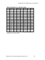
Alarm Numbers vs. Alarm Codes
#
Code
#
Code
#
Code
#
Code
10
OC1
80
GF
D1
Osd
F3
E3
11
OC2
81
LF
D2
ECT
F4
E4
12
OC3
90
OHT
D3
Od
F5
E5
20
OV1
A0
OPT
D4
ECA
F6
E6
21
OV2
A1
OP1
D5
Mb1
F7
E7
22
OV3
A2
OP2
D6
Mb2
F8
E8
30
THT
A3
OP3
D7
Mb3
F9
E9
31
THM
B0
PE
D8
Mb4
FA
E10
40
FIN
B1
PUE
D9
Mb5
FB
E11
41
FAN
B2
RET
DA
Mb6
FC
E12
50
IPF
C0
CPU
DB
Mb7
FD
E13
51
UVT
C1
CTE
F0
E0
FE
E14
60
OLT
C2
P24
F1
E1
FF
E15
70
BE
D0
OS
F2
E2
Please refer to the FR-A500(L) VFD Instruction Manual for an
explanation of Alarm Codes.
Modbus Plus Communications Option Unit
25
Mitsubishi FR-A5NM Instruction Manual
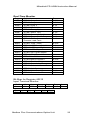
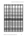
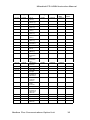
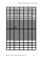
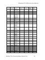
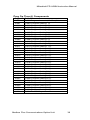
Normal Parameter Area
Pr
Reg
Definition
Range
Hex
A500
Prec
Pr0
41000
Torq Boost
(Manual)
0-30
0-12C
0.1%
Pr1
41001
Max f Limit
0-120
0-2EE0
0.01Hz
Pr2
41002
Min f Limit
0-120
0-2EE0
0.01Hz
Pr3
41003
Base f Limit
0-400
0-9C40
0.01Hz
Pr4
41004
MultiSpd Set
(HiSpd)
0-400
0-9C40
0.01Hz
Pr5
41005
MultiSpd Set
(MiSpd)
0-400
0-9C40
0.01Hz
Pr6
41006
MultiSpd Set
(LoSpd)
0-400
0-9C40
0.01Hz
Pr7
41007
Acc t
0-3600
0-8CA0
0.1s
Pr8
41008
Dec t
0-3600/
0-360
0-8CA0
0.1s/
0.01s
Pr9
41009
Electr
Therml O/L
Relay
0-500
0-C350
0.01A
Pr10
41010
DC Inj Brake
Op f
0-120
0-2EE0
0.01Hz
Pr11
41011
DC Inj
Brake Op t
0-10
0-64
0.1s
Pr12
41012
DC Inj
Brake V
0-30
0-12C
0.1%
Pr13
41013
Startg f
0-60
0-1770
0.01Hz
Pr14
41014
Applied
Load
Pattern
0-5
0-5
1
Pr15
41015
Jog f
0-400
0-9C40
0.01Hz
Pr16
41016
Jog
Acc/Dec t
0-3600/
0-360
0-8CA0
0.1s/
0.01s
Pr17
41017
MRS Inp
Selectn
0-3
0-3
1
Pr18
41018
HiSpd Max f
Limit
120-400
2EE09C40
0.01Hz
Pr19
41019
Base f V
0-1000
0-2710
0.1V
Pr20
41020
Acc/Dec
Ref f
0-400
0-9C40
0.01Hz
Pr21
41021
Acc/Dec t
Increments
0-1
0-1
1
Pr22
41022
Stall
Preventn
Op Level
0-200
0-7D0
0.1%
Pr23
41023
Stall
Preventn
Op Level
At
DoubleSpd
0-200
0-7D0
0.1%
Pr24
41024
MultiSpd Set
(Spd4)
0-400
0-9C40
0.01Hz
Pr25
41025
MultiSpd Set
(Spd5)
0-400
0-9C40
0.01Hz
Modbus Plus Communications Option Unit
A500L
Prec
26
Mitsubishi FR-A5NM Instruction Manual
Pr
Reg
Definition
Range
Hex
A500
Prec
Pr26
41026
MultiSpd Set
(Spd6)
0-400
0-9C40
0.01Hz
Pr27
41027
MultiSpd Set
(Spd7)
0-400
0-9C40
0.01Hz
Pr28
41028
MultiSpd Inp
Compensatn
0-1
0-1
1
Pr29
41029
Acc/Dec
Pattern
0-3
0-3
1
Pr30
41030
Regen Func
Selectn
0-2
0-2
0
Pr31
41031
f Jump 1A
0-400
0-9C40
0.01Hz
Pr32
41032
f Jump 1B
0-400
0-9C40
0.01Hz
Pr33
41033
f Jump 2A
0-400
0-9C40
0.01Hz
Pr34
41034
f Jump 2B
0-400
0-9C40
0.01Hz
Pr35
41035
f Jump 3A
0-400
0-9C40
0.01Hz
Pr36
41036
f Jump 3B
0-400
0-9C40
0.01Hz
Pr37
41037
Spd Display
2-9998
2-270E
1
41038
Special
41039
Special
41040
Special
Pr41
41041
Up-To-f
Sensitvty
0-1000
0-3E8
0.1%
Pr42
41042
Outp f
Detectn
0-400
0-9C40
0.01Hz
Pr43
41043
Outp f
Detectn At
REV Rotatn
0-400
0-9C40
0.01Hz
Pr44
41044
2nd
Acc/Dec t
0-3600/
0-360
0-8CA0
0.1s/
0.01s
Pr45
41045
2nd Dec t
0-3600/
0-360
0-8CA0
0.1s/
0.01s
Pr46
41046
2nd Torq
Boost
0-30
0-12C
0.1%
Pr47
41047
2nd V/F
(Base f)
0-400
0-9C40
0.01Hz
Pr48
41048
2nd Stall
Preventn
Op I
0-200
0-7D0
0.1%
Pr49
41049
2nd Stall
Preventn
Op f
0-400
0-9C40
0.01Hz
Pr50
41050
2nd Outp f
Detectn
0-400
0-9C40
0.01Hz
41051
Special
Pr52
41052
PU Main
Display Data
Selectn
0-20
0-18
1
Pr53
41053
PU Level
Display Data
Selectn
0-18
0-12
1
Modbus Plus Communications Option Unit
A500L
Prec
27
Mitsubishi FR-A5NM Instruction Manual
Pr
Reg
Definition
Range
Hex
A500
Prec
Pr54
41054
FM Termnl
Func
Selectn
1-121
1-79
1
Pr55
41055
f Monitorg
Ref
0-400
0-9C40
0.01Hz
Pr56
41056
I Monitorg
Ref
0-500
0-C350
0.01Hz
Pr57
41057
Restart
Coastg t
0-5
0-32
0.1s
Pr58
41058
Restart
Cushion t
0-5
0-32
0.1s
Pr59
41059
Remote Sett
Func
Selectn
0-2
0-2
1
Pr60
41060
Intellgnt
Mode
Selectn
0-6
0-6
1
Pr61
41061
Ref I For
Intellgnt
Mode
0-500
0-C350
0.01A
Pr62
41062
Ref I For
Intellgnt
Mode Acc
0-200
0-7D0
0.1%
Pr63
41063
Ref I For
Intellgnt
Mode Dec
0-200
0-7D0
0.1%
Pr64
41064
Startg f For
Elevator
Mode
0-10
0-3E8
0.01Hz
Pr65
41065
Retry
Selectn
0-5
0-5
1
Pr66
41066
Stall
Preventn Op
Reductn
Startg f
0-400
0-9C40
0.01Hz
Pr67
41067
No. Of
Retries At
Alarm Occur
0-10
0-A
1
Pr68
41068
Retry
Waitg t
0-10
0-64
0.1s
Pr69
41069
Retry Count
Display
Erasure
0
0
1
Pr70
41070
Special
Regen
Brake Duty
0-30
0-12C
0.1%
Pr71
41071
Applied
Motor
0-20
0-14
1
Pr72
41072
PWM f
Selectn
0.7-14.5
7-91
0.1kHz
Pr73
41073
0 to 5V, 0 to
10V Selectn
0-15
0-F
1
Pr74
41074
Response t
For Analog
Signl
0-8
0-8
1
Modbus Plus Communications Option Unit
A500L
Prec
28
Mitsubishi FR-A5NM Instruction Manual
Pr
Reg
Definition
Range
Hex
A500
Prec
Pr75
41075
Reset/
Disconnectd
PU Detectn/
PU Stop
Selectn
0-17
0-11
1
Pr76
41076
Alarm Code
Outp
Selectn
0-3
0-3
1
Pr77
41077
Pr Write
Disable
Selectn
0-2
0-2
1
Pr78
41078
REV Rotatn
Preventn
Selectn
0-2
0-2
1
Pr79
41079
Op Mode
Selectn
0-8
0-8
1
Pr80
41080
Motor
Capacity
.4-55
28-157C
0.01k
W
Pr81
41081
No. Of
Motor Poles
2-16
2-10
1
Pr82
41082
Excitatn I
0-9999
0-270F
0.01A
Pr83
41083
Rated
Motor V
0-1000
0-2710
0.1V
Pr84
41084
Rated
Motor f
50-120
13882EE0
0.01Hz
41085
Special
41086
Special
41087
Special
41088
Special
41089
Special
Pr90
41090
Motor
Constant R1
0-9999
0-270F
0.01
Pr91
41091
Motor
Constant R2
0-9999
0-270F
0.01
Pr92
41092
Motor
Constant L1
0-9999
0-270F
0.01
Pr93
41093
Motor
Constant L2
0-9999
0-270F
0.01
Pr94
41094
Motor
Constant X
0-9999
0-270F
0.01
Pr95
41095
Online Auto
Tung
0-1
0-1
1
Pr96
41096
Autotung
Set/State
0-101
0-65
1
41097
Special
41098
Special
41099
Special
Pr100
41100
V/F 1
(1st f)
0-400
0-9C40
0.01Hz
Pr101
41101
V/F 1
(1st f V)
0-1000
0-2710
0.1V
Modbus Plus Communications Option Unit
A500L
Prec
29
Mitsubishi FR-A5NM Instruction Manual
Pr
Reg
Definition
Range
Hex
A500
Prec
Pr102
41102
V/F 2
(2nd f)
0-400
0-9C40
0.01Hz
Pr103
41103
V/F 2
(2nd f V)
0-1000
0-2710
0.1V
Pr104
41104
V/F 3 (3rd f)
0-400
0-9C40
0.01Hz
Pr105
41105
V/F 3
(3rd f V)
0-1000
0-2710
0.1V
Pr106
41106
V/F 4
(4th f)
0-400
0-9C40
0.01Hz
Pr107
41107
V/F 4
(4th f V)
0-1000
0-2710
0.1V
Pr108
41108
V/F 5
(5th f)
0-400
0-9C40
0.01Hz
Pr109
41109
V/F 5
(5th f V)
0-1000
0-2710
0.1V
Pr110
41110
3rd
Acc/Dec t
0-3600
0-8CA0
0.1s
Pr111
41111
3rd Dec t
0-3600
0-8CA0
0.1s
Pr112
41112
3rd Torq
Boost
0-30
0-12C
0.1%
Pr113
41113
3rd V/F
(Base f)
0-400
0-9C40
0.01Hz
Pr114
41114
3rd Stall
Preventn
Op I
0-200
0-7D0
0.1%
Pr115
41115
3rd Stall
Preventn
Op f
0-400
0-9C40
0.01Hz
Pr116
41116
3rd Outp f
Detectn
0-400
0-9C40
0.01Hz
Pr117
41117
Statn No.
0-31
0-1F
1
Pr118
41118
Comms Spd
48-192
30-C0
1
Pr119
41119
Stop Bit
Length
0-11
0-B
1
Pr120
41120
Parity Chk
Presence
/Absence
0-2
0-2
1
Pr121
41121
No. Of
Comms
Retries
0-10
0-A
1
Pr122
41122
Comms
Chk t
Interval
0-999.8
0-270E
0.1s
Pr123
41123
Waitg t Sett
0-150
0-96
1ms
Pr124
41124
CR,LF
Presence
/Absence
Selectn
0-2
0-2
1
41125
Special
41126
Special
41127
Special
41128
PID Actn
Selectn
10-21
A-15
1
Pr128
Modbus Plus Communications Option Unit
A500L
Prec
30
Mitsubishi FR-A5NM Instruction Manual
Pr
Reg
Definition
Range
Hex
A500
Prec
Pr129
41129
PID
Proportionl
Band
0-1000
0-2710
0.1%
Pr130
41130
PID Integrl t
0.1-3600
1-8CA0
0.1s
Pr131
41131
PID Uppr
Limit
0-100
0-3E8
0.1%
Pr132
41132
PID Lowr
Limit
0-100
0-3E8
0.1%
Pr133
41133
PID Actn
Set Pnt For
PU Op
0-100
0-3E8
0.1%
Pr134
41134
PID
Differentl t
0.01-10
1-3E8
0.01s
Pr135
41135
CPS-VFD
Swc-Over
Seq
Outp Termnl
Selectn
0-2
0-2
1
Pr136
41136
MC
Swc-Over
Interlock t
0-100
0-3E8
0.1s
Pr137
41137
Startg
Waitg t
0-100
0-3E8
0.1s
Pr138
41138
CPS-VFD
Swc-Over
Selectn
At Alarm
Occur
0-1
0-1
1
Pr139
41139
Auto VFDCPS
Swc-Over f
0-60
0-1770
0.01Hz
Pr140
41140
Backlash
Acc Stopg f
0-400
0-9C40
0.01Hz
Pr141
41141
Backlash
Acc Stopg t
0-360
0-E10
0.1s
Pr142
41142
Backlash
Dec Stopg f
0-400
0-9C40
0.01Hz
Pr143
41143
Backlash
Dec Stopg t
0-360
0-E10
0.1s
Pr144
41144
Spd Sett
Swc-Over
0-110
0-6E
1
41145
PU Lang
Swc
0-7
0-7
1
41146
Special
41147
Special
Pr148
41148
Stall
Preventn
Level
At 0V Inp
0-200
0-7D0
0.1%
Pr149
41149
Stall
Preventn
Level
At 10V Inp
0-200
0-7D0
0.1%
Pr145
Modbus Plus Communications Option Unit
A500L
Prec
31
Mitsubishi FR-A5NM Instruction Manual
Pr
Reg
Definition
Range
Hex
A500
Prec
Pr150
41150
Outp I
Detectn
Level
0-200
0-7D0
0.1%
Pr151
41151
Outp I
Detectn
Period
0-10
0-64
0.1s
Pr152
41152
0-I Detectn
Level
0-200
0-7D0
0.1%
Pr153
41153
0-I Detectn
Period
0-1
0-64
0.01s
Pr154
41154
V Reductn
Selectn
During Stall
Preventn Op
0-1
0-1
1
Pr155
41155
RT Activatd
Cond
0-10
0-A
1
Pr156
41156
Stall
Preventn Op
Selectn
0-100
0-64
1
Pr157
41157
OL Sgnl
Waitg t
0-25
0-FA
0.1s
Pr158
41158
AM Termnl
Func
Selectn
1-21
1-15
1
41159
Special
41160
Usr Group
Read
Selectn
0-11
0-B
1
Pr160
41161
Special
Pr162
41162
Auto Restart
After IPF
Selectn
0-1
0-1
1
Pr163
41163
1st Cushn t
For Restart
0-20
0-C8
0.1s
Pr164
41164
1st Cushn V
For Restart
0-100
0-3E8
0.1s
Pr165
41165
Restart Stall
Preventn Op
Level
0-200
0-7D0
0.1s
41166
Special
41167
Special
41168
Special
41169
Special
Pr170
41170
Watt-Hr
Meter Clr
0
0
1
Pr171
41171
Actl Op Hr
Meter Clr
0
0
1
41172
Special
Pr173
41173
Usr Group 1
Registratn
0-999
0-3E7
1
Pr174
41174
Usr Group 1
Deletn
0-999
0-3E7
1
Pr175
41175
Usr Group 2
Registratn
0-999
0-3E7
1
Modbus Plus Communications Option Unit
A500L
Prec
32
Mitsubishi FR-A5NM Instruction Manual
Pr
Reg
Definition
Range
Hex
A500
Prec
Pr176
41176
Usr Group 2
Deletn
0-999
0-3E7
1
41177
Special
41178
Special
41179
Special
Pr180
41180
RL Termnl
Func
Selectn
0-99
0-63
1
Pr181
41181
RM Termnl
Func
Selectn
0-99
0-63
1
Pr182
41182
RH Termnl
Func
Selectn
0-99
0-63
1
Pr183
41183
RT Termnl
Func
Selectn
0-99
0-63
1
Pr184
41184
AU Termnl
Func
Selectn
0-99
0-63
1
Pr185
41185
JOG Termnl
Func
Selectn
0-99
0-63
1
Pr186
41186
CS Termnl
Func
Selectn
0-99
0-63
1
41187
Special
41188
Special
41189
Special
Pr190
41190
RUN Termnl
Func
Selectn
0-199
0-C7
1
Pr191
41191
SU Termnl
Func
Selectn
0-199
0-C7
1
Pr192
41192
IPF Termnl
Func
Selectn
0-199
0-C7
1
Pr193
41193
OL Termnl
Func
Selectn
0-199
0-C7
1
Pr194
41194
FU Termnl
Func
Selectn
0-199
0-C7
1
Pr195
41195
ABC Termnl
Func
Selectn
0-199
0-C7
1
41196
Special
41197
Special
41198
Special
Pr199
41199
Usr’s Initl
Val Sett
0-999
0-3E7
1
Pr232
41232
MultiSpd
Sett (Spd8)
0-400
0-9C40
0.01Hz
Modbus Plus Communications Option Unit
A500L
Prec
33
Mitsubishi FR-A5NM Instruction Manual
Pr
Reg
Definition
Range
Hex
A500
Prec
Pr233
41233
MultiSpd
Sett (Spd9)
0-400
0-9C40
0.01Hz
Pr234
41234
MultiSpd
Sett (Spd10)
0-400
0-9C40
0.01Hz
Pr235
41235
MultiSpd
Sett (Spd11)
0-400
0-9C40
0.01Hz
Pr236
41236
MultiSpd
Sett (Spd12)
0-400
0-9C40
0.01Hz
Pr237
41237
MultiSpd
Sett (Spd13)
0-400
0-9C40
0.01Hz
Pr238
41238
MultiSpd
Sett (Spd14)
0-400
0-9C40
0.01Hz
Pr239
41239
MultiSpd
Sett (Spd15)
0-400
0-9C40
0.01Hz
41240
Special
41241
Special
41242
Special
41243
Special
41244
Special
41245
Special
41246
Special
41247
Special
41248
Special
41249
Special
41250
Special
41251
Special
41252
Special
41253
Special
41254
Special
41255
Special
41256
Special
41257
Special
41258
Special
41259
Special
41260
Special
Pr261
41261
Power
Failure Stop
Func
0-1
0-1
1
Pr262
41262
Subtractd f
At Dec Start
0-20
0-7D0
0.01Hz
Pr263
41263
Subtractn
Startg f
0-120
0-2EE0
0.01Hz
Pr264
41264
PowerFailure
Dec t 1
0-3600
0-8CA0
0.1s
Pr265
41265
Power
Failure
Dec t 2
0-3600
0-8CA0
0.1s
Modbus Plus Communications Option Unit
A500L
Prec
34
Mitsubishi FR-A5NM Instruction Manual
Pr
Reg
Definition
Range
Hex
A500
Prec
Pr266
41266
Power
Failure Dec t
Swc-Over f
0-400
0-9C40
0.01Hz
41267
Special
41268
Special
41269
Special
Pr270
41270
Stop-OnContact/
Load Torq
HiSpd Ctrl
Selectn
0-3
0-3
1
Pr271
41271
HiSpd Sett
Max I
0-200
0-7D0
0.1%
Pr272
41272
HiSpd Sett
Min I
0-200
0-7D0
0.1%
Pr273
41273
I Avg Range
0-400
0-9C40
0.01Hz
Pr274
41274
I Avg Filter
Constant
1-4000
1-FA0
1
Pr275
41275
Stop-OnContact
Excitg I
LoSpd
Multipl Factr
0-1000
0-3E8
1%
Pr276
41276
Stop-OnContact
PWM
Carrier f
0-15
0-F
1
41277
Special
Pr278
41278
Brake
Openg f
0-30
0-BB8
0.01Hz
Pr279
41279
Brake
Openg I
0-200
0-7D0
0.1%
Pr280
41280
Brake
Openg I
Detectn t
0-2
0-14
0.1s
Pr281
41281
Brake Op t
At Start
0-5
0-32
0.1s
Pr282
41282
Brake
Closg f
0-30
0-BB8
0.01Hz
Pr283
41283
Brake Op t
At Stop
0-5
0-32
0.1s
Pr284
41284
Dec Detectn
Func
Selectn
0-1
0-1
1
Pr285
41285
Overspd
Detectn f
0-30
0-BB8
0.01Hz
41286
Special
41287
Special
41288
Special
41289
Special
41290
Special
41291
Special
41292
Special
41293
Special
Modbus Plus Communications Option Unit
A500L
Prec
35
Mitsubishi FR-A5NM Instruction Manual
Pr
Reg
Definition
Range
Hex
A500
Prec
Pr338
41338
Op Cmd
Source
0-1
0-1
1
Pr339
41339
Spd Cmd
Source
0-1
0-1
1
Pr340
41340
Link Startup
Mode
Selectn
0-2
0-2
1
41341
Special
41342
Special
41360
Special
41361
Special
41362
Special
41363
Special
41364
Special
41365
Special
41366
Special
Pr367
41367
Spd Feedbk
Range
0-400
0-9C40
0.01Hz
Pr368
41368
Feedbk
Gain
0-100
0-64
1
A500L
Prec
Notes:
1. Some default values depend on the rating of
the VFD.
2. Values of 65535 Unit, 6553.5 Unit, 655.35
Unit indicate the function is NOT active; its
meaning is the same as 9999 on PU, as
specified in the FR-A500(L) VFD Instruction
Manual.
3. Please refer to the FR-A500(L) VFD
Instruction Manual for more details.
4. Access to Special Parameters from Modbus
Plus depends on the actual functions and
option units installed.
Modbus Plus Communications Option Unit
36
Mitsubishi FR-A5NM Instruction Manual
900f Parameter Area
Reg
41900
41901
41902
Definition
Pr900 FM
Pr901 AM
Pr902f
41903
Pr903f
Frequency Setting Voltage Gain,
Frequency Component (f)
41904
Pr904f
Frequency Setting Current Bias,
Frequency Component (f)
41905
Pr905f
Frequency Setting Current Gain,
Frequency Component (f)
Terminal Calibration
Terminal Calibration
Pr902f Frequency Setting Voltage Bias,
Frequency Component (f)
900 Percent Parameter Area
Reg
42092
Definition
Pr902%
42093
Pr903%
Frequency Setting Voltage Gain,
Percent Of Full Scale (%)
42094
Pr904%
Frequency Setting Current Bias,
Percent Of Full Scale (%)
42095
Pr905%
Frequency Setting Current Gain,
Percent Of Full Scale (%)
Frequency Setting Voltage Bias
Percent Of Full Scale (%)
Modbus Plus Communications Option Unit
37
Mitsubishi FR-A5NM Instruction Manual
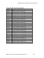
Prog Op Time (t) Components
Reg
41200
41201
41202
41203
41204
41205
41206
41207
41208
41209
41210
41211
41212
41213
41214
41215
41216
41217
41218
41219
41220
41221
41222
41223
41224
41225
41226
41227
41228
41229
41230
41231
Definition
Pr200 Program time unit (Min/Sec) Select
Pr201t Program Setting 1 (t)
Pr202t Program Setting 2 (t)
Pr203t Program Setting 3 (t)
Pr204t Program Setting 4 (t)
Pr205t Program Setting 5 (t)
Pr206t Program Setting 6 (t)
Pr207t Program Setting 7 (t)
Pr208t Program Setting 8 (t)
Pr209t Program Setting 9 (t)
Pr210t Program Setting 10 (t)
Pr211t Program Setting 11 (t)
Pr212t Program Setting 12 (t)
Pr213t Program Setting 13 (t)
Pr214t Program Setting 14 (t)
Pr215t Program Setting 15 (t)
Pr216t Program Setting 16 (t)
Pr217t Program Setting 17 (t)
Pr218t Program Setting 18 (t)
Pr219t Program Setting 19 (t)
Pr220t Program Setting 20 (t)
Pr221t Program Setting 21 (t)
Pr222t Program Setting 22 (t)
Pr223t Program Setting 23 (t)
Pr224t Program Setting 24 (t)
Pr225t Program Setting 25 (t)
Pr226t Program Setting 26 (t)
Pr227t Program Setting 27 (t)
Pr228t Program Setting 28 (t)
Pr229t Program Setting 29 (t)
Pr230t Program Setting 30 (t)
Pr231 Time Of Day
Modbus Plus Communications Option Unit
38
Mitsubishi FR-A5NM Instruction Manual
Prog Op Dir. (D) Components
Reg
42001
42002
42003
42004
42005
42006
42007
42008
42009
42010
42011
42012
42013
42014
42015
42016
42017
42018
42019
42020
42021
42022
42023
42024
42025
42026
42027
42028
42029
42030
Definition
Pr201D Program Setting 1 (D)
Pr202D Program Setting 2 (D)
Pr203D Program Setting 3 (D)
Pr204D Program Setting 4 (D)
Pr205D Program Setting 5 (D)
Pr206D Program Setting 6 (D)
Pr207D Program Setting 7 (D)
Pr208D Program Setting 8 (D)
Pr209D Program Setting 9 (D)
Pr210D Program Setting 10 (D)
Pr211D Program Setting 11 (D)
Pr212D Program Setting 12 (D)
Pr213D Program Setting 13 (D)
Pr214D Program Setting 14 (D)
Pr215D Program Setting 15 (D)
Pr216D Program Setting 16 (D)
Pr217D Program Setting 17 (D)
Pr218D Program Setting 18 (D)
Pr219D Program Setting 19 (D)
Pr220D Program Setting 20 (D)
Pr221D Program Setting 21 (D)
Pr222D Program Setting 22 (D)
Pr223D Program Setting 23 (D)
Pr224D Program Setting 24 (D)
Pr225D Program Setting 25 (D)
Pr226D Program Setting 26 (D)
Pr227D Program Setting 27 (D)
Pr228D Program Setting 28 (D)
Pr229D Program Setting 29 (D)
Pr230D Program Setting 30 (D)
Modbus Plus Communications Option Unit
39
Mitsubishi FR-A5NM Instruction Manual
Prog Op Freq. (f) Components
Reg
42031
42032
42033
42034
42035
42036
42037
42038
42039
42040
42041
42042
42043
42044
42045
42046
42047
42048
42049
42050
42051
42052
42053
42054
42055
42056
42057
42058
42059
42060
Definition
Pr201f Program Setting 1 (f)
Pr202f Program Setting 2 (f)
Pr203f Program Setting 3 (f)
Pr204f Program Setting 4 (f)
Pr205f Program Setting 5 (f)
Pr206f Program Setting 6 (f)
Pr207f Program Setting 7 (f)
Pr208f Program Setting 8 (f)
Pr209f Program Setting 9 (f)
Pr210f Program Setting 10 (f)
Pr211f Program Setting 11 (f)
Pr212f Program Setting 12 (f)
Pr213f Program Setting 13 (f)
Pr214f Program Setting 14 (f)
Pr215f Program Setting 15 (f)
Pr216f Program Setting 16 (f)
Pr217f Program Setting 17 (f)
Pr218f Program Setting 18 (f)
Pr219f Program Setting 19 (f)
Pr220f Program Setting 20 (f)
Prr21f Program Setting 21 (f)
Pr222f Program Setting 22 (f)
Pr223f Program Setting 23 (f)
Pr224f Program Setting 24 (f)
Pr225f Program Setting 25 (f)
Pr226f Program Setting 26 (f)
Pr227f Program Setting 27 (f)
Pr228f Program Setting 28 (f)
Pr229f Program Setting 29 (f)
Pr230f Program Setting 30 (f)
Modbus Plus Communications Option Unit
40
Mitsubishi FR-A5NM Instruction Manual
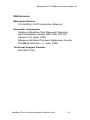
References
Mitsubishi Electric
FR-A500(L) VFD Instruction Manual
Schneider Automation
Modicon Modbus Plus Network Planning
and Installation Guide, 890 USE 100 00
Version 3.0, April 1996
Modicon Modbus Protocol Reference Guide,
PI-MBUS-300 Rev. J, June 1996
Technical Support Number
800-950-7781
Modbus Plus Communications Option Unit
41
Mitsubishi FR-A5NM Instruction Manual
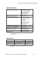
Specifications
Current Consumption
From A500(L) drive:
300 mA typ. @5 Vdc
Provided to Modbus
Plus network:
100 mA @5 Vdc
Backplane Isolation
500 Vdc min.
Supported Data Rates
<= 450 m: 1 Mps,
no repeater;
<= 1800 m: 1 Mps,
repeaters
Maximum distance
between nodes is
450 meters.
Operating Temperature
-10 to 50 oC
Storage Temperature
-20 to 65 oC
(1)
Relative Humidity
<= 90% @50 oC,
non-condensing
Dimensions
96 x 49 x 33 mm
(1)
This refers to a short period of time such as during
transportation.
Revisions
Print Date
Manual Number (1)
Revision
June 1998
VC7BNA00008A
Obsolete version
August 1998
VC7BNA00008 Rev. B
First revision
March 1999
VC7BNA00008 Rev. C
Second revision
(1) The manual number is on the bottom left of the back
cover.
Modbus Plus Communications Option Unit
42
Mitsubishi FR-A5NM Instruction Manual
Index
9
900
900 percent parameter area, 37
900f parameter area, 37
A
A500(L) drive data, 18
accessing
A500(L) drive data, 18
alarm
history, 24
operating when occurs, 24
B
backplane isolation, 42
bit-map
inverter status word, 20
register 40215 input terminal monitor, 22
register 40216 output terminal monitor, 23
C
cables, making, 10
cautions
disposal, 5
injury prevention, 3
input/output terminal assignment, 23
maintenance, inspection, parts replacement, 5
usage, 4
checks
pre-installation, 7
components
prog op dir (d), 39
prog op freq (f), 40
prog op time (t), 38
current consumption, 42
D
diagnostic LED status indicator, 14
dimensions, 42
disposing, 5
drive data
A500(L), 18
Modbus Plus Communications Option Unit
43
Mitsubishi FR-A5NM Instruction Manual
E
error codes, 19
ESD measures, 4
G
grounding
option board, 10
I
installing, 7
connecting to network, 11
pre-installation checks, 7
M
making
cables, 10
manual reset, 17
megaohm meter
testing with, 5
modifying equipment, 4
Modsoft MSTR block, 21
monitor
bit-map for register 40215 input terminal, 22
bit-map for register 40216 outp terminal, 23
real-time, 22
N
network
active node, 14
alarm, 24
communication error, 17
connecting Modbus Plus cable, 11, 13
connecting to, 11
hardware, 10
link, 14
master, 18
operating mode, 15, 16
token, 14
Modbus Plus Communications Option Unit
44
Mitsubishi FR-A5NM Instruction Manual
O
operating
input from Modbus Plus to inverter, 17
modes, 15
selecting the operating mode, 15
when alarm occurs, 24
operating mode
functions available, 17
overview, 15
selecting, 15
operating temperature, 42
option board
grounding, 10
setting Modbus Plus address, 11
output
from inverter, 20
P
parameter
900 percent parameter area, 37
900f parameter area, 37
alarm history, 24
definitions, 19
error codes, 19
normal area, 26
operating when alarm occurs, 24
output from inverter to Modbus Plus, 20
prog op dir (d) components, 39
prog op freq (f) components, 40
prog op time (t) components, 38
real-time monitor, 22
SEV interface, 20
terminal assignment, 23
using the modsoft MSTR block, 21
preventing
injury, 3
prog-op dir components, 39
prog-op freq components, 40
prog-op time components, 38
R
real-time monitor, 22
relative humidity, 42
reset
manual, 17
Modbus Plus Communications Option Unit
45
Mitsubishi FR-A5NM Instruction Manual
S
Schneider Automation, i, 10, 41
setting
switch, 11
switch, alternate method, 13
SEV. See System Environment Variable
specifications
backplane isolation, 42
current consumption, 42
dimensions, 42
operating temperature, 42
relative humidity, 42
storage temperature, 42
supported data rates, 42
status indicator, 14
storage temperature, 42
supported data rates, 42
switch
DIP switch, 14
positions, 11
setting, 11
setting, alternate method, 13
System Environment Variable, 20
T
temperature
operating, 42
storage, 42
terminal assignment, 23
V
voltage, 2, 3, 7
W
warnings
usage, 4
wiring, 2, 10
Modbus Plus Communications Option Unit
46
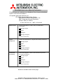
FR-A5NM Instruction Manual Evaluation
Please help us evaluate our Modbus Plus Communications
Option Unit documentation.
Complete and mail this form to:
FR-A500 Option Marketing Group
Mitsubishi Electric Automation, Inc.
500 Corporate Woods Parkway
Vernon Hills, IL 60061
or fax this form to: (847) 478-2253
Ease of use
The documentation is clear, easy to understand,
and helpful.
Strongly agree
Agree
Disagree
Strongly disagree
Specific comments:
Topic
Sequence
Topics are presented in a logical and orderly sequence.
Strongly agree
Agree
Disagree
Strongly disagree
Specific comments:
Technical
Accuracy
Technical diagrams, charts, and instructions provide
accurate information.
Strongly agree
Agree
Disagree
Strongly disagree
Specific comments:
Please fill out both sides of this page.
Modbus Plus Communications Option Unit
Manual No. VC7BNA00008 Revision C March 1999
FR-A5NM Instruction Manual Evaluation
Please help us evaluate our Modbus Plus Communications
Option Unit documentation.
Complete and mail this form to:
FR-A500 Option Marketing Group
Mitsubishi Electric Automation, Inc.
500 Corporate Woods Parkway
Vernon Hills, IL 60061
or fax this form to: (847) 478-2253
Please fill out both sides of this page.
Product
Packaging
Technical diagrams, charts, and instructions provide
accurate information.
Strongly agree
Agree
Disagree
Strongly disagree
Specific comments:
Installation
I was able to install and configure the FR-A5NM using
the documentation.
&
Configuration
Strongly agree
Agree
Disagree
Strongly disagree
Specific comments:
Other
Comments
To Be Completed by Mitsubishi
Received by: _____________ Date:
Reviewed by: _____________ Date:
Corrective Action:
Forward to: ______________ Date:
Modbus Plus Communications Option Unit
Manual No. VC7BNA00008 Revision C March 1999
Please fill out and return the documentation survey.
Modbus Plus Communications Option Unit
Manual No. VC7BNA00008 Revision C March 1999
Mitsubishi FR-A5NM Instruction Manual
This page is intentionally left blank.
Modbus Plus Communications Option Unit
Modbus Plus Communications Option Unit
(FR-A5NM)
This option unit lets you connect a FR-A500(L)
series VFD to a network adhering to the Modbus
Plus communications protocol.
Some important features of this option unit include:
Data rate of 1 Modbus Plus
Support for up to 32 nodes without a repeater
(64 nodes with a repeater) on a single network
Network access to all VFD parameters
Passed Modicon Conformance Test in
March, 1999
Designed and assembled in the U.S.A.
Mitsubishi VFD Instruction Manual
FR-A5NM
© 1999 Mitsubishi Electric Automation, Inc.
Modbus Plus Communications Option Unit
Manual No. VC7BNA00008 Revision C March 1999