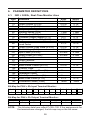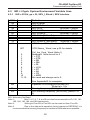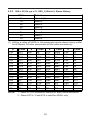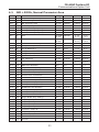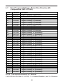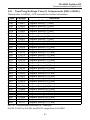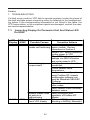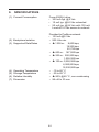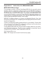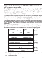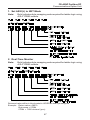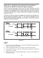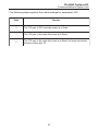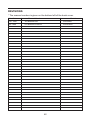
1
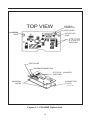
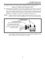
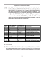
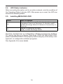
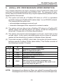
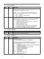
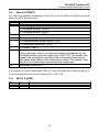
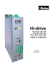
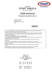
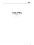
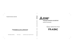
MITSUBISHI ELECTRIC AUTOMATION Instruction Manual FR-A5NP Profibus DP Communications Option Unit Windows, DOS and other product names may be trademarks or registered trademarks of their respective companies. 2 FR-A5NP Profibus DP Communications Option Unit NOTES, CAUTIONS AND WARNINGS NOTE: Notes are used to provide additional detail about a procedure. The Note will always precede the text that the Note refers to. CAUTION: Cautions provide additional detail where failure to observe the Caution may result in damage to the equipment or slight injury to the user. WARNING: Warning provide additional information, where failure to observe the Warning may result in death or severe injury SAFETY INSTRUCTION 1. Electric Shock Prevention WARNING: Do not open or remove the front cover while the Variable Frequency Drive is running. You may get an electrical shock. When necessary to perform inspections or when wiring the unit, switch power off and wait at least 10 minutes and until the bus charge light is off. Check for residual voltage. Do not attempt to inspect or wire this unit unless fully competent to perform the work. Be sure hands are dry before operating any switches. Be sure cables do not have scratches, excessive stress, heavy loads or pinching to prevent electrical shock 2. Injury Prevention CAUTION: Be sure all connections are in accordance with instructions in this manual Check that cables are properly connected before turning equipment on. After turning equipment off, wait at least 10 minutes and until the bus charge light is off before removing cover. With cover removed, charged components may be exposed. 3 3. Additional Cautions and Warnings CAUTION: Do not install the option unit if it is damaged or has parts missing Check that option unit is securely fastened to the variable frequency drive. Do not stand or rest heavy objects on top of unit. Do not allow metal fragments, conductive bodies, oil or other flammable substance to enter the variable frequency drive. Before starting operation, confirm and adjust the parameters. Failure to do so may cause the machines to make unexpected motions. When parameter clear or all parameter clear is performed, each parameter returns to the factory setting. Reset the required parameters before starting operation For prevention of damage caused by static buildup, touch a nearby metal object to remove static from your body. Dispose of this product as general industrial waste. WARNING: Do not modify this equipment 4 FR-A5NP Profibus DP Communications Option Unit TABLE OF CONTENTS Page 1. INTRODUCTION .............................................................................. 7 2. INSTALLATION ................................................................................ 9 2.1. PRE-INSTALLATION CHECKS .................................................. 9 2.2. MOUNTING PROCEDURE ........................................................ 9 2.3. CONNECTING TO THE NETWORK ........................................ 15 2.4. LED STATUS INDICATOR ....................................................... 16 2.5. INSTALLING MEAU0865.GSD ................................................. 16 3. OPERATION ................................................................................... 17 3.1. OPERATING MODES ............................................................. 17 3.2. SELECTING THE OPERATING MODE .................................... 17 3.3. FUNCTIONS AVAILABLE IN THE OPERATING MODES ......... 18 3.4. INPUT FROM PROFIBUS TO VFD .......................................... 18 3.5. OUTPUT FROM VFD TO PROFIBUS ...................................... 19 3.6. OPERATION WHEN AN ALARM OCCURS ............................. 20 4. PROFIBUS DEVICE DATA ............................................................. 21 5. A500(L) VFD PROFIBUS DATA WORD DEFINITION .................... 23 5.1. WORD 1 (PKE) ....................................................................... 25 5.2. WORD 2 (IND) ........................................................................ 26 5.3. WORD 3 ................................................................................. 26 5.4. WORD 4 (PWE2) .................................................................... 26 5.5. WORD 5 (ZSW1) .................................................................... 27 5.6. WORD 6 ................................................................................. 27 6. PARAMETER DEFINITIONS .......................................................... 28 6.1. IND = 0, REAL-TIME MONITOR AREA ................................... 28 6.2. IND = 1, SYSTEM ENVIRONMENT VARIABLE AREA ............ 29 6.2.1. IND = 0100H, SEV_I, SEV INTERFACE ....................... 29 6.2.2. IND = 0101H, SEV_II, ALARM HISTORY ..................... 30 6.3. IND = 2, NORMAL PARAMETER AREA ................................. 31 6.4. IND = 3, 900F PARAMETER AREA ........................................ 38 5 TABLE OF CONTENTS (Continued) Page 6.5. 6.6. 6.7. 6.8. IND = 4, 900% PARAMETER AREA ....................................... 38 IND = 1, SPECIAL AREA ....................................................... 39 IND = 8, TIME/PROG SETTINGS T COMPONENTS ............... 40 IND = 7, TIME/PROG SETTINGS D COMPONENTS ............... 41 7. TROUBLESHOOTING ................................................................... 42 8. REFERENCES .............................................................................. 43 9. SPECIFICATIONS .......................................................................... 44 APPENDIX A. INSTRUCTION FOR MEAU0865.GS ........................... 45 Appendix B. Commonly Used Profibus DP Commands .................... 46 Appendix C. Network Communication Coordination ........................ 58 Appendix D. Other Option Specific Parameters ................................ 60 6 FR-A5NP Profibus DP Communications Option Unit 1. INTRODUCTION GENERAL The purpose of this manual is to provide general information, installation, and operation procedures for the FR-A5NP Profibus DP option, used with the FR-A500(L) Variable Frequency Drive, herein after referred to as the VFD. Read this manual completely before installing, operating or servicing the option unit. This manual is intended for use by qualified personnel. Installation should only be performed by qualified personnel. You must be able to operate and program serial devices to use the equipment. This option unit lets you connect an FR-A500(L) series VFD to a network adhering to the Profibus DP communications protocol. Profibus DP is the performance-optimized version of Profibus for time-critical operations. Illustrations provided in this manual may have covers or safety guards removed to provide a clear view. Before starting operation of the product be sure to install covers and guards into the original position. The following is a list of important features for the option unit Data Rates to 12,000,000 bps. Up to 126 stations supported on a single network Network access to all VFD parameters. Certified by Profibus Nutzer Organization in July 1998 Designed and assembled in the U.S.A.. DESCRIPTION The FR-A5NP option unit consists of two circuit boards as shown in Figure 1-1. The option unit is mounted in option port #3 on the VFD unit. The VFD top cover must be removed to install the option unit. After installation, the top cover is reinstalled and connection to the Profibus DP bus is completed through a connector accessible through the top cover. Two station switches, mounted on the top printed circuit board, allow the assigning of station numbers from 0 to 126. A LED status light mounted next to the connector provides status information on the communication link. 7 TOP VIEW PROFIBUS CONNECTOR STATUS LED MOUNTING HOLE MOUNTING HOLE S TAT I O N NUMBER SWITCHES STATUS LED PROFIBUS CONNECTOR STATION NUMBER SWITCHES MOUNTING HOLES CONNECTOR TO VFD Figure 1-1. FR-A5NP Option Unit 8 FR-A5NP Profibus DP Communications Option Unit 2.0 INSTALLATION Remove the drive cover following the VFD instruction manual and install the option unit using the following procedure: 2.1. Pre-installation Checks (1) Check the VFD type. Use the option unit only with an FR-A500(L) series VFD. Do not use it with any other series (e.g. A200E, A200, A100, Z and F series). These other series VFDs have a different option connector to prevent installation. If you force the connector, you may damage the VFD as well as the option unit. (2) Make sure the VFD input power is off. The option unit can be damaged if installed with the input power on. (3) Make sure the PLC master (or Profibus DP master) is properly grounded before continuing. 2.2. Mounting Procedure WARNING: Hazardous voltage present. Always isolate power from the VFD and wait 10 minutes until the bus charge light is off to ensure the charge lamp has gone out before inserting or removing this option unit or touching the terminals. (1) Insert this option unit only into the OPTION PORT# 3 of the VFD. (2) Carefully insert the connector of the option unit into the connector of the VFD as shown in Figure 2-1. Use the two mounting holes and the guide hole to align the bottom board with the matching machine screw inserts and the plastic guide pin on the VFD. Make sure that the VFD option is firmly seated in the VFD and the connector is fully plugged in. (3) Secure the option unit to the VFD with two mounting screws. If the screw holes in the option unit do not line up with the VFD mounting holes, check that the connectors have been fitted correctly. 9 VSP896M205 3 x 8 mm MACHINE SCREWS WITH FLAT AND LOCK WASHER FR-A5NP PLUG IN OPTION OPTION TO VFD CONNECTOR MITSUBISHI VFD VFD OPTION PORT #3 MACHINE SCREW INSERTS INSTALLED PROFIBUS OPTION IN PORT #3 TERMINAL BLOCK CONNECTOR TO PROFIBUS VFD OPTION PORT #2 VFD OPTION PORT #1 PARAMETER UNIT PORT ALARM LAMP POWER LAMP Figure 2-1. Option Unit Aligned with Option Port #3 10 FR-A5NP Profibus DP Communications Option Unit (4) Option unit is now mechanically installed as shown is Figure 2-2. Figure 2-2. Option Unit Installed In VFD (5) Construct a short cable to connect the network to the VFD. On one end of the cable, install a connector compatible with the network. On the other end, install a DB9-style male connector. Make sure the cable can support 12.0 Mbps communications (as specified in the EEIA-RS-485 standard). This cables connections are shown in Figure 2-3. NOTE: Option unit Pins 6 and 5 supply +5Vdc (rated at 100 mA). Connection of Pins 6 and 5 is optional. Pin 4 may not be required for CONNECTOR SCREWS PROFIBUS CONNECTOR (MALE DB-9 NETWORK DEVICE) PROFIBUS NETWORK CABLE (TO NEXT NETWORK DEVICE) PROFIBUS NETWORK CABLE (FROM NETWORK) your master. Connection of Pin 4 is also optional. Refer to the users manual of your Profibus DP master. 11 Figure 2-3. Connection Cable NOTE: DB-9 Pin 1 2 3 4 5 6 7 8 9 The DB9 pinout described in the table below is defined by the Profibus Standard DIN-19-245 Part 1. The two data signals are named RXD/TXD+ and RXD/TXD-. However, manufacturers of RS485 driver ICs typically refer to these signals as A and B. The Profibus signal RXD/TXD+ is typically assigned to the RS-485 signal A and the RXD/TXD- to B. Some Profibus-DP implementations confuse these two signals. If you are having trouble establishing communications from the FR-A5NP to your Profibus-DP master, verify that the proper data signal assignments are made. It may be necessary to swap these two signal lines. A5NP Internal Signal Name NC NC A RTS Isolated GND Isolated +5Vdc Supply NC B' NC Profibus-DP Signal Name RP RxD/TxD+ CNTR+ DGND (V-) Comments No Connection Reserved for Module Power Receive/Transmit-Data+ Control+ (Request to Send) Data Ground V+ (+5Vdc) Voltage+ RxD/TxDRP No Connection Receive/Transmit-DataReserved for Module Power NC No Connection (6) To terminate the network at the option unit, install termination resistors at the terminal block as shown in Figure 2-5. Each PROFIBUS network has two ends. Units at both of those ends must be properly terminated. 12 FR-A5NP Profibus DP Communications Option Unit CONNECTOR SCREWS PROFIBUS NETWORK CABLE (FROM NETWORK) PROFIBUS CONNECTOR (MALE DB-9 WITH TERMINATION) Figure 2-5. Connector with Termination Resistors CONNECTOR SCREWS PROFIBUS CONNECTOR (MALE DB-9 WITH TERMINATION) PROFIBUS NETWORK CABLE (FROM NETWORK (INPUT)) Figure 2-6. Connectors with Cover Removed 13 220 Ohm 390 Ohm 390 Ohm 1 2 6 3 7 4 8 5 9 N/C N/C RXD/TXD + (POS)* RTS FROM OPTION UNIT DATA GROUND + 5 VOLTS DC N/C RXD/TXD - (NEG)* N/C Ru = 390 Ohm Rt = 220 Ohm Rd = 390 Ohm MALE DB-9 CONNECTOR TERMINATING RESISTORS (All resistors are of 0.25 watts.) Figure 2-7. Termination Resistor Connections 14 FR-A5NP Profibus DP Communications Option Unit NOTE: The option unit may be connected to a DB-9 connector that has these termination resistors built in. (7) Remove the option data port insert from the VFD cover. (8) Set the node address using the two rotary switches on the option unit. The valid addresses can range from 03 through 7B hex (123 decimal). The node address must be set to the value as configured when setting up your Profibus master. The master must be aware of the node addresses assigned to the FR-A5NP or communications will not be established. Refer to user documentation for master details. WARNING: Do NOT set the address from 7C to FF. If you do, the option unit and VFD will not operate correctly. NOTE: Do NOT set more than one station to the same address on a single Profibus DP network. SW1 is nearest to the LED as shown in Figure 1-1 and sets the most significant digit. For example, to set the node address to 7B hex (123 decimal), set SW1 to 7 and SW2 to B. (9) Replace the VFD cover, while making sure that the Profibus connector is aligned with the option data port window. (10) Connect the Profibus cable to the VFD by plugging the DB9-style male connector into DB9-style female connector of the option unit, which should be visible in the option port window. 2.3. Connecting To The Network (1) Make sure the VFD is at rest with power off and the option unit is mounted in the VFD. Connect the Profibus cable created in section 2.2 to the network. (2) It is now safe to apply power to the VFD and run it in PU, external, or net mode, provided that any external VFD control cables in addition to the Profibus network cable are installed correctly. 15 2.4. LED Status Indicator After connecting the option unit to an active network, note the condition of the Operating Status Indicator LED. After power-up or reset, the LED can assume the following states: 2.5. Installing MEAU0865.GSD G reen O ff On State O f System M odule Is Not Pow ered O r M odule Has Not Completed Pow er-up Sequence O r M odule IsNO T In Data Exchange M ode O r Netw ork Connectivity Is Time-out. M odule Is O perating Normally, Ready In Data Exchange M ode. All setup, management, or configuration software programs for ProfibusDP require the use of a Device Data Base (GSD) file MEAU0865.GSD, please install MEAU0865.GSD properly before using any of the setup, management, or configuration software programs. See Appendix A for more details. 16 FR-A5NP Profibus DP Communications Option Unit 3. OPERATION The operation of the A500(L) VFD changes slightly when this option unit is installed. These changes are described in the following paragraphs. 3.1. Operating Modes In the PU operating mode, the VFD is controlled by a Parameter Unit (PU). In the External operating mode, the VFD is controlled by external signals connected to the VFDs terminal block. In the Network (computer link) operating mode, the VFD is controlled by commands from a Profibus master. 3.2. Selecting the Operating Mode The following table describes the actions required to change the operating mode: M ode Change E xt O p e ra tio n ➔ P U O p e ra tion P U O p e ra tion ➔ E xt O p e ra tio n E xt O p e ra tio n ➔ Ne t O p er a tio n Ne t O p er a tio n ➔ E xt O p e ra tio n Ne t O p er a tio n ➔ P U O p e ra tion Ac tio n R e q u ir e d Us e r p re ss e s P U k e y o n P a ra m e ter Unit. Us e r p re ss e s E X T k e y o n P a ra m e ter Unit. P ro fib us m a ste r w rite s 0 0 1 4 h to P NU 0 0 B h (IND = 0 1 0 0 h) . P ro fib us m a ste r w rite s 0 0 1 0 h to P NU 0 0 B h (IND = 0 1 0 0 h) P ro fib us m a ste r w rite s 0 0 11 h to P NU 0 0 B h (IND = 0 1 0 0 h) The following conditions must also be met before you can change the operating mode: the VFD is stopped the forward and reverse commands are off PNU 128h (IND=2) allows you to select the Network operating mode on power-up and after a drive reset. Once the Network operating mode is started, there must be Profibus activity at least once every 5 seconds. If the option unit does not sense valid Profibus activity for 5 seconds or more, it performs an option module alarm stop, the VFD display unit shows E.OP3, and you must reset the VFD to clear this fault. 17 One way to ensure activity is to configure the Profibus master to enable response monitoring. Alternatively, you can have the Profibus master issue a null command (Command Word 1 = 0) or any other command. Refer to Section 5. 3.3. Functions Available in the Operating Modes The functions available to the drive depend on the operating mode. The following table indicates the command types available according to the operating mode: Control Type Command Type Profibus Operating Command Output Freq. Set. Monitor Parameter Write Parameter Read VFD Reset External Operating Command Terminals Output Freq. Set. VFD Reset (1) (2) (3) (*) Net Yes(1) Yes(1) Yes Yes(3)(*) Yes Yes(2) Yes(1) Yes(1) Yes Ext No No Yes No(3) Yes No Yes Yes Yes PU No No Yes No(3) Yes No No No Yes Depends on value of PNU 126h and 127h. VFD cant be reset if a Profibus comm. error occurred. As set in PNU 4Dh. While stopped. 3.4. Input From Profibus to VFD This option unit supports all Control Input Commands. The output frequency setting may range from 0 to 400 Hz in increments of 0.01 Hz. You can reset the VFD by having the Profibus master write a 0000h to PNU 001h (IND=0100h). For parameter writing, all standard and special parameters are supported. 18 FR-A5NP Profibus DP Communications Option Unit 3.5. Output From VFD to Profibus You can monitor the following items: Output Frequency Output Current Output Voltage Frequency Setting Running Speed (RPM) Motor Torque Converter Output Voltage Regenerative Brake Duty Electronic Overcurrent Protection Load Factor Output current peak value Peak Voltage Input Power Output Power Input Terminal Output Terminal Refer to Section 6.1 for more details. For parameter reading, all standard and special parameters are supported. All available parameters are readable all the time, regardless of special settings that may be needed to read parameters using the PU or other communications option cards (e.g., PNU 3Dh~40h and C9~E6). 19 3.6. Operation When an Alarm Occurs. The following table shows the behavior of the VFD and network when an alarm occurs: Fault Type Item VFD *2 VFD Operation Network Comm. Profibus VFD Operation Comm. Network Comm. Net Stop Continue Stop Continue *1 Ext Stop Continue Continue Continue *1 PU Stop Continue Continue Continue *1 *1: Depends on the type of communication fault. *2: For examples, E.OP3, E.OC1. CAUTION: Profibus-DP communication routines should check the acknowledge bits ( PKE-AK) returned by slave device to verify successful transmission of the command and acceptance by slave device. See Appendix C for details. CAUTION: For your safety, the output frequency of the VFD should always be monitored via Profibus. The actual frequency of the VFD should match the frequency setting issued by the master. If the output frequency of the VFD is less than the frequency (RFR) set by the master, a STOP command has been issued. 20 FR-A5NP Profibus DP Communications Option Unit 4. PROFIBUS DEVICE DATA The network masters configuration software uses a device data file to identify features and functionality of a Profibus DP device. The file (named MEAU0865.GSD) is an ASCII file that can be obtained from Mitsubishi or typed in directly by the user with the following data. Comments are not included in the ASCII file itself. Parameter #Profibus_DP Vendor_Name Model_Name Ident_Number Revision Protocol_Ident Station_Type FMS_Supp Hardware_Release Software Release 9.6_supp 19.2_supp 93.75_supp 187.5_supp 500_supp 1.5M_supp 3M_supp 6M_supp 12M_supp MaxTsdr_9.6 MaxTsdr_19.2 MaxTsdr_93.75 MaxTsdr_187.5 MaxTsdr_500 MaxTsdr_1.5M MaxTsdr_3M MaxTsdr_6M MaxTsdr_12M Redundancy Repeater_Ctrl_Sig Value Comments File Header = Mitsubishi Electric Automation, Inc. = FR-A5NP = 0x0865 = Revision #.## = 0 = 0 = 0 = Series ** = Revision #.## = 1 = 1 = 1 = 1 = 1 = 1 = 1 = 1 = 1 = 60 = 60 = 60 = 60 = 100 = 150 = 250 = 450 = 800 = 0 = 2 (3) A500(L) VFD Option = 2149 Decimal See HW & SW Release Profibus DP 9600 bps supported 19.2K bps supported 93.75K bps supported 187.5K bps supported 500K bps supported 1.5M bps supported 3M bps supported 6M bps supported 12M bps supported 60 bit times 60 bit times 60 bit times 60 bit times 100 bit times 150 bit times 250 bit times 450 bit times 800 bit times No redundancy Ctrl-P is TTL-Level 24V_Pins = 0 Net 24VDC not connected Freeze_Mode_supp = 1 Freeze supported Sync_Mode_supp = 1 Sync mode supported 21 Parameter Auto_Baud_supp Value = 1 Comments Auto Baud Detect supported Set_Slave_Add_supp = 0 Set Slave Address not supported User_Prm_Data_Len = 0 No user parameter data Min_Slave_Interval = 1 Modular_Station = 0 No Modular unit(1) Max_Module = 1 1 ID Byte Max_Input_Len = 12 12 Input bytes Max_Output_Len = 12 12 Output bytes Max_Data_Len = 24 12+12 = 24 Module = 6 Word Input/6 Word Output 0x75 Code=117=0x75 for 6w I/Os (2) EndModule NOTES: Some master PLCs require that Modular_Station=1 &/ Min_Slave_Intervall=20. (1) 0x75 = 117: code automatically generated for I/Os = 6W by COM ET 200. (2) Some master devices require that vendor_name is at most 10 characters long, please use Mitsubishi in that case. (3) To view this file on disk, please use a text editor. 22 FR-A5NP Profibus DP Communications Option Unit 5. A500(L) VFD PROFIBUS DATA WORD DEFINITION This chapter describes the basic structure of the Profibus DP data word and how it is implemented within the A500(L) VFD. For examples of commonly used commands and how they may be implemented, please refer to Appendix B in this manual. (1) This option unit acts as a Profibus DP slave to a PLC or equivalent controller acting as a Profibus DP master class 1 on an RS-485 network. This means that the option unit: acknowledges messages received, and transmits messages at the request of a network master. (2) The option unit can also act as a Profibus DP slave to a Profibus DP master, which can read the drives I/O values, as well as configure the drive itself. Please refer to Profibus Specifications. (3) The option unit cannot send messages on its own, and it has no bus access rights. It also cannot simultaneously act as a slave to network master and as a lead drive (master) to follower drives (slaves). (4) To provide access to A500(L) drive data, this option unit uses a manufacturer-specific Profibus Profile (data buffer). This Profile consists of the following 6 words (12 bytes): Word Id 1 PKE 2 3 4 IND PWE1 PWE2 5 ZSW1 6 HIW NOTE: Definition Parameter Number (PNU) and Task or response Id (AK) Parameter Index (category) Not used and must be set to 0 Parameter Value VFD Status word. Used for slave-to-master messages only. For master-to-slave messages, this word is not used and must be set to 0. Not used and must be set to 0 Messages from Master to Slave are called Command Requests. Messages from Slave to Master are called Command Responses. 23 (5) Some Master devices, such as the Mitsubishi A1SJ71PB92D Programmable Controller will require that this data be sent to the VFD in a byteswapped configuration. In this case, the position of the high-order byte and the low-order byte are switched in the data string. The FR-A5NP communications buffer memory map is illustrated in the following tables: Bit No: Bit No: Bit No: Bit No: Parameter Id 15 AK 12 Parameter Index 15 Index 11 SPM 8 0 PNU (IND) 7 Word #2 0 Value Parameter Value 15 Parameter Value HIGH Parameter Value LOW Process Data 15 Command Count Reserved Word #1 (PKE) 10 8 (PWE) 0 (PWE1) (PWE2) 7 Status (HIW) Word #3 Word #4 0 (ZSW1) Word #5 Word #6 AK: Task or Response Id SPM: Toggle bit for processing the parameter change report. (Not supported, should always be zero.) PNU: Parameter number (6) These 6 words (described in following subsections) are how the network master and slave (the option unit) communicate via the Profibus DP protocol. It is through this addressing scheme that the sender indicates which data word within the drive is being accessed and what that access is. 24 FR-A5NP Profibus DP Communications Option Unit (7) This option unit does not support any other manufacturer-specific messages/parameters. 5.1. Word 1 (PKE) Bits Id Definition 0-10 PNU 11 12-15 AK Parameter Number (PNU). Together, the PNU and the IND (word 2 of the Profibus Profile) define which data word is being accessed. Section 6 of this manual lists all of the parameters that you can access. Not used and must be set to 0. Task or response Id value. For task telegrams from the network master to the slave, i.e. Cmd_Req, the AK can assume the following values: 0h = no task 1h = request parameter value, read 2h = change parameter value (word), write 3h~Fh = not supported For task telegrams from the slave to the network master, i.e. Cmd_Rsp, the AK can assume the following values: 0h = VFD busy. No data returned by VFD 1h = VFD ready to accept data transmission 2h~6h = not supported 7h = task cannot be executed (error number placed in PWE, word 4 of the Profibus Profile) 8h = no operation change rights 9h~Fh = not supported NOTE: See appendix C for more information regarding communication coordination. 25 5.2. Bits 0-7 8-15 5.3. Bits 0-15 Word 2 (IND) Id pp IND Definition Page Index. Some special parameters require a page Index. If it is not needed it should be set to 0. If IND = 01, for system environment variables, the follow ing cases specify different blocks of SEV's: 0 = sev_i, block I 1 = sev_ii, block ii, alarm history 2 = sev_iii, block iii Parameter Index. Specifies the area from which the Specific Parameter Number (PNU) is being accessed (see Section 6): 0h = real-time monitor area 1h = system environment variable area (3 blocks) 2h = normal parameter area 3h = 900f parameter area 4h = 900% parameter area 6h = Time/Prog Settings (frequency component) 7h = Time/Prog Settings (direction component) 8h = Time/Prog Settings (time component) Word 3 (PWE1) Id PWE1 Definition Reserved and should be set to 0 5.4. Word 4 (PWE2) Bits 0-15 Id PWE2 Definition Parameter Value. The actual data transferred in a telegram. If a task could not be executed (AK response Id = 7), the PWE indicates the type of error detected: 0h = no error 1h = unsupported task (including busy writing state) 2h = invalid Index (IND) 3h = invalid Parameter Number (PNU) 4h = dual-port read failure 5h = dual-port write failure 6h = invalid page 41h = mode error 42h = instruction code error 43h = data range error 26 FR-A5NP Profibus DP Communications Option Unit 5.5. Word 5 (ZSW1) For slave-to-master messages. Word 5 of the Profibus Profile is used to pass the VFD status word: Bits 0 1 2 3 4 5 6 7 8-14 15 Definition 1 = running (RUN) 1 = forward running (FWD) 1 = reverse running (REV) 1 = up to frequency (SU) 1 = overload (OL) 1 = instantaneous power failure (IPF) 1 = frequency detection (FU) 1 = alarm (ABC) Command count. The command count is an optional feature maintained by the Profibus master and can range from 00H-7FH. The option unit copies the command count from the command it receives to the same byte offset in the response it sends. The master may use this to synchronize commands and responses. Reserved, must be 0. For master-to-slave messages, Bits 0-7 are not used and must be set to 0. The bit-wise data here do not reflect Pr.s 190~195. 5.6. Bits 0-15 Word 6 (HIW) Id HIW Definition Reserved and should be set to 0 27 6. PARAMETER DEFINITIONS 6.1. IND = 0000h, Real-Time Monitor Area PNU 0h 1h 2h 4h 5h 6h 7h 8h 9h Ah Bh Ch Dh Eh Fh 10h 11h 12h 13h 15h 16h 17h 18h Definition Output Current (0.01A) Output Voltage (0.1V) Frequency Setting (0.01Hz) Running Speed (1r/m) Motor Torque (0.1%) Converter Output Voltage (0.1V) Regenerative Brake Duty (0.1%) Electronic Overcurrent Protection Load Factor Output Current Peak Value (0.01A) Peak Voltage (0.1V) Input Power (0.01kW) Output Power (0.01kW) Input Terminal Output Terminal Load Meter Motor Excite Current (0.01A) Position Pulse Cumulative Energy Time (1h) Orientation Status Actual Operation Time (1h) Motor Load Factor (0.1%) Cumulative Power (1kWh) A500 0.01Hz 0.01A 0.1V 0.01Hz 1 rpm 0.01% 0.1V 0.1% A500L 0.01Hz 0.1A 0.1V 0.01Hz 1 rpm 0.01% 0.1V 0.1% 0.1% 0.1% 0.01A 0.1V 0.01kW 0.01kW 0.1A 0.1V 0.1kW 0.1kW 0.01A 0.1A 1 hour 1 hour 1 hour 0.1% 1kWh 1 hour 0.1% 1kWh Bit-Map for PNU = Eh Input Terminal Monitor: 15..12 11 0 CS 10 9 8 RES STOP MRS 7 6 5 4 3 2 1 0 JOG RH RM RL RT AU STR STF Bit-Map for PNU = Fh Output Terminal Monitor: 15. .6 5 4 3 2 1 0 0 Relay FU OL IPF SU RUN NOTE: The bit-wise data here reflect Pr190~195. If the assignments for the terminals are changed, the bit-map may not be the same. 28 FR-A5NP Profibus DP Communications Option Unit 6.2 IND = 01pph, System Environment Variable Area 6.2.1 IND = 0100h, pp = 00, SEV_I, Block I, SEV Interface PNU 0h 1h 2h 3h 4h 5h 6h 7h Ah Bh Dh Eh Definition UsrClrValSet WO:VFD Reset WO:PrClr, WO:PrAllClr, WO:PrUsrClr, WO:PrClr (ExComPr), WO:PrAllClr (ExComPr), WO:PrUsrClr (ExComPr), VFD Status/CtrlInpCmd, WriteVal = 965Ah WriteVal = 99AAh WriteVal = 5A55h WrtieVal = 5A96h WriteVal = AA99h WriteVal = 555Ah WriteVal = XXh BIT VFD Status_ Word, see p.20 for details 0 1 2 3 4 5 6 7 8 9 10 11-15 Ctrl_Inp_Cmd_ Word (Note 1) Reserved. Must be set to 0 1 = STF 1 = STR 1 = RH 1 = RM 1 = RL 1 = JOG 1 = RT 1 = AU 1 = CS 1 = MRS Not used and always set to 0 See Appendix B for examples. OpMode/VFDConfig(Ext10h/Net14h), WriteVal = 1Xh Running frequency (RAM) (Note 2) WO:Running frequency (EEPROM) (Notes 2 & 3) WO: Write only, No Read. Note 1: Bits 3, 4, 5, 6, 7, 8, and 9 can also be accessed from Pr 182, 181, 180, 185, 183, 184, and 186 respectively. Note 2: Writing to Pnu=Dh or Pnu=Eh can be read out from Pnu=Dh. Note 3: Due to the data write operation limits inherent to EEPROM, it is recommended that running frequency be written to RAM whenever possible. 29 6.2.2 IND = 0101h, pp = 01, SEV_II, Block II, Alarm History PNU 0h 1h 2h 3h 4h 5h 6h 7h Definition Alarm 1 (1) Alarm 2 Alarm 3 Alarm 4 Alarm 5 Alarm 6 Alarm 7 Alarm 8 (1) Writing a value of 0000h to this parameter resets alarm history buffer for all alarms. All other parameters at this index are read only. # 10h 11h 12h 20h 21h 22h 30h 31h 40h 41h 50h 51h 60h 70h NOTE: Code OC1 OC2 OC3 OV1 OV2 OV3 THT THM FIN FAN IPF UVT OLT BE # 80h 81h 90h A0h A1h A2h A3h B0h B1h B2h C0h C1h C2h D0h Code GF LF OHT OPT OP1 OP2 OP3 PE PUE RET CPU CTE P24 OS # D1h D2h D3h D4h D5h D6h D7h D8h D9h DAh DBh F0h F1h F2h Code OSd ECT Od ECA Mb1 Mb2 Mb3 Mb4 Mb5 Mb6 Mb7 E0 E1 E2 # F3h F4h F5h F6h F7h F8h F9h FAh FBh FCh FDh FEh FFh Code E3 E4 E5 E6 E7 E8 E9 E10 E11 E12 E13 E14 E15 1. Refer to VFD Instruction Manual for alarm code definitions 2. Alarm # FFh / Code E15 is valid for A500L only 30 FR-A5NP Profibus DP Communications Option Unit 6.3. IND = 0200h, Normal Parameter Area Para PNU Definition Range Hex A500 Pr0 0h Torque Boost (Manual) 0-30 0-12C 0.1% 0.1% Pr1 1h Max frequency Limit 0-120 0-2EE0 0.01Hz 0.01Hz Pr2 2h Min frequency Limit 0-120 0-2EE0 0.01Hz 0.01Hz Pr3 3h Base frequency Limit 0-400 0-9C40 0.01Hz 0.01Hz Pr4 4h MultiSpeed Set (HiSpeed) 0-400 0-9C40 0.01Hz 0.01Hz Pr5 5h MultiSpeed Set (MiSpeed) 0-400 0-9C40 0.01Hz 0.01Hz Pr6 6h MultiSpeed Set (LoSpeed) 0-400 0-9C40 0.01Hz 0.01Hz Pr7 7h Acc t 0-3600/ 0-8CA0 0-360 0.1s/ 0.01s 0.1s/ 0.01s Pr8 8h Dec t 0-3600/ 0-8CA0 0-360 0.1s/ 0.01s 0.1s/ 0.01s Pr9 9h Electr Therml O/L Relay 0-500 0-C350 0.01A 0.1A Pr10 Ah DC Inj Brake Op f 0-120 0-2EE0 0.01Hz 0.01Hz Pr11 Bh DC Inj Brake Op t 0-10 0-64 0.1s 0.1s Pr12 Ch DC Inj Brake V 0-30 0-12C 0.1% 0.1% Pr13 Dh Startg frequency 0-60 0-1770 0.01Hz 0.01Hz Pr14 Eh Applied Load Pattern 0-5 0-5 Pr15 Fh Jog frequency 0-400 Pr16 10h Jog Acc/Dec t Pr17 11h MRS Input Selection 0-2 Pr18 12h HiSpeed Max frequency Limit 120-400 2EE0-9C40 0.01Hz Pr19 13h Base frequency V 0-1000 0-2710 Pr20 14h Acc/Dec Ref frequency 0-400 Pr21 15h Acc/Dec time Increments 0-1 0-1 Pr22 16h Pr22 Stall Prevention Op Level 0-200 0-7D0 Pr23 17h Stall Prevention Op Level At DoubleSpeed 0-200 0-7D0 0.1% 0.1% Pr24 18h MultiSpeed Set (Speed4) 0-400 0-9C40 0.01Hz 0.01Hz Pr25 19h MultiSpeed Set (Speed5) 0-400 0-9C40 0.01Hz 0.01Hz Pr26 1Ah MultiSpeed Set (Speed6) 0-400 0-9C40 0.01Hz 0.01Hz Pr27 1Bh MultiSpeed Set (Speed7) 0-400 0-9C40 0.01Hz 0.01Hz Pr28 1Ch MultiSpeed Input Compensation 0-1 0-1 1 1 Pr29 1Dh Acc/Dec Pattern 0-3 0-3 1 1 Pr30 1Eh Regen Brake Duty Change 0-2 0-2 1 1 Pr31 1Fh Frequency Jump 1A 0-400 0-9C40 0.01Hz 0.01Hz Pr32 20h Frequency Jump 1B 0-400 0-9C40 0.01Hz 0.01Hz Pr33 21h Frequency Jump 2A 0-400 0-9C40 0.01Hz 0.01Hz Pr34 22h Frequency Jump 2B 0-400 0-9C40 0.01Hz 0.01Hz Pr35 23h Frequency Jump 3A 0-400 0-9C40 0.01Hz 0.01Hz Pr36 24h Frequency Jump 3B 0-400 0-9C40 0.01Hz 0.01Hz Pr37 25h Speed Display 0-9998 0-270E 1 1 Pr38 26h Special Pr39 27h Special 31 A500L 1 1 0-9C40 0.01Hz 0.01Hz 0-3600/ 0-8CA0 0-360 0.1s/ 0.01s 0.1s/ 0.01s 0-2 0-9C40 1 1 0.01Hz 0.1V 0.1V 0.01Hz 0.01Hz 1 1 0.1% 0.1% Para Pr40 PNU 28h Definition Special Range Hex Pr41 29h Up-To- Frequency Sensitivity 0-100 0-3E8 0.1% 0.1% Pr42 2Ah Output Frequency Detection 0-400 0-9C40 0.01Hz 0.01Hz Pr43 2Bh Output Frequency Detection At REV rotation 0-400 0-9C40 0.01Hz 0.01Hz Pr44 2Ch 2nd Acc/Dec time 0-3600/ 0-8CA0 0-360 0.1s/ 0.01s 0.1s/ 0.01s Pr45 2Dh 2nd Dec time 0-3600/ 0-8CA0 0-360 0.1s/ 0.01s 0.1s/ 0.01s Pr46 2Eh 2nd Torque Boost 0-30 0-12C Pr47 2Fh 2nd V/F (Base frequency) 0-400 0-9C40 Pr48 30h 2nd Stall Prevention Op I 0-200 0-7D0 0.1% 0.1% Pr49 31h 2nd Stall Prevention Op frequency 0-400 0-9C40 0.01Hz 0.01Hz Pr50 32h 2nd Outp frequency Detection 0-400 0-9C40 0.01Hz 0.01Hz Pr51 33h Special Pr52 34h PU Main Display Data Selection 0-100 0-64 1 1 Pr53 35h PU Level Display Data Selection 0-18 0-12 1 1 Pr54 36h FM Termnl Func Selection 1-21 1-15 1 1 Pr55 37h frequency Monitoring Ref 0-400 0-9C40 0.01Hz 0.01Hz Pr56 38h Current Monitorg Ref 0-500 0-C350 0.01A 0.1A Pr57 39h Restart Coasting Time 0-5 0-32 0.1s 0.1s Pr58 3Ah Restart Cushion Time 0-60 0-258 0.1s 0.1s Pr59 3Bh Remote Setting Function Selection 0-2 0-2 1 1 Pr60 3Ch Intellgent Mode Selection 0-8 0-8 1 1 Pr61 3Dh Ref Current For Intellgent Mode 0-500 0-C350 0.01A O.1A Pr62 3Eh Ref Current For Intellgent Mode Acc 0-200 0-7D0 0.1% 0.1% Pr63 3Fh Ref Current For Intellgent Mode Dec 0-200 0-7D0 0.1% 0.1% Pr64 40h Starting frequency For Elevator Mode 0-10 0-3E8 0.01Hz 0.01Hz Pr65 41h Retry Selection 0-5 0-5 1 1 Pr66 42h Stall Prevention Op Reduction Starting frequency 0-400 0-9C40 0.01Hz 0.01Hz Pr67 43h No. Of Retries At Alarm Occur 0-110 0-6E 1 1 Pr68 44h Retry Waiting Time 0-10 0-64 0.1s 0.1s Pr69 45h Retry Count Display Erasure 0 0 Pr70 46h Special Regen Brake Duty 0-30 0-12C Pr71 47h Applied Motor 0-24 0-18 1 1 Pr72 48h PWM Frequency Selection 0-15 0-F 1 1 Pr73 49h 0 to 5V, 0 to 10V Selection 0-15 0-F 1 1 Pr74 4Ah Response Time For Analog Signal 0-8 0-8 1 1 Pr75 4Bh Reset/Disconnectd PU Detection/ PU Stop Selection 0-17 0-11 1 1 Pr76 4Ch Alarm Code Output Selection 0-3 0-3 1 1 Pr77 4Dh Pr Write Disable Selection 0-2 0-2 1 1 Pr78 4Eh REV Rotation Prevention Selection 0-2 0-2 1 1 Pr79 4Fh Operating Mode Selection 0-8 0-8 1 1 32 A500 A500L 0.1% 0.1% 0.01Hz 0.01Hz 1 1 0.1% 0.1% FR-A5NP Profibus DP Communications Option Unit Para PNU Definition Range Hex Pr80 50h Motor Capacity .4-55 28-157C A500 A500L 0.01kW 0.1kW Pr81 51h No. Of Motor Poles 2-16 2-10 1 1 Pr82 52h Excitation Current 0-9999 0-270F 0.01A 0.01A Pr83 53h Rated Motor Voltage 0-1000 0-2710 0.1V Pr84 54h Rated Motor Frequency 50-120 1388-2EE0 0.01Hz Pr85 55h Special Pr86 56h Special Pr87 57h Special Pr88 58h Special Pr89 59h Speed Control Gain 0-1000 0-2710 0.1% 0.1% Pr90 5Ah Motor Constant R1 0-9999 0-270F 0.01 0.01 Pr91 5Bh Motor Constant R2 0-9999 0-270F 0.01 0.01 Pr92 5Ch Motor Constant L1 0-9999 0-270F 0.01 0.01 Pr93 5Dh Motor Constant L2 0-9999 0-270F 0.01 0.01 Pr94 5Eh Motor Constant X 0-9999 0-270F 0.01 0.01 Pr95 5Fh Online Auto Tuning 0-1 0-1 1 1 Pr96 60h Autotuning Set/State 0-101 0-65 1 1 Pr97 61h Special Pr98 62h Special Pr99 63h 0-9C40 0.01Hz 0.01Hz 0.1V 0.01Hz Special Pr100 64h V/F 1 (1st Frequency) 0-400 Pr101 65h V/F 1 (1st Frequency Voltage) 0-1000 0-2710 Pr102 66h V/F 2 (2nd Frequency) 0-400 Pr103 67h V/F 2 (2nd Frequency Voltage) 0-1000 0-2710 Pr104 68h V/F 3 (3rd Frequency) 0-400 Pr105 69h V/F 3 (3rd Frequency Voltage) 0-1000 0-2710 Pr106 6Ah V/F 4 (4th Frequency) 0-400 Pr107 6Bh V/F 4 (4th Frequency Voltage) 0-1000 0-2710 Pr108 6Ch V/F 5 (5th Frequency) 0-400 0-9C40 0-9C40 0-9C40 0-9C40 0.1V 0.1V 0.01Hz 0.01Hz 0.1V 0.1V 0.01Hz 0.01Hz 0.1V 0.1V 0.01Hz 0.01Hz 0.1V 0.1V 0.01Hz 0.01Hz Pr109 6Dh V/F 5 (5th Frequency Voltage) 0-1000 0-2710 0.1V 0.1V Pr110 6Eh 3rd Acc/Dec Time 0-3600/ 0-8CA0 0-360 0.1s/ 0.01s 0.1s/ 0.01s Pr111 6Fh 3rd Dec Time 0-3600/ 0-8CA0 0-360 0.1s/ 0.01s 0.1s/ 0.01s Pr112 70h 3rd Torque Boost 0-30 0-12C Pr113 71h 3rd V/F (Base Frequency) 0-400 0-9C40 Pr114 72h 3rd Stall Prevention Op Current 0-200 0-7D0 0.1% 0.1% Pr115 73h 3rd Stall Preventn Op Frequency 0-400 0-9C40 0.01Hz 0.01Hz Pr116 74h 3rd Outp Frequency Detection 0-400 0-9C40 0.01Hz 0.01Hz Pr117 75h Station No. 0-31 0-1F 1 1 Pr118 76h Comms Speed 48-192 30-C0 1 1 Pr119 77h Stop Bit Length 0-11 0-B 1 1 Pr120 78h Parity Check Presence / Absence 0-2 0-2 1 1 Pr121 79h No. Of Comms Retries 0-10 0-A 1 1 33 0.1% 0.1% 0.01Hz 0.01Hz Para PNU Pr122 7Ah Definition Comms Chk Time Interval Range Hex 0-999.8 0-270E A500 0.1s A500L 0.1s Pr123 7Bh Pr124 7Ch Waiting Time Setting 0-150 0-96 1ms 10ms CR,LF Presence/Absence Selection 0-2 0-2 1 Pr125 7Dh Special 1 Pr126 7Eh Special A-15 Pr127 7Fh Special Pr128 80h PID Actn Selection 10-21 Pr129 81h PID Proportionl Band 0.1-10000.1-2710 Pr130 82h PID Integral Time 0.1-36001-8CA0 0.1s 0.1s Pr131 83h PID Upper Limit 0-100 0-3E8 0.1% 0.1% Pr132 84h PID Lower Limit 0-100 0-3E8 0.1% 0.1% Pr133 85h PID Actn Set Point For PU Op 0-100 0-3E8 0.1% 0.1% Pr134 86h PID Differentl Time 0.01-10 1-3E8 0.01s 0.01s Pr135 87h CPS-INV Switch-Over Sequence Output terminal Selection 0-2 0-2 1 1 Pr136 88h MC Switch-Over Interlock Time 0-100 0-3E8 0.1s 0.1s Pr137 89h Starting Waiting Time 0-100 0-3E8 0.1s 0.1s Pr138 8Ah CPS-INV Switch-Over Selection at Alarm Occcur 0-1 0-1 1 1 Pr139 8Bh Auto INV-CPS Switch-Over Frequency 0-60 0-1770 0.01Hz 0.01Hz Pr140 8Ch Backlash Acc Stopping Frequency Frequency 0-400 0-9C40 0.01Hz 0.01Hz Pr141 8Dh Backlash Acc Stopping Time 0-360 0-E10 Pr142 8Eh Backlash Dec Stopping Frequency 0-400 0-9C40 Pr143 8Fh Backlash Dec Stopping Time 0-360 Pr144 90h Speed Setting Switch-Over 0-110 Pr145 91h PU Language Switch Pr146 92h Special Pr147 93h Special Pr148 94h Pr149 95h 1 1 0.1% 0.1% 0.1s 0.1s 0.01Hz 0.01Hz 0-E10 0.1s 0.1s 0-6E 1 1 0-7 0-7 1 1 Stall Prevention Level At 0V Input 0-200 0-7D0 0.1% 0.1% Stall Prevention Level At 10V Input 0-200 0-7D0 0.1% 0.1% Pr150 96h Output Current Detection Level 0-200 0-7D0 0.1% 0.1% Pr151 97h Output Current Detection Period 0-10 0-64 0.1s 0.1% Pr152 98h 0-I Detection Level 0-200 0-7D0 0.1% 0.1% Pr153 99h 0-I Detection Period 0-1 0-64 0.01s 0.01s Pr154 9Ah Voltage Reduction Selection During Stall Prevention Op 0-1 0-1 1 1 Pr155 9Bh RT Activatd Condition 0-10 0-A 1 1 Pr156 9Ch Stall Prevention Op Selection 0-100 0-64 1 1 Pr157 9Dh OL Signal Waiting Timet 0-25 0-FA 0.1s 0.1s Pr158 9Eh AM Terminal Funtion Selection 1-21 1-15 1 1 Pr159 9Fh Special 0-11 0-B 1 1 0-1 0-1 1 1 Pr160 A0h Usr Group Read Selection Pr161 A1h Special Pr162 A2h Auto Restart After IPF Selection 34 FR-A5NP Profibus DP Communications Option Unit Para PNU Pr163 A3h Definition 1st Cushion Time For Restart Range 0-20 Hex 0-C8 A500 0.1s A500L 0.1s Pr164 A4h 1st Cushion Voltage For Restart 0-100 0-3E8 0.1s 0.1s Pr165 A5h Restart Stall Prevention Op Level 0-200 0-7D0 0.1s 0.1s Pr166 A6h Special Pr167 A7h Special Pr168 A8h Special Pr169 A9h Special Pr170 AAh Watt-Hr Meter Clear 0 0 1 1 Pr171 ABh Actl Op Hr Meter Clear 0 0 1 1 Pr172 ACh Special Pr173 ADh Usr Group 1 0-999 0-3E7 1 1 Pr174 AEh Usr Group 1 Deletn 0-999 0-3E7 1 1 Pr175 AFh Usr Group 2 0-999 0-3E7 1 1 Pr176 B0h Usr Group 2 Deletn 0-999 0-3E7 1 1 Pr177 B1h Special Pr178 B2h Special Pr179 B3h Special 1 Pr180 B4h RL Termnl Funct Select 0-99 0-63 1 Pr181 B5h RM Termnl Func Selectn 0-99 0-63 1 1 Pr182 B6h RH Termnl Func Select 0-99 0-63 1 1 Pr183 B7h RT Termnl Func Select 0-99 0-63 1 1 Pr184 B8h AU Termnl Func Select 0-99 0-63 1 1 Pr185 B9h JOG Termnl Func Select 0-99 0-63 1 1 Pr186 BAh CS Termnl Func Select 0-99 0-63 1 1 Pr187 BBh Special Pr188 BCh Special Pr189 BDh Special Pr190 BEh RUN Termnl Func Select 0-199 0-C7 1 1 Pr191 BFh SU Termnl Func Select 0-199 0-C7 1 1 Pr192 C0h IPF Termnl Func Select 0-199 0-C7 1 1 Pr193 C1h OL Termnl Func Select 0-199 0-C7 1 1 Pr194 C2h FU Termnl Func Select 0-199 0-C7 1 1 Pr195 C3h ABC Termnl Func Select 0-199 0-C7 1 1 Pr196 C4h Special Pr197 C5h Special Pr198 C6h Special Pr199 C7h Usrs Initl Val Sett 0-999 0-3E7 1 1 Pr232 E8h MultiSpd Sett (Spd8) 0-400 0-9C40 0.01Hz 0.01Hz Pr233 E9h MultiSpd Sett (Spd9) 0-400 0-9C40 0.01Hz 0.01Hz Pr234 EAh MultiSpd Sett (Spd10) 0-400 0-9C40 0.01Hz 0.01Hz Pr235 EBh MultiSpd Sett (Spd11) 0-400 0-9C40 0.01Hz 0.01Hz Pr236 ECh MultiSpd Sett (Spd12) 0-400 0-9C40 0.01Hz 0.01Hz Pr237 EDh MultiSpd Sett (Spd13) 0-400 0-9C40 0.01Hz 0.01Hz Pr238 EEh MultiSpd Sett (Spd14) 0-400 0-9C40 0.01Hz 0.01Hz 35 Para Definition Range Hex Pr239 EFh PNU MultiSpd Sett (Spd15) 0-400 0-9C40 Pr240 F0h Special Pr241 F1h Special Pr242 F2h Special Pr243 F3h Special Pr244 F4h Special Pr245 F5h Special Pr246 F6h Special Pr247 F7h Special Pr248 F8h Special Pr249 F9h Special Pr250 FAh Special Pr251 FBh Special Pr252 FCh Special A500 A500L 0.01Hz 0.01Hz Pr253 FDh Special Pr254 FEh Special Pr255 FFh Special Pr256 100h Special Pr257 101h Special Pr258 102h Special Pr259 103h Special Pr260 104h Special Pr261 105h Power Failure Stop Func 0-1 0-1 1 1 Pr262 106h Subtracted Frequency At Dec Start 0-20 0-7D0 0.01Hz 0.01Hz Pr263 107h Subtractn Starting Frequency 0-120 0-2EE0 0.01Hz 0.01Hz Pr264 108h Power-Failure Dec Time 1 0-3600/ 0-8CA0 0-360 0.1s/ 0.01s 0.1s/ 0.01s Pr265 109h Power Failure Dec Time 2 0-3600/ 0-8CA0 0-360 0.1s/ 0.01s 0.1s/ 0.01s Pr266 10Ah Power Failure Dec Time Swc-Over f 0-400 0-9C40 0.01Hz 0.01Hz Pr270 10Eh Stop-On-Contact/ Load Torque HiSpeed Ctrl Selectn 0-3 0-3 Pr271 10Fh HiSpeed Sett Max Current 0-200 0-7D0 Pr272 110h HiSpeed Sett Min Current 0-200 0-7D0 0.1% 0.1% Pr273 111h Current Avg Range 0-400 0-9C40 0.01Hz 0.01Hz Pr274 112h Current Avg Filter Constant 1-4000 1-FA0 1 1 Pr275 113h Stop-On-Contact Excitg Current LoSpeed Multiplier Factor 0-1000 0-3E8 1% 1% Pr276 114h Stop-On-Contact PWM Carrier Frequency 0-15 0-F 1 1 Pr277 115h Special Pr278 116h Brake Openg Frequency 0-30 0-BB8 0.01Hz 0.01Hz Pr279 117h Brake Openg Current 0-200 0-7D0 0.1% 0.1% Pr267 10Bh Special Pr268 10Ch Special Pr269 10Dh Special 36 1 1 0.1% 0.1% FR-A5NP Profibus DP Communications Option Unit Para Definition Range Hex A500 Pr280 118h PNU Brake Openg Current Detect Time 0-2 0-14 0.1s 0.1s Pr281 119h Brake Op Time At Start 0-5 0-32 0.1s 0.1s Pr282 11Ah Brake Closg Frequency 0-30 0-BB8 0.01Hz 0.01Hz Pr293 11Bh Brake Op Time At Stop 0-5 0-32 0.1s 0.1s Pr284 11Ch Dec Detectn Func Selectn 0-1 0-1 Pr285 11Dh Overspd Detectn Frequency 0-30 0-BB8 Pr330 11Eh A500L 1 1 0.01Hz 0.01Hz 1 Special Pr331 11Fh Special Pr332 120h Special Pr333 121h Special Pr334 122h Special Pr335 123h Special Pr336 124h Special Pr337 125h Special Pr338 126h Op Cmd Source 0-1 0-1 1 Pr339 127h Spd Cmd Source 0-1 0-1 1 1 Pr340 128h Link Startup Mode Selectn 0-2 0-2 1 1 Pr341 129h Special Pr342 12Ah Special Pr360 13Ch Special Pr361 13Dh Special Pr362 13Eh Special Pr363 13Fh Special Pr364 140h Special Pr365 141h Special Pr366 142h Special Pr367 143h Special Pr368 144h Special Notes: 1. Some default values depend on the size of the VFD. 2. 65535, 6553.5Unit, 655.35 Unit simply indicate the function is NOT active, its meaning is the same as 9999 on PU, or in the FR-A500(L) Manual. 3. Please refer to Mitsubishi FR-A500(L) Instruction Manual for more details. 37 6.4. IND = 0300h, 900f Parameter Area PNU Paramtr 147h Pr900 148h Pr901 149h Pr902f 14Ah Pr903f 14Bh Pr904f 14Ch Pr905f 6.5. PNU 2h 3h 4h 5h Definition FM Terminal Calibration AM Terminal Calibration Frequency Setting Voltage Bias, Frequency Component (f) Frequency Setting Voltage Gain, Frequency Component (f) Frequency Setting Current Bias, Frequency Component (f) Frequency Setting Current Gain, Frequency Component (f) A500 A500L 0.01Hz 0.01Hz 0.01Hz 0.01Hz 0.01Hz 0.01Hz 0.01Hz 0.01Hz IND = 0400h, 900% Parameter Area Paramtr Pr902% Pr903% Pr904% Pr905% Definition Frequency Setting Voltage Bias, Percent Of Full Scale (%) Frequency Setting Voltage Gain, Percent Of Full Scale (%) Frequency Setting Current Bias, Percent Of Full Scale (%) Frequency Setting Current Gain, Percent Of Full Scale (%) NOTE: The minimal increment for table 6.5 is 0.1% 38 FR-A5NP Profibus DP Communications Option Unit 6.6. PNU 0h 1h 2h 3h 4h 5h 6h 7h 8h 9h Ah Bh Ch Dh Eh Fh 10h 11h 12h 13h 14h 15h 16h 17h 18h 19h 1Ah 1Bh 1Ch 1Dh Time/Program Settings: Frequency (f) Components (IND = 0600h) Paramtr Pr201f Pr202f Pr203f Pr204f Pr205f Pr206f Pr207f Pr208f Pr209f Pr210f Pr211f Pr212f Pr213f Pr214f Pr215f Pr216f Pr217f Pr218f Pr219f Pr220f Prr21f Pr222f Pr223f Pr224f Pr225f Pr226f Pr227f Pr228f Pr229f Pr230f Definition Program Setting 1 (Frequency) Program Setting 2 (Frequency) Program Setting 3 (Frequency) Program Setting 4 (Frequency) Program Setting 5 (Frequency) Program Setting 6 (Frequency) Program Setting 7 (Frequency) Program Setting 8 (Frequency) Program Setting 9 (Frequency) Program Setting 10 (Frequency) Program Setting 11 (Frequency) Program Setting 12 (Frequency) Program Setting 13 (Frequency) Program Setting 14 (Frequency) Program Setting 15 (Frequency) Program Setting 16 (Frequency) Program Setting 17 (Frequency) Program Setting 18 (Frequency) Program Setting 19 (Frequency) Program Setting 20 (Frequency) Program Setting 21 (Frequency) Program Setting 22 (Frequency) Program Setting 23 (Frequency) Program Setting 24 (Frequency) Program Setting 25 (Frequency) Program Setting 26 (Frequency) Program Setting 27 (Frequency) Program Setting 28 (Frequency) Program Setting 29 (Frequency) Program Setting 30 (Frequency) NOTE: The minimal increment is 0.1Hz for all entries. Pr201f to Pr230f range from 0 to 400, or 9999 39 6.7. Time/Program Settings: Motor Run Direction (D) Components (IND = 0700h) PNU 0h 1h 2h 3h 4h 5h 6h 7h 8h 9h Ah Bh Ch Dh Eh Fh 10h 11h 12h 13h 14h 15h 16h 17h 18h 19h 1Ah 1Bh 1Ch 1Dh Paramtr Pr201D Pr202D Pr203D Pr204D Pr205D Pr206D Pr207D Pr208D Pr209D Pr210D Pr211D Pr212D Pr213D Pr214D Pr215D Pr216D Pr217D Pr218D Pr219D Pr220D Pr221D Pr222D Pr223D Pr224D Pr225D Pr226D Pr227D Pr228D Pr229D Pr230D Definition Program Setting Program Setting Program Setting Program Setting Program Setting Program Setting Program Setting Program Setting Program Setting Program Setting Program Setting Program Setting Program Setting Program Setting Program Setting Program Setting Program Setting Program Setting Program Setting Program Setting Program Setting Program Setting Program Setting Program Setting Program Setting Program Setting Program Setting Program Setting Program Setting Program Setting 1 (Direction) 2 (Direction) 3 (Direction) 4 (Direction) 5 (Direction) 6 (Direction) 7 (Direction) 8 (Direction) 9 (Direction) 10 (Direction) 11 (Direction) 12 (Direction) 13 (Direction) 14 (Direction) 15 (Direction) 16 (Direction) 17 (Direction) 18 (Direction) 19 (Direction) 20 (Direction) 21 (Direction) 22 (Direction) 23 (Direction) 24 (Direction) 25 (Direction) 26 (Direction) 27 (Direction) 28 (Direction) 29 (Direction) 30 (Direction) NOTE: The minimal increment is 1 decimal For Pr201d to Pr230d: 0 = STOP, 1 = Forward Rotation, and 3 = Reverse 40 FR-A5NP Profibus DP Communications Option Unit 6.8. Time/Prog Settings Time (t) Components (IND = 0800h) Please refer to A500(L) VFD manuals for further information PNU C8h C9h CAh CBh CCh CDh CEh CFh D0h D1h D2h D3h D4h D5h D6h D7h D8h D9h DAh DBh DCh DDh DEh DFh E1h E2h E3h E4h E5h E6h E7h E8h Paramtr Pr200 Pr201t Pr202t Pr203t Pr204t Pr205t Pr206t Pr207t Pr208t Pr209t Pr210t Pr211t Pr212t Pr213t Pr214t Pr215t Pr216t Pr217t Pr218t Pr219t Pr220t Pr221t Pr222t Pr223t Pr224t Pr225t Pr226t Pr227t Pr228t Pr229t Pr230t Pr231 Definition Program Program Program Program Program Program Program Program Program Program Program Program Program Program Program Program Program Program Program Program Program Program Program Program Program Program Program Program Program Program Program Program Min/Sec Select Setting 1 (Time) Setting 2 (Time) Setting 3 (Time) Setting 4 (Time) Setting 5 (Time) Setting 6 (Time) Setting 7 (Time) Setting 8 (Time) Setting 9 (Time) Setting 10 (Time) Setting 11 (Time) Setting 12 (Time) Setting 13 (Time) Setting 14 (Time) Setting 15 (Time) Setting 16 (Time) Setting 17 (Time) Setting 18 (Time) Setting 19 (Time) Setting 20 (Time) Setting 21 (Time) Setting 22 (Time) Setting 23 (Time) Setting 24 (Time) Setting 25 (Time) Setting 26 (Time) Setting 27 (Time) Setting 28 (Time) Setting 29 (Time) Setting 30 (Time) Setting 31 (Time) NOTE: The minimal increment is 1 decimal Pr200, Pr201t to Pr230t, and Pr231 range from 0 to 9959 41 Rotation 7. TROUBLESHOOTING If a fault occurs and the VFD fails to operate properly, locate the cause of the fault and take proper corrective action by referring to the troubleshooting below. If the corresponding information is not found in the table, the VFD has problem, or the component parts are damaged, contact the nearest service representative. 7.1. Inspecting Display On Parameter Unit And Status LED On A5NP VFD LED on Display A5NP Possible Causes Corrective Actions 0.00 Off FR-A5NP option Check proper installation of module not functioning option module. Review instructions in Section 2 Reset VFD / option module by cycling power to VFD Reset VFD to factory default settings via AllPrClr function and cycle power to VFD Network integrity Verify proper network cable compromised connection Check network cable terminations Verify network configuration using Profibus DP network configuration software tool such as Mitsubishi MELSEC Profimap Check for network errors on other nodes Verify network cable continuity between nodes Network Master does Verify connection and not exist or is operation of Profibus DP malfunctioning Master E.XXX Off/On VFD is in fault mode - Refer to VFD Troublecheck VFD display shooting in A500(L) Manual(s) 42 FR-A5NP Profibus DP Communications Option Unit In response to the occurrence of a fault, the display unit of the VFD automatically displays the code of the detected fault and the Status LED on A5NP shows the status of the detected fault. 8. REFERENCES Mitsubishi FR-A500(L) VFD Instruction Manual Mitsubishi GSD Instruction Manual Document# VC7BNA00012 PNO German Standard (English Version): DIN(E) 19 245 Part 3 (Profibus DP), Technical Support# 1.800.950-7781 43 April 1991 9. SPECIFICATIONS (1) Current Consumption (2) Backplane Isolation (3) Supported Data Rates (4) (5) (6) (7) Operating Temperature Storage Temperature Relative Humidity Dimension From A500(L) drive: 300 mA typ. @5 Vdc 15 mA typ. @24 Vdc unloaded 55 mA typ. @24 Vdc with 130 mA Load off +5 Vdc source to network Provided to Profibus network: 100 mA @5 Vdc 500 Vdc min. ç 1200 m: 9,600 bps; 19,200 bps; 93,750 bps ç 600 m: 187,500 bps ç 200 m: 500,000 bps; 1,500,000 bps ç 100 m: 3,000,000 bps 6,000,000 bps; 12,000,000 bps −10 to 60 °C −20 to 65 °C ç 90% @60 °C, non-condensing 96 x 49 x 33 mm 44 FR-A5NP Profibus DP Communications Option Unit Appendix A. Instruction For MEAU0865.GSD MEAU0865.GSD package: This package contains a Device Data Base(GSD) file for use with various Profibus network configuration software tools such as MELSEC Profimap. It allows the user to configure their Profibus-DP master to communicate with the FR-A500(L) drive via the FR-A5NP option. The purpose of the MEAU0865.GSD is to provide information on an external disk about configurable attributes and functionality for a Profibus-DP device. The GSD file MEAU0865.GSD may only be used with Mitsubishi A500(L) VFD models. MELSEC ProfiMap software is a product of Mitsubishi Electric Corp. that serves as a central point for configuring and managing devices and monitoring device diagnostics. Contact your Mitsubishi sales representative for more details. Please refer to the manual of the Profibus DP configuration software tool for instructions on the installation of the Mitsubishi GSD file. The file MEAU0865.GSD may be purchased on floppy disk from your authorized Mitsubishi distributor. The file is also available for download, free of charge from the Profibus Trade Organization web site: http://www.profibus.com Note: ISP charges and connect time fees may apply. 45 Appendix B: Commonly used Profibus DP commands for the FR-A500(L) & FR-A5NP The A500(L) can easily be controlled and monitored using a Profibus DP master. The controller sends a 6 word message string to the A500(L). The A500(L) will respond to each message with a 6 word string. Depending on the command sent, the A500(L) will respond with either a AK (word #1) and VFD status (word #5) or AK (word #1), response to message (word #4 - i.e. output current) and VFD status (word #5). To enable Profibus DP communication with the A500(L), no parameter needs to be set, however, the first 6 word message sent from the controller must be the command to switch the A500(L) to NETWORK (NET) mode. Failure to do so will prevent communication between the A500(L) and the network master. The following examples show how common messages are constructed. Please be aware that some Profibus DP masters or Programmable Logic Controllers (PLC) use high byte / low byte swapping when sending and receiving messages. Mitsubishis A1SJ71PB92D is an example that does implement byte swapping. Care must be taken when constructing and reading messages. These examples show constructed messages with and without byte swapping. Parameter Id 15 AK 12 Parameter Index 15 Page Index Word #1 (PKE) 10 11 SPM 0 PNU 8 (IND) 7 0 Parameter Value Parameter Value 15 Parameter Value HIGH Parameter Value LOW (PWE) 0 (PWE1) (PWE2) Process Data 15 Command Count Reserved 8 Bit No: 7 Status (HIW) 0 (ZSW1) Word #2 Bit No: Bit No: Word #3 Word #4 Bit No: Word #5 Word #6 AK: Task or Response Id SPM: Toggle bit for processing the parameter change report. (Not supported, should always be zero.) PNU: Parameter Number 46 FR-A5NP Profibus DP Communications Option Unit 1. Set A500(L) to NET Mode Note: Bold indicates byte swapping code required for ladder logic using AISJ71PB92 module. 2. Real-Time Monitor Note: Bold indicates byte swapping code required for ladder logic using AISJ71PB92 module. Returned value will be in Hex located in WORD #4 and byte swapped. Example: Return value = 0807h Byte swap = 0708h 0708h = 1800 decimal (rpm) 47 15...6 Not used 0 5 Relay 0 4 FU 1 3 OL 0 2 IPF 0 1 SU 1 0 RUN 1 Returned value will be in Hex located in WORD #4 and byte swapped. Example: Return value = 1300h Byte swap = 0013h RUN=ON, SU=ON, FU=ON Returned value will be in Hex located in WORD #4 and byte swapped. Example: Return value = 3200h (0032h byte swapped), which is 500 decimal or 5.00s 48 FR-A5NP Profibus DP Communications Option Unit (scaling for acceleraton time is 0.01s) 0032h = 5.0 seconds (decimal) (note: scaling for acceleration time is in 0.1 sec) Returned value will be in Hex located in WORD #4 and byte swapped. Example: Return value = A300h = OP3 ALARM (00A3 byte swapped) See Section 6.2.2 for error code descriptions. 49 3. Setting Inputs Note: Bold indicates byte swapping code required for ladder logic using AISJ71PB92 module. 50 FR-A5NP Profibus DP Communications Option Unit 51 52 FR-A5NP Profibus DP Communications Option Unit 4. Writing to Parameters Note: Bold indicates byte swapping code required for ladder logic using AISJ71PB92 module. 53 54 FR-A5NP Profibus DP Communications Option Unit 5. Response back from A500(L) Note: Bold indicates byte swapping code required for ladder logic using AISJ71PB92 module. 55 56 FR-A5NP Profibus DP Communications Option Unit 6. Using RAM Frequency as running speed Note: Bold indicates byte swapping code required for ladder logic using AISJ71PB92 module. 57 Appendix C: Network Communication Coordination using the FR-A5NP Profibus DP Option Module. When a command message is sent to the VFD via the FR-A5NP, the VFD enters a busy mode while the command is executed. When a command message is sent while the VFD is in busy mode, that command is stored in a queue in the FR-A5NP until the VFD finishes execution of the current command and exits busy mode. At that time, the queued command is issued to the VFD. If however, a second command message is sent before the queued command message is accepted by the VFD, the queued message will be replaced by the succeeding message. In this way, it is possible to lose command messages during network communication. Refer to the following diagrams for further clarification. CASE 1 VFD State Busy Not Busy Com Msg A B C D E F CASE 2 VFD State Busy Not Busy Com Msg G H J K L M N Figure C-1 Legend: Case 1 A. VFD ready, Command Message 1 received, VFD begins executing Command 1 and enters busy mode. B. VFD completes execution of Command 1 and exits busy mode. C. Command Message 2 received, VFD begins executing Command 2 and enters busy mode. D. VFD in busy mode, Command Message 3 received and buffered by FR-A5NP module. 58 FR-A5NP Profibus DP Communications Option Unit E. VFD completes execution of Command 2 and exits busy mode. F. VFD accepts buffered Command 3, begins execution and enters busy mode. Case 2 G. VFD ready, Command Message 1 received, VFD begins executing Command 1 and enters busy mode. H. VFD completes execution of Command 1 and exits busy mode. I. Command Message 2 received, VFD begins executing Command 2 and enters busy mode. J. VFD in busy mode, Command Message 3 received and buffered by FRA5NP module. K. VFD in busy mode, Command Message 4 received and buffered by FRA5NP module. Command Message 3 is overwritten and, therefore, lost. L. VFD completes execution of Command 2 and exits busy mode. M. VFD accepts buffered Command 4, begins execution and enters busy mode. To avoid losing data in this manner, it is recommended that the user take advantage of the VFD Ready / Busy message built into the FR-A5NP Profibus DP option module. Communication coordination is accomplished using a VFD Busy signal available via data word number 1, designated PKE word, as defined in the Profibus-DP network protocol. The user should design the process control such that VFD commands are not sent while this signal indicates that the VFD is in busy mode. The length of time the VFD remains in busy mode is dependent entirely upon the amount of time required to completely execute a given command. This period, therefore, is dependent upon the complexity of the command sent to the VFD. The VFDs communication state can be determined by reading PKE word. PKE-AK (Profibus-DP Word 1, bits 12-15) will contain status data as described below: PKE-AK (Word 1, Bits 12-15) VALUE VFD COMMUNICATION STATE NOTES 0h VFD Busy VFD is executing a previous command and is unable to accept additional commands and/or data. 1h VFD Ready 7h Command Error VFD is prepared to receive data. 59 VFD received invalid command. May be due to command syntax error or communication handshaking error. Appendix D: Other Option Specific Parameters The following tabel lists 3 paraameters, specific to the option, which are used for external or network control of direction or speed references in the VFD. Parameter Number Function Setting Range Minimum Increment Default Setting 338 Direction Command Source 0, 1 1 0 339 Speed Command Source 0, 1 1 0 340 Start Up Mode Selection 0, 1 1 0 Parameter Functions 338 Dir 339 Speed STF STR STOP JOG RT Freq RH-RM-RL A U RES MRS O H CS 0 0 P P P - - P - - both E E E 0 1 P P P - - E E E both E E E 1 0 E E E E E P - - both E E E 1 1 E E E E E E E E E E E E NOTE: P = Profibus E = External - = Control is Niether from Profibus DP or External Mode both = Control is either from Profibud DP or External Mode 60 FR-A5NP Profibus DP Communications Option Unit The following table explains the value settings for parameter 340. Value Function 0 The VFD goes to EXT mode after power up or Reset 1 The VFD goes to Net mode after power up or Reset 2 The VFD goes to Net mode after power up or Reset, but keeps the previous frequency setting after IPF 61 REVISIONS * The manual number is given on the bottom left of the back cover. Print Date *Manual Number Revision Feb. 1998 VC7BNA00010A first edition Apr. 1999 VC7BNA00010 Rev.B first revision 62 FR-A5NP Profibus DP Communications Option Unit 63 64 FR-A5NP Profibus DP Communications Option Unit 65 Copyright © 1998, Mitsubishi Electric Automation, Inc. All rights reserved. VC7BNA00010 Rev. B Printed in the U.S.A. Specifications subject to change without notice.