1
OC370B--1.qxp
07.6.20 2:42 PM
Page 1
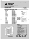
SPLIT-TYPE, HEAT PUMP AIR CONDITIONERS
SPLIT-TYPE, AIR CONDITIONERS
June 2007
No. OC370
REVISED EDITION-B
SERVICE MANUAL
Revision:
Indoor unit
[Model names]
[Service Ref.]
PLA-A12AA
PLA-A18AA
PLA-A24AA
PLA-A30AA
PLA-A36AA
PLA-A42AA
PLA-A12AA
PLA-A18AA
PLA-A24AA
PLA-A30AA
PLA-A36AA
PLA-A42AA
PLA-A12AA1
PLA-A18AA1
PLA-A24AA1
PLA-A30AA1
PLA-A36AA1
PLA-A42AA1
• WIRING DIAGRAM has been
changed in REVISED EDITION-B.
• Some descriptions have been
modified.
• Please void OC370 REVISED
EDITION-A.
NOTE:
• This manual describes only
service data of the indoor
units.
• RoHS compliant products
have <G> mark on the spec
name plate.
• For servicing RoHS compliant
products, refer to the RoHS
PARTS LIST.
CONTENTS
Model name
indication
INDOOR UNIT
ON/OFF
TEMP
TEMP.
WIRELESS REMOTE
CONTROLLER
ON/OFF
WIRED REMOTE
CONTROLLER
1. TECHNICAL CHANGES ··································2
2. REFERENCE MANUAL ······································2
3. SAFETY PRECAUTION···································3
4. PART NAMES AND FUNCTIONS ···················5
5. SPECIFICATIONS ············································8
6. NOISE CRITERION CURVES ························10
7. OUTLINES AND DIMENSIONS ·····················11
8. WIRING DIAGRAM············································12
9. REFRIGERANT SYSTEM DIAGRAM ··················13
10. TROUBLESHOOTING ···································14
11. DISASSEMBLY PROCEDURE·······················30
12. PARTS LIST ···················································33
13. RoHS PARTS LIST ········································38
33223
OC370B--1.qxp
1
07.6.20 2:42 PM
Page 2
TECHNICAL CHANGES
PLA-A12AA
PLA-A18AA
PLA-A24AA
PLA-A30AA
PLA-A36AA
PLA-A42AA
➔
➔
➔
➔
➔
➔
PLA-A12AA1
PLA-A18AA1
PLA-A24AA1
PLA-A30AA1
PLA-A36AA1
PLA-A42AA1
• Indoor controller board has been changed.
2
REFERENCE MANUAL
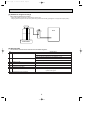
2-1. OUTDOOR UNIT SERVICE MANUAL
Service Manual No.
Service Ref.
PUZ-A18/24/30/36/42NHA
PUZ-A18/24/30/36/42NHA-BS
PUY-A12/18/24/30/36/42NHA(1)
PUY-A12/18/24/30/36/42NHA(1)-BS
OC367
2-2. TECHNICAL DATA BOOK
Manual No.
Series (Outdoor unit)
PUZ-A·NHA(-BS)
PUY-A·NHA(-BS)
OCS04
2
OC370B--1.qxp
07.6.20 2:42 PM
3
Page 3
SAFETY PRECAUTION
3-1. ALWAYS OBSERVE FOR SAFETY
Before obtaining access to terminals, all supply
circuits must be disconnected.
3-2. CAUTIONS RELATED TO NEW REFRIGERANT
Cautions for units utilising refrigerant R410A
Use new refrigerant pipes.
Do not use refrigerant other than R410A.
If other refrigerant (R22 etc.) is used, chlorine in refrigerant can cause deterioration of refrigerant oil etc.
Make sure that the inside and outside of refrigerant piping is clean and it has no contamination
such as sulfur hazardous for use, oxides, dirt,
shaving particles, etc.
In addition, use pipes with specified thickness.
Use a vacuum pump with a reverse flow check
valve.
Vacuum pump oil may flow back into refrigerant cycle and
that can cause deterioration of refrigerant oil etc.
Contamination inside refrigerant piping can cause deterioration of refrigerant oil etc.
Store the piping to be used during installation
indoors and keep both ends of the piping sealed
until just before brazing. (Leave elbow joints, etc.
in their packaging.)
If dirt, dust or moisture enters into refrigerant cycle, that can
cause deterioration of refrigerant oil or malfunction of compressor.
Use the following tools specifically designed for
use with R410A refrigerant.
The following tools are necessary to use R410A refrigerant.
Gauge manifold
Charge hose
Gas leak detector
Torque wrench
Tools for R410A
Flare tool
Size adjustment gauge
Vacuum pump adaptor
Electronic refrigerant
charging scale
Use ester oil, ether oil or alkylbenzene oil (small
amount) as the refrigerant oil applied to flares
and flange connections.
Keep the tools with care.
If large amount of mineral oil enters, that can cause deterioration of refrigerant oil etc.
If dirt, dust or moisture enters into refrigerant cycle, that can
cause deterioration of refrigerant oil or malfunction of compressor.
Charge refrigerant from liquid phase of gas
cylinder.
Do not use a charging cylinder.
If the refrigerant is charged from gas phase, composition
change may occur in refrigerant and the efficiency will be
lowered.
If a charging cylinder is used, the composition of refrigerant will change and the efficiency will be lowered.
Ventilate the room if refrigerant leaks during
operation. If refrigerant comes into contact with
a flame, poisonous gases will be released.
[1] Cautions for service
(1) Perform service after collecting the refrigerant left in the unit completely.
(2) Do not release refrigerant in the air.
(3) After completing service, charge the cycle with specified amount of refrigerant.
(4) When performing service, install a filter drier simultaneously.
Be sure to use a filter drier for new refrigerant.
3
OC370B--1.qxp
07.6.20 2:42 PM
Page 4
[2] Additional refrigerant charge
When charging directly from cylinder
· Check that cylinder for R410A on the market is syphon type.
· Charging should be performed with the cylinder of syphon stood vertically. (Refrigerant is charged from liquid phase.)
Unit
Gravimeter
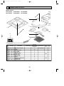
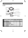
[3] Service tools
Use the below service tools as exclusive tools for R410A refrigerant.
No.
1
Specifications
Gauge manifold
·Only for R410A
·Use the existing fitting specifications. (UNF1/2)
·Use high-tension side pressure of 5.3MPa·G or over.
2
Charge hose
·Only for R410A
·Use pressure performance of 5.09MPa·G or over.
3
Electronic scale
4
Gas leak detector
·Use the detector for R134a, R407C or R410A.
5
Adaptor for reverse flow check
·Attach on vacuum pump.
6
Refrigerant charge base
7
Refrigerant cylinder
·Only for R410A
Top of cylinder (Pink)
Cylinder with syphon
8
Refrigerant recovery equipment
4
OC370B--1.qxp
07.6.20 2:42 PM
4
Page 5
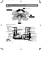
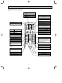
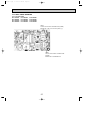
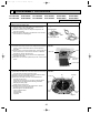
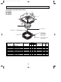
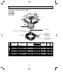
PART NAMES AND FUNCTIONS
● Indoor Unit
Filter
Removes dust and pollutants
from intake air.
Horizontal Air Outlet
Sets horizontal airflow automatically
during cooling or dehumidifying.
Grille
Auto Air Swing Vane
Disperses airflow up and
down and adjusts the angle
of airflow direction.
Air Intake
Intakes air from room.
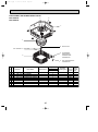
● Wired remote controller
Operation Section
ON/OFF button
Temperature setting buttons
Down
Fan Speed button
Up
Timer Menu button
(Monitor/Set button)
Filter
button
(<Enter> button)
Mode button (Return button)
TEMP.
ON/OFF
Set Time buttons
Check button (Clear button)
Back
Ahead
Test Run button
MENU
BACK
MONITOR/SET
ON/OFF
FILTER
DAY
CHECK TEST
Airflow Up/Down button
Timer On/Off button
(Set Day button)
PAR-21MAA
CLOCK
OPERATION
CLEAR
Louver button
(
Operation button)
To return operation
number
Opening the
lid
Ventilation button
( Operation button)
Built-in temperature sensor
5
To go to next operation
number
OC370B--1.qxp
07.6.20 2:42 PM
Page 6
● Wired remote controller
Display Section
For purposes of this explanation,
all parts of the display are shown
as lit. During actual operation, only
the relevant items will be lit.
Day-of-Week
“Sensor” indication
Shows the current day of the week.
Displayed when the remote controller
sensor is used.
Time/Timer Display
Shows the current time, unless the simple or Auto Off
timer is set.
If the simple or Auto Off timer is set, the time to be
switched off is shown.
“Locked” indicator
Indicates that remote controller buttons have been locked.
Identifies the current operation
“Clean The Filter” indicator
Shows the operating mode, etc.
*Multilanguage display is available.
To be displayed on when it is time to
clean the filter.
TIME SUN MON TUE WED THU FRI SAT
TIMER
Hr
ON
AFTER
AFTER OFF
ERROR CODE
FUNCTION
FILTER
˚F˚C
“Centrally Controlled” indicator
Indicates that operation from the
remote controller has been prohibited by a master controller.
˚F˚C
WEEKLY
SIMPLE
AUTO OFF
ONLY1Hr.
Timer indicators
The indicator comes on if the corresponding timer is set.
Fan Speed indicator
Shows the selected fan speed.
“Timer is Off” indicator
Indicates that the timer is off.
Up/Down Air Direction indicator
Shows the direction of the
outcoming airflow.
Room Temperature display
Shows the room temperature. The room
temperature display range is 46–102°F.
The display blinks if the temperature
is less than 46°F or 102°F or more.
Ventilation indicator
Appears when the unit is running in
Ventilation mode.
“One Hour Only” indicator
Temperature Setting
Shows the target temperature.
Displayed if the airflow is set to
Low or downward during COOL
or DRY mode. (Operation varies
according to model.)
The indicator goes off in one hour,
at which time the airflow direction
also changes.
Louver display
Indicates the action of the swing louver.
Does not appear if the louver is not
running.
(Power On indicator)
Indicates that the power is on.
Note:
● “PLEASE WAIT” message
This message is displayed for approximately 3 minutes when power is supplied to the indoor unit or when the unit is recovering from a power failure.
● “NOT AVAILABLE” message
This message is displayed if an invalid button is pressed (to operate a function that the indoor unit does not have).
If a single remote controller is used to operate multiple indoor units simultaneously that are different types, this message will not be displayed as
far as any of the indoor units is equipped with the function.
6
OC370B--1.qxp
07.6.20 2:42 PM
Page 7
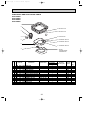
● Wireless remote controller
CHECK TEST RUN display
Indicate that the unit is being checked or
test-run.
MODEL SELECT display
display
Blinks when model is selected.
Lights up while the signal is transmitted to
the indoor unit when the button is pressed.
Temperature setting display
indicates the desired temperature setting
which is set.
CLOCK display
OPERATION MODE display
Displays the current time.
OPERATION MODE display
Indicates which operation mode is in effect.
COOL
DRY
AUTO
FAN
HEAT
display
The vertical direction of air flow is indicated.
TIMER display
CHECK TEST
MODEL RUN
SELECT
FAN
˚F
˚C
STOP AMPM
Displays when in timer operation or when
setting timer.
“
SWING
START AMPM
NOT AVAILABLE
ON/OFF
“
TEMP
”“
” display
Displays the order of timer operation.
”“
” display
Displays whether timer is on or off.
display
button
Displays selected fan speed.
Sets any desired room temperature.
ON/OFF button
The unit is turned ON and OFF alternately
each time the button is pressed.
FAN SPEED SELECT button
MODE
FAN
AUTO STOP
VANE
AUTO START
CHECK LOUVER
h
Changes the fan speed.
TEST RUN
min
MODE SELECT button
Switches the operation mode between
COOLING/DRY/FAN/HEATING and AUTO
mode.
SET
RESET
TIMER CONTROL buttons
AUTO STOP (OFF timer): when this switch
is set, the air conditioner will be automatically stopped at the preset time.
AUTO START (ON timer): when this switch
is set, the air conditioner will be automatically started at the preset time.
CLOCK
"h" and "min" buttons
wIn case the outdoor unit is cooling only
type, the heating and auto mode are not
available.
Buttons used to set the “hour and minute” of
the current time and timer settings.
LOUVER button
CHECK-TEST RUN button
Changes left / right airflow direction.
(Not available for this model.)
Performs an inspection check or test operation.
Do not use it for normal operation.
CLOCK button
VANE CONTROL button
RESET button
Changes the air flow direction.
SET button
7
OC370B--1.qxp
INDOOR UNIT
INDOOR UNIT
INDOOR UNIT
5
07.6.20 2:42 PM
Page 8
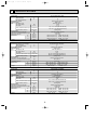
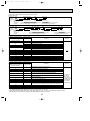
SPECIFICATIONS
Service Ref.
Power supply (phase, cycle, voltage)
Max. Fuse Size
Min. Circuit Ampacity
External finish (Panel)
Heat exchanger
Fan
Fan (drive) o No.
Fan motor output
Fan motor
Airflow (Low-Medium2-Medium1-High)
External static pressure
Booster heater
Operation control & Thermostat
Noise level (Low-Medium2-Medium1-High)
Field drain pipe O.D.
Dimensions
W
D
H
Weight
Service Ref.
Power supply (phase, cycle, voltage)
Max. Fuse Size
Min. Circuit Ampacity
External finish (Panel)
Heat exchanger
Fan
Fan (drive) o No.
Fan motor output
Fan motor
PLA-A12AA/ PLA-A12AA1
Single phase,60Hz, 208/230V
15
1
Munsell 0.70Y 8.59/0.97
Plate fin coil
Turbo fan (direct) o 1
0.070
0.79
Dry: 11-12-13-14(390-420-460-490)
Wet: 10-11-12-13(350-380-420-450)
0(direct blow)
–
Remote controller & built-in
27-28-29-31
32 (1-1/4)
PANEL : 950 (37-3/8)
UNIT : 840 (33-1/16)
PANEL : 950 (37-3/8)
UNIT : 840 (33-1/16)
PANEL : 30 (1-3/16)
UNIT : 258 (10-3/16)
PANEL: 5 (11)
UNIT : 22 (49)
A
A
kW
F.L.A.
K/min(CFM)
Pa(mmAq)
kW
dB
mm(in.)
mm(in.)
mm(in.)
mm(in.)
kg(lbs)
PLA-A18AA/ PLA-A18AA1
Single phase,60Hz, 208/230V
15
1
Munsell 0.70Y 8.59/0.97
Plate fin coil
Turbo fan (direct) o 1
0.070
0.79
Dry: 15-16-18-20(530-570-640-710)
Wet:14-15-17-19(490-530-600-670)
0(direct blow)
–
Remote controller & built-in
28-30-32-34
32 (1-1/4)
UNIT : 840 (33-1/16)
PANEL : 950 (37-3/8)
UNIT : 840 (33-1/16)
PANEL : 950 (37-3/8)
PANEL : 30 (1-3/16)
UNIT : 258 (10-3/16)
PANEL: 5 (11)
UNIT : 24 (53)
A
A
kW
F.L.A.
Airflow (Low-Medium2-Medium1-High) K/min(CFM)
External static pressure
Booster heater
Operation control & Thermostat
Noise level (Low-Medium2-Medium1-High)
Field drain pipe O.D.
Dimensions
W
D
H
Weight
Service Ref.
Power supply (phase, cycle, voltage)
Max. Fuse Size
Min. Circuit Ampacity
External finish (Panel)
Heat exchanger
Fan
Fan (drive) o No.
Fan motor output
Fan motor
Pa(mmAq)
kW
dB
mm(in.)
mm(in.)
mm(in.)
mm(in.)
kg(lbs)
PLA-A24AA/ PLA-A24AA1
Single phase,60Hz, 208/230V
15
1
Munsell 0.70Y 8.59/0.97
Plate fin coil
Turbo fan (direct) o 1
0.070
0.79
Dry: 15-16-18-20(530-570-640-710)
Wet: 14-15-17-19(490-530-600-670)
0(direct blow)
–
Remote controller & built-in
28-30-32-34
32(1-1/4)
UNIT : 840 (33-1/16)
PANEL : 950 (37-3/8)
UNIT : 840 (33-1/16)
PANEL : 950 (37-3/8)
UNIT : 258 (10-3/16)
PANEL : 30 (1-3/16)
UNIT : 24 (53)
PANEL: 5 (11)
A
A
kW
F.L.A.
Airflow (Low-Medium2-Medium1-High) K/min(CFM)
External static pressure
Booster heater
Operation control & Thermostat
Noise level (Low-Medium2-Medium1-High)
Field drain pipe O.D.
Dimensions
W
D
H
Weight
Pa(mmAq)
kW
dB
mm(in.)
mm(in.)
mm(in.)
mm(in.)
kg(lbs)
8
INDOOR UNIT
INDOOR UNIT
INDOOR UNIT
OC370B--1.qxp
07.6.20 2:42 PM
Page 9
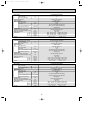
Service Ref.
Power supply (phase, cycle, voltage)
Max. Fuse Size
Min. Circuit Ampacity
External finish (Panel)
Heat exchanger
Fan
Fan (drive) o No.
Fan motor output
Fan motor
PLA-A30AA/ PLA-A30AA1
Single phase,60Hz, 208/230V
15
1
Munsell 0.70Y 8.59/0.97
Plate fin coil
Turbo fan (direct) o 1
0.070
0.79
Dry: 15-16-18-20(530-570-640-710)
Wet: 14-15-17-19(490-530-600-670)
0(direct blow)
–
Remote controller & built-in
28-30-32-34
32(1-1/4)
UNIT : 840 (33-1/16)
PANEL : 950 (37-3/8)
UNIT : 840 (33-1/16)
PANEL : 950 (37-3/8)
UNIT : 258 (10-3/16)
PANEL : 30 (1-3/16)
UNIT : 24 (53)
PANEL: 5 (11)
A
A
kW
F.L.A.
Airflow (Low-Medium2-Medium1-High) K/min(CFM)
External static pressure
Booster heater
Operation control & Thermostat
Noise level (Low-Medium2-Medium1-High)
Field drain pipe O.D.
Dimensions
W
D
H
Weight
Service Ref.
Power supply (phase, cycle, voltage)
Max. Fuse Size
Min. Circuit Ampacity
External finish (Panel)
Heat exchanger
Fan
Fan (drive) o No.
Fan motor output
Fan motor
Pa(mmAq)
kW
dB
mm(in.)
mm(in.)
mm(in.)
mm(in.)
kg(lbs)
PLA-A36AA/ PLA-A36AA1
Single phase,60Hz, 208/230V
15
2
Munsell 0.70Y 8.59/0.97
Plate fin coil
Turbo fan (direct) o 1
0.110
1.25
Dry: 20-23-26-28(710-810-920-990)
Wet: 19-22-25-27(670-770-880-950)
0(direct blow)
–
Remote controller & built-in
33-36-39-41
32(1-1/4)
UNIT : 840 (33-1/16) PANEL : 950 (37-3/8)
UNIT : 840 (33-1/16) PANEL : 950 (37-3/8)
UNIT : 298 (11-3/4) PANEL : 30 (1-3/16)
UNIT : 30 (66)
PANEL : 5 (11)
A
A
kW
F.L.A.
Airflow (Low-Medium2-Medium1-High) K/min(CFM)
External static pressure
Booster heater
Operation control & Thermostat
Noise level (Low-Medium2-Medium1-High)
Field drain pipe O.D.
Dimensions
W
D
H
Weight
Service Ref.
Power supply (phase, cycle, voltage)
Max. Fuse Size
Min. Circuit Ampacity
External finish (Panel)
Heat exchanger
Fan
Fan (drive) o No.
Fan motor output
Fan motor
Pa(mmAq)
kW
dB
mm(in.)
mm(in.)
mm(in.)
mm(in.)
kg(lbs)
PLA-A42AA/ PLA-A42AA1
Single phase,60Hz, 208/230V
15
2
Munsell 0.70Y 8.59/0.97
Plate fin coil
Turbo fan (direct) o 1
0.110
1.25
Dry: 20-23-26-28(710-810-920-990)
Wet: 19-22-25-27(670-770-880-950)
0(direct blow)
–
Remote controller & built-in
33-36-39-41
32(1-1/4)
UNIT : 840 (33-1/16) PANEL : 950 (37-3/8)
UNIT : 840 (33-1/16) PANEL : 950 (37-3/8)
UNIT : 298 (11-3/4) PANEL : 30 (1-3/16)
UNIT : 30 (66)
PANEL : 5 (11)
A
A
kW
F.L.A.
Airflow (Low-Medium2-Medium1-High) K/min(CFM)
External static pressure
Booster heater
Operation control & Thermostat
Noise level (Low-Medium2-Medium1-High)
Field drain pipe O.D.
Dimensions
W
D
H
Weight
Pa(mmAq)
kW
dB
mm(in.)
mm(in.)
mm(in.)
mm(in.)
kg(lbs)
9
OC370B--1.qxp
6
07.6.20 2:42 PM
Page 10
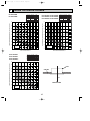
NOISE CRITERION CURVES
PLA-A12AA
PLA-A12AA1
NOTCH SPL(dB)
High
31
Medium1
29
Medium2
28
Low
27
LINE
PLA-A18AA PLA-A18AA1
PLA-A24AA PLA-A24AA1
PLA-A30AA PLA-A30AA1
80
70
NC-70
60
NC-60
50
NC-50
40
NC-40
30
NC-30
20
LINE
90
APPROXIMATE
THRESHOLD OF
HEARING FOR
CONTINUOUS
NOISE
NC-20
OCTAVE BAND SOUND PRESSURE LEVEL, dB (0 dB = 0.0002 µbar)
OCTAVE BAND SOUND PRESSURE LEVEL, dB (0 dB = 0.0002 µbar)
90
NOTCH SPL(dB)
High
34
Medium1
32
Medium2
30
Low
28
10
63
125
250
500
1000
2000
4000
80
70
NC-70
60
NC-60
50
NC-50
40
NC-40
30
NC-30
20
APPROXIMATE
THRESHOLD OF
HEARING FOR
CONTINUOUS
NOISE
10
8000
63
BAND CENTER FREQUENCIES, Hz
PLA-A36AA
PLA-A42AA
PLA-A36AA1
PLA-A42AA1
NC-20
125
250
500
1000
2000
4000
8000
BAND CENTER FREQUENCIES, Hz
NOTCH SPL(dB)
High
41
Medium1
39
Medium2
36
Low
33
LINE
OCTAVE BAND SOUND PRESSURE LEVEL, dB (0 dB = 0.0002 µbar)
90
80
UNIT
70
NC-70
CEILING
60
NC-60
50
NC-50
5 ft
40
NC-40
30
MICROPHONE
NC-30
20
APPROXIMATE
THRESHOLD OF
HEARING FOR
CONTINUOUS
NOISE
NC-20
10
63
125
250
500
1000
2000
4000
8000
BAND CENTER FREQUENCIES, Hz
10
OC370B--1.qxp
07.6.20 2:42 PM
Page 11
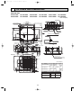
OUTLINES AND DIMENSIONS
7
INDOOR UNIT
PLA-A12AA PLA-A18AA
PLA-A30AA PLA-A36AA
PLA-A24AA
PLA-A42AA
PLA-A12AA1
PLA-A30AA1
PLA-A18AA1
PLA-A36AA1
PLA-A24AA1
PLA-A42AA1
Unit : inch(mm)
1(26)
23-13/16(605)
Branch duct hole
5-1/8(130)
Detail drawing of fresh air intake
3-[1/8([2.8)
Burring hole
6-7/32(158)
25/32~1-25/32
Feeding hole
(Drain pump)
Ceiling surface
(17
+5
0
A
4-1/8(105)
Grille
22-23/32(577)
Air intake hole
Air intake grille
+5
0
11/16
High efficiency filter
& Fresh air intake casement(option)
22-23/32(577)
Auto vane
Air intake hole
Air outlet hole
M
16-3/16(411)
(17
Drain hole
M
37-3/8(950)
+3/16
0
Ceiling surface
1-3/16(30)
9-3/4(248)
Wiring entrance holes
11/16
1-3/4(45)
7-15/32(190)
1-1/2(37)
(50~70)
Suspension bolt
lower edge
1-31/32~2-3/4
)
+3/16
0
2-[1-1/16(27)
2
)
Drain pipe
O.D.[1-1/4([32) connection
(VP-25)
14-23/32(374)
5-5/16(135)
11-1/4(286)
[3-15/16([100)
(Cut out hole)
[4-29/32([125)
B
2-3/8(60)
1
(20~45)
6-1/4(159)
33-1/16(840)
Suspension bolt
W3/8(M10)
6-11/16(170)
14-[1/8([2.8)
Burring hole
[5-29/32([150)
D
C
7-3/4(197)
5-1/2(140)
6-1/4(159)
Terminal block
3-27/32(98)
7-9/16(192)
33-1/16(840)
Branch duct hole
13-25/32(350)
[6-7/8([175)
Ceiling hole
(20~45)
Suspension bolt pitch
6-1/4(159)
6-1/4(159)
Suspension bolt pitch
Fresh air intake
25/32~1-25/32
25/32~1-25/32(20~45)
31-7/8(810)
33-27/32~35-13/16(860~910)
Ceiling hole
33-27/32~35-13/16(860~910)
25/32~1-25/32(20~45)
Branch duct hole
(Cut out hole)
3-17/32(90)
6-3/32(155)
6-9/16(167)
3-15/16(100)
3-17/32(90)
3-15/16(100)
3-15/16(100)
Unit : inch(mm)
Models
PLA-A12/18/24/30AA(1)
B
A
9-1/2 10-3/16
(241) (258)
3-1/32(77)
M
PLA-A36AA(1)
2(51)
M
16-3/16(411)
Air outlet hole
Vane motor
PLA-A42AA(1)
11-1/16 11-3/4
(298)
(281)
C
3-1/2
(89)
D
3-5/32
(80)
3-5/16
(84)
2(51)
3-1/32(77)
37-3/8(950)
11
MODEL
12/18
24/30/36/42
1 Liquid pipe
1/4F
3/8F
2 Gas pipe
1/2F
5/8F
OC370B--1.qxp
07.6.20 2:42 PM
8
Page 12
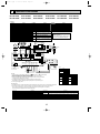
WIRING DIAGRAM
PLA-A12AA
PLA-A12AA1
[LEGEND]
SYMBOL
P.B
I.B
BCR
CN2L
CN32
CN41
CN51
FUSE
LED1
LED2
LED3
SW1
SW2
SWE
X1
X4
ZNR
PLA-A18AA
PLA-A18AA1
PLA-A24AA
PLA-A24AA1
PLA-A30AA
PLA-A30AA1
PLA-A36AA
PLA-A36AA1
PLA-A42AA
PLA-A42AA1
NAME
SYMBOL
NAME
SYMBOL
NAME
W.B
INDOOR POWER BOARD
WIRELESS REMOTE CONTROLLER BOARD
C
CAPACITOR<FAN MOTOR>
DP
BZ
INDOOR CONTROLLER BOARD
DRAIN-UP MACHINE
BUZZER
DS
FAN CONTROL ELEMENT
DRAIN SENSOR
LED1 LED<RUN INDICATOR >
H2
DEW PREVENTION HEATER
CONNECTOR<LOSSNAY>
LED2 LED<HOT ADJUST>
FAN MOTOR
RECEIVING UNIT
RU
MF
CONNECTOR<REMOTE SWITCH>
MV
VANE MOTOR
SW1
CONNECTOR<HA TERMINAL-A>
SWITCH<HEATING ON/OFF>
WIRED REMOTE CONTROLLER BOARD SW2
CONNECTOR<CENTRALLY CONTROL> R.B
SWITCH<COOLING ON/OFF>
TB4
FUSE (6.3A/250V)
TERMINAL BLOCK<INDOOR/OUTDOOR
CONNECTING LINE>
POWER SUPPLY<I.B>
TB5,TB6 TERMINAL BLOCK<REMOTE CONTROLLER
POWER SUPPLY<R.B>
Please set the voltage using the
TRANSMISSION LINE >
TRANSMISSION<INDOOR-OUTDOOR>
SWITCH <MODEL SELECTION>wSee Table 1. TH1
remote controller.
ROOM TEMP.THERMISTOR
<32°F/15kΩ, 77°F/5.2kΩ DETECT>
SWITCH <CAPACITY CODE>wSee Table 2.
For the setting method, please refer to
SWITCH<EMERGENCY OPERATION> TH2
PIPE TEMP.THERMISTOR/LIQUID
the indoor unit Installation Manual.
<32°F/15kΩ, 77°F/5.2kΩ DETECT>
RELAY<DRAIN PUMP>
TH5
COND./EVA.TEMP.THERMISTOR
RELAY<FAN MOTOR>
<32°F/15kΩ, 77°F/5.2kΩ DETECT>
VARISTOR
GRILLE
MV
MV
5
MV
5
5
MV
5
5
MF
1 2 3
P.B
3
2
1
DC
13.1V
2
1
1 2 3 6 7 4 8 9 5 10
1 2 3
CNSK
(RED)
CN2S
(WHT)
H2
YLW
ORN
TO
OUTDOOR
UNIT
S2
YLW
ORN
BRN
5
DP
TB4 w1
S1
S3
X4
BCR
X4 X1
BRN
ORN
1 3 POWER 1 2
1 3 VANE
CND
CN6V
(ORN) POWER A-CONTROL (GRN)
CN2D CN3C
(WHT) (BLU)
ZNR
X1
BLK
WHT
YLW
ORN
RED
WHT
YLW
YLW
D.U.M 1 3 D.HEATER 1 3 POWER 1 3
CNC
CNP
CNDK
(RED)
(BLU)
(RED)
FUSE
FAN 1 3 5
(WHT)
YLW
YLW
I.B
RED
WHT
BLK
C
CN51
CN41
CN2L
CN32
W.B
BZ
9
LED3 LED2 LED1
HEATER D.SENSOR INTAKE LIQUID PIPE REMOCON
CN24
CN31
CN20 CN21 CN29 CN22
(YLW) (WHT)
(RED) (WHT) (BLK) (BLU)
SWE SW2 SW1
ON
OFF
1 2
1 2
1 2
1 2
WIRELESS
CN90
(WHT)
DS
Refer to tables 1 and 2
for service PCB.
TH5
SW1
SW2
RU
1 2
TB6
TH1
TH2
LED1
R.B
BLU
BLU
1 2 3
LED2
CNB
TB5
2
1 TRANSMISSION WIRES DC12V
Table 1
MODELS
PLA-A,AA
SW1
Service board
1 2 3 4 5
ON
OFF
Table 2
NOTES:
1. Symbols used in wiring diagram above are,
: Connector,
: Terminal (block).
2. Indoor and outdoor connecting wires have polarities, make sure to match
terminal numbers (S1, S2, S3) for correct wirings.
3. Since the outdoor side electric wiring may change, be sure to check the outdoor
unit electric wiring diagram for servicing.
4. This diagram shows the wiring of Indoor and Outdoor connecting wires
(specification of 230V), adopting superimposed system of power and signal.
w1. Use copper supply wires.
MODELS
PLA-A12AA
PLA-A18AA
PLA-A24AA
SW2
Service board MODELS
Service board
1 2 3 4 5
1 2 3 4 5
1 2 3 4 5
1 2 3 4 5
ON
OFF
PLA-A30AA
ON
OFF
PLA-A36AA
ON
OFF
PLA-A42AA
1 2 3 4 5
1 2 3 4 5
ON
OFF
ON
OFF
ON
OFF
[Self-diagnosis]
1. For details on how to operate self-diagnosis with the wireless remote control, refer to the technical manuals etc.
2. For the wired remote control : When you quickly press twice the CHECK switch on the remote control,
the unit begins self-diagnosis, and Check Codes generated in the past appear on the display.
For check Codes and Symptoms refer to the table below.
Check code
P1
P2
P4
P5
P6
P8
P9
Symptom
Abnormality of room temperature thermistor(TH1)
Abnormality of pipe temperature thermistor / Liquid(TH2)
Abnormality of drain sensor(DS)
Malfunction of drain-up machine
Freezing / overheating protection is working.
Abnormality of pipe temperature
Abnormality of pipe temperature thermistor / Cond. / Eva.(TH5)
Check code
E0-E5
E6-EF
Fb
U*, F*
————
FFFF
12
Symptom
Abnormality of the signal transmission between remote
controller and indoor unit
Abnormality of the signal transmission between indoor unit and outdoor unit
Abnormality of indoor controller board
Abnormality in outdoor unit. Refer to outdoor unit wiring diagram.
No trouble generated in the past
No corresponding unit
OC370B--1.qxp
9
07.6.20 2:42 PM
Page 13
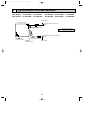
REFRIGERANT SYSTEM DIAGRAM
PLA-A12AA
PLA-A12AA1
PLA-A18AA
PLA-A18AA1
PLA-A24AA
PLA-A24AA1
PLA-A30AA
PLA-A30AA1
PLA-A36AA
PLA-A36AA1
PLA-A42AA
PLA-A42AA1
Strainer (#50)
Heat exchanger
Refrigerant GAS pipe connection
(Flare)
Thermistor TH5
(Cond./ Eva. temperature)
Refrigerant flow in cooling
Refrigerant flow in heating
Refrigerant LIQUID pipe connection
(Flare)
Thermistor TH1
(Room temperature)
Thermistor TH2
Pipe temperature (Liquid)
Distributor
with strainer (#50)
Strainer (#50)
13
OC370B--1.qxp
10
07.6.20 2:42 PM
Page 14
TROUBLESHOOTING
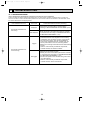
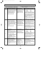
10-1. TROUBLESHOOTING
<Error code display by self-diagnosis and actions to be taken for service (summary)>
Present and past error codes are logged and displayed on the wired remote controller or controller board of outdoor unit.
Actions to be taken for service and the inferior phenomenon reoccurrence at field are summarized in the table below. Check
the contents below before investigating details.
Unit conditions at service
Error code
Actions to be taken for service (summary)
Displayed
Judge what is wrong and take a corrective action
according to “SELF-DIAGNOSIS ACTION TABLE” (10-3).
The inferior phenomenon is
reoccurring.
Not displayed
Logged
The inferior phenomenon is
not reoccurring.
Not logged
Identify the cause of the inferior phenomenon and take
a corrective action according to “TROUBLESHOOTING
BY INFERIOR PHENOMENA ” (10-4).
1Consider the temporary defects such as the work of
protection devices in the refrigerant circuit including
compressor, poor connection of wiring, noise and etc.
Re-check the symptom, and check the installation
environment, refrigerant amount, weather when the
inferior phenomenon occurred, and wiring related.
2Reset error code logs and restart the unit after finishing
service.
3There is no abnormality in electrical components,
controller boards, and remote controller.
1Recheck the abnormal symptom.
2Identify the cause of the inferior phenomenon and take
a corrective action according to “TROUBLESHOOTING
BY INFERIOR PHENOMENA ” (10-4).
3Continue to operate unit for the time being if the cause
is not ascertained.
4There is no abnormality in electrical components,
controller boards, remote controller etc.
14
OC370B--1.qxp
07.6.20 2:42 PM
Page 15
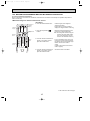
10-2. MALFUNCTION-DIAGNOSIS METHOD BY REMOTE CONTROLLER
<In case of trouble during operation>
When a malfunction occurs to the air conditioner, both indoor unit and outdoor unit will stop and operation lamp blinks to
inform unusual stop.
<Malfunction-diagnosis method at maintenance service>
[Procedure]
1. Press the CHECK button twice.
• "CHECK" lights, and refrigerant
address "00" blinks.
• Check that the remote controller's
display has stopped before continuing.
2. Press the temperature
buttons.
• Select the refrigerant address of the
indoor unit for the self-diagnosis.
Note: Set refrigerant address using the
outdoor unit’s DIP switch (SW1).
(For more information, see the
outdoor unit installation manual.)
Refrigerant
address
display
CHECK
CHECK
display
Temperature
button
TEMP
ON/OFF
ON/OFF
button
MODE
FAN
AUTO STOP
VANE
AUTO START
CHECK LOUVER
CHECK
button
min
TEST RUN
SET
h
RESET
CLOCK
HOUR
button
3. Point the remote controller at the • If an air conditioner error occurs, the
sensor on the indoor unit and
indoor unit's sensor emits an intermitpress the HOUR button.
tent buzzer sound, the operation light
flashes, and the error code is
output.
(It takes 3 seconds at most for error
code to appear.)
4. Point the remote controller at the • The check mode is cancelled.
sensor on the indoor unit and
press the ON/OFF button.
To be continued to the next page.
15
OC370B--1.qxp
07.6.20 2:42 PM
Page 16
• Refer to the following tables for details on the check codes.
[Output pattern A]
Beeper sounds
OPERATION
INDICATOR
lamp blinking
pattern
Beep
Beep Beep Beep
Off
Beep
1st
2 nd
3 rd
nth
On
On
On
On
Beep Beep
1st
Off
On
2 nd · · · Repeated
On
0.5 sec. Approx. 2.5 sec. 0.5 sec. 0.5 sec.
Self-check Approx. 2.5 sec. 0.5 sec. 0.5 sec. 0.5 sec.
starts
(Start signal
Number of blinks/beeps in pattern indicates the check
Number of blinks/beeps in pattern indicates
received)
code in the following table (i.e., n=5 for “P5”)
the check code in the following table
[Output pattern B] Only A-CONTROL
Beeper sounds
Beep
Beep Beep Beep
1st
OPERATION
INDICATOR
lamp blinking
Off
pattern
Self-check Approx. 2.5 sec.
starts
(Start signal
received)
On
Approx. 3 sec.
2nd
Beep
Beep
nth
1st
3 rd
On
On
On
0.5 sec. 0.5 sec. 0.5 sec.
On
Off
0.5 sec. Approx. 2.5 sec.
Number of blinks/beeps in pattern indicates the check
code in the following table (i.e., n=5 for “U2”)
On
Approx. 3 sec.
Beep
2 nd · · · Repeated
On
On
0.5 sec. 0.5 sec.
Number of blinks/beeps in pattern indicates
the check code in the following table
[Output pattern A] Errors detected by indoor unit
Wireless remote controller Wired remote controller
Beeper sounds/OPERATION
INDICATOR lamp blinks
1 Check code
(Number of times)
1
P1
P2
2
P9
3
E6,E7
4
P4
P5
5
PA
6
P6
7
EE
8
P8
9
E4, E5
–
10
–
11
12
Fb
E0, E3
–
–
E1, E2
Symptom
Remark
Intake sensor error
Pipe (TH2) sensor error
Pipe (TH5) sensor error
Indoor/outdoor unit communication error
Drain sensor error
Drain pump error
Forced compressor stop
Freezing/Overheating protection operation
Communication error between indoor and outdoor units
Pipe temperature error
Remote controller signal receiving error
–
–
Indoor unit control system error (memory error, etc.)
Remote controller transmission error
Remote controller control board error
[Output pattern B] Errors detected by unit other than indoor unit (outdoor unit, etc.)
Wireless remote controller Wired remote controller
Beeper sounds/OPERATION
INDICATOR lamp blinks
1 Check code
(Number of times)
1
E9
2
3
4
UP
U3,U4
UF
5
U2
6
U1,Ud
7
8
9
10
U5
U8
U6
U7
11
U9,UH
12
13
14
–
–
Others
Symptom
Indoor/outdoor unit communication error
(Transmitting error) (Outdoor unit)
Compressor overcurrent interruption
Open/short of outdoor unit thermistors
Compressor overcurrent interruption (When compressor locked)
Abnormal high discharging temperature/49C worked/
insufficient refrigerant
Abnormal high pressure (63H worked)/Overheating
protection operation
Abnormal temperature of heatsink
Outdoor unit fan protection stop
Compressor overcurrent interruption/Abnormal of power module
Abnormality of superheat due to low discharge temperature
Abnormality such as overvoltage or voltage shortage and
abnormal synchronous signal to main circuit/Current sensor error
–
–
Other errors (Refer to the technical manual for the outdoor unit.)
Remark
As for outdoor
unit, refer to
outdoor unit's
service manual.
For details, check
the LED display
of the outdoor
controller board.
*1 If the beeper does not sound again after the initial 2 beeps to confirm the self-check start signal was received and
the OPERATION INDICATOR lamp does not come on, there are no error records.
*2 If the beeper sounds 3 times continuously “beep, beep, beep (0.4 + 0.4 + 0.4 sec.)” after the initial 2 beeps to confirm
the self-check start signal was received, the specified refrigerant address is incorrect.
16
OC370B--1.qxp
07.6.20 2:42 PM
Page 17
• On wireless remote controller
The continuous buzzer sounds from receiving section of indoor unit.
Blink of operation lamp
• On wired remote controller
1Check code displayed in the LCD.
• If the unit cannot be operated properly after the test run has been performed, refer to the following table to find out the cause.
Symptom
Cause
Wired remote controller
LED 1, 2 (PCB in outdoor unit)
For about 2
After LED 1, 2 are lighted, LED 2 is •For about 2 minutes after power-on,operation
PLEASE WAIT
minutes after turned off, then only LED 1 is
of the remote controller is not possible
lighted. (Correct operation)
power-on
due to system start-up. (Correct operation)
•Connector for the outdoor unit’s protection
Only LED 1 is lighted. →
device is not connected.
PLEASE WAIT → Error code
LED 1, 2 blink. •Reverse or open phase wiring for the outdoor
Subsequent to
unit’s power terminal block (L1, L2, GR)
about 2 minutes
Display messages do not
•Incorrect wiring between indoor and outdoor
after power-on Only LED 1 is lighted. →
appear even when operation
LED 1 blinks twice, units (incorrect polarity of S1, S2, S3)
switch is turned ON (operation
LED 2 blinks once. •Remote controller wire short
lamp does not light up).
On the wireless remote controller with condition above, following phenomena take place.
• No signals from the remote controller can be received.
• Operation lamp is blinking.
• The buzzer makes a short ping sound.
Note:
Operation is not possible for about 30 seconds after cancellation of function selection. (Correct operation)
For description of each LED (LED1, 2, 3) provided on the indoor controller, refer to the following table.
LED1 (power for microcomputer)
LED2 (power for remote controller)
Indicates whether control power is supplied. Make sure that this LED is
always lit.
Indicates whether power is supplied to the remote controller.
This LED lights only in the case of the indoor unit which is connected to the
outdoor unit refrigerant address “0”.
LED3 (communication between indoor and
outdoor units)
Indicates state of communication between the indoor and outdoor units.
Make sure that this LED is always blinking.
17
OC370B--1.qxp
07.6.20 2:42 PM
Page 18
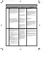
10-3. SELF-DIAGNOSIS ACTION TABLE
Error Code
P1
Abnormal point and detection method
Room temperature thermistor (TH1)
1 The unit is in 3-minute resume prevention mode if short/open of thermistor is
detected. Abnormal if the unit does not
reset normally after 3 minutes. (The
unit returns to normal operation, if it
has been reset normally.)
2 Constantly detected during cooling,
drying, and heating operation.
Short: 90:(194˚F) or more
Open: -40:(-40˚F) or less
Note: Refer to the manual of outdoor unit for the details of display
such as F, U, and other E.
Cause
1 Defective thermistor
characteristics
2 Contact failure of connector
(CN20) on the indoor controller
board (Insert failure)
3 Breaking of wire or contact
failure of thermistor wiring
4 Defective indoor controller
board
Countermeasure
1–3 Check resistance value of thermistor.
0: (32˚F)• • • • • • • • • • • 15.0k"
10:(50˚F)• • • • • • • • • • • • • 9.6k"
20:(68˚F)• • • • • • • • • • • • • 6.3k"
30:(86˚F)• • • • • • • • • • • • • 4.3k"
40:(104˚F)• • • • • • • • • • • •3.0k"
If you put force on (draw or bend) the lead wire
with measuring resistance value of thermistor
breaking of wire or contact failure can be detected.
2 Check contact failure of connector (CN20) on
the indoor controller board. Refer to 10-7.
Turn the power on again and check restart
after inserting connector again.
4 Check room temperature display on remote
controller.
Replace indoor controller board if there is abnormal difference with actual room temperature.
Turn the power off, and on again to operate
after check.
P2
Pipe temperature thermistor/Liquid
(TH2)
1 The unit is in 3-minute resume
prevention mode if short/open of
thermistor is detected. Abnormal if the
unit does not reset normally after 3 minutes. (The unit returns to normal operation, if it has been reset normally.)
2 Constantly detected during cooling,
drying, and heating (except defrosting)
operation.
Short: 90:(194˚F) or more
Open: -40:(-40˚F) or less
1 Defective thermistor
characteristics
2 Contact failure of connector
(CN21) on the indoor controller
board (Insert failure)
3 Breaking of wire or contact
failure of thermistor wiring
4 Defective refrigerant circuit is
causing thermistor temperature
of 90:(194˚F) or more or
-40:(-40˚F) or less.
5 Defective indoor controller board
1–3 Check resistance value of thermistor.
For characteristics, refer to (P1) above.
2 Check contact failure of connector (CN21) on
the indoor controller board. Refer to 10-7.
Turn the power on and check restart after
inserting connector again.
4 Check pipe <liquid> temperature with remote
controller in test run mode. If pipe <liquid>
temperature is extremely low (in cooling
mode) or high (in heating mode), refrigerant
circuit may have defect.
5 Check pipe <liquid> temperature with remote
controller in test run mode. If there is extreme
difference with actual pipe <liquid> temperature,
replace indoor controller board.
Turn the power off, and on again to operate
after check.
P4
P5
Drain sensor (DS)
1 Suspensive abnormality, if short/open of
thermistor is detected for 30 seconds
continuously.
Turn off compressor and indoor fan.
2 Short/open is detected for 30 seconds continuously during suspensive abnormality.
(The unit returns to normal operation, if
it has been reset normally.)
3 Detect the following condition.
• During cooling and drying operation
• In case that pipe <liquid> temperature
- room temperature <-10deg
(Except defrosting)
• When pipe <liquid> temperature or
room temperature is short/open temperature.
• During drain pump operation
1 Defective thermistor
1–3 Check resistance value of thermistor.
characteristics
0: (32˚F)• • • • • • • • • • • • 6.0k"
2 Contact failure of connector
10:(50˚F)• • • • • • • • • • • • 3.9k"
(CN31) on the indoor controller
20:(68˚F)• • • • • • • • • • • • 2.6k"
board (Insert failure)
30:(86˚F)• • • • • • • • • • • • 1.8k"
3 Breaking of wire or contact
40:(104˚F)• • • • • • • • • • 1.3k"
failure of drain sensor wiring
2 Check contact failure of connector (CN31) on
4 Defective indoor controller board
the indoor controller board. Refer to 10-7.
Turn the power on again and check restart
after inserting connector again.
4 Replace indoor controller board if drain
pump operates with the line of drain sensor
connector CN31-1 and 2 is short-circuited,
and abnormality reappears.
Turn the power off, and on again to operate
after check.
Malfunction of drain pump (DP)
1 Malfunction of drain pump
1 Suspensive abnormality, if thermistor
2 Defective drain
of drain sensor heats itself and
Clogged drain pump
temperature rises slightly. Turn off
Clogged drain pipe
compressor and indoor fan.
3 Attached drop of water at the
drain sensor
2 Drain pump is abnormal if the condition
above is detected during suspensive
• Drops of drain trickles from
abnormality.
lead wire.
• Clogged filter is causing
3 Constantly detected during drain pump
operation.
wave of drain.
4 Defective indoor controller board
18
1 Check if drain pump works.
2 Check drain function.
3 Check the setting of lead wire of drain sensor
and check clogs of the filter.
4 Replace indoor controller board if drain
pump operates with the line of drain sensor
connector CN31-1 and 2 is short-circuited
and abnormality reappears.
Refer to 10-7.
Turn the power off, and on again to operate
after check.
OC370B--1.qxp
07.6.20 2:42 PM
Error Code
Page 19
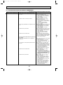
Abnormal point and detection method
Cause
Freezing/overheating protection is
working
1 Freezing protection (Cooling mode)
The unit is in 6-minute resume prevention
mode if pipe <liquid or condenser/evaporator> temperature stays under
-15:(5˚F) for 3 minutes, 3 minutes after
the compressor started. Abnormal if it
stays under -15:(5˚F) for 3 minutes
again within 16 minutes after 6-minute
resume prevention mode.
(Cooling or drying mode)
1 Clogged filter (reduced airflow)
2 Short cycle of air path
3 Low-load (low temperature)
operation out of the tolerance
range
4 Defective indoor fan motor
• Fan motor is defective.
• Indoor controller board is
defective.
5 Defective outdoor fan control
6 Overcharge of refrigerant
7 Defective refrigerant circuit
(clogs)
P6
2 Overheating protection (Heating mode)
The units is in 6-minute resume
prevention mode if pipe <condenser /
evaporator> temperature is detected as
over 70:(158˚F) after the compressor
started. Abnormal if the temperature of
over 70:(158˚F) is detected again within 10 minutes after 6-minute resume
prevention mode.
(Heating mode)
1 Clogged filter (reduced airflow)
2 Short cycle of air path
3 Overload (high temperature)
operation beyond the tolerance
range
4 Defective indoor fan motor
• Fan motor is defective.
• Indoor controller board is
defective.
5 Defective outdoor fan control
6 Overcharge of refrigerant
7 Defective refrigerant circuit
(clogs)
8 Bypass circuit of outdoor unit
is defective.
P8
Pipe temperature
<Cooling mode>
Detected as abnormal when the pipe temperature is not in the cooling range 3 minutes after compressor start and 6 minutes
after the liquid or condenser/evaporator pipe
is out of cooling range.
Note 1) It takes at least 9 minutes to
detect.
Note 2) Abnormality P8 is not detected in
drying mode.
Cooling range:-3 deg C[-5.4deg F]](TH-TH1)
TH: Lower temperature between liquid pipe
temperature (TH2) and
condenser/evaporator temperature
(TH5)
TH1: Intake temperature
<Heating mode>
When 10 seconds have passed after the
compressor starts operation and the hot
adjustment mode has finished, the unit is
detected as abnormal when
condenser/evaporator pipe temperature is
not in heating range within 20 minutes.
1 Slight temperature difference
between indoor room
temperature and pipe <liquid
or condenser / evaporator>
temperature thermistor
• Shortage of refrigerant
• Disconnected holder of pipe
<liquid or condenser /
evaporator> thermistor
• Defective refrigerant circuit
2 Converse connection of
extension pipe (on plural units
connection)
3 Converse wiring of indoor/
outdoor unit connecting wire
(on plural units connection)
4 Defective detection of indoor
room temperature and pipe
<condenser / evaporator>
temperature thermistor
5 Stop valve is not opened
completely.
Note 3) It takes at least 27 minutes to
detect abnormality.
Note 4) It excludes the period of defrosting
(Detection restarts when defrosting
mode is over)
Heating range:3 deg C[5.4deg F][(TH5-TH1)
19
Countermeasure
(Cooling or drying mode)
1 Check clogs of the filter.
2 Remove shields.
4 Measure the resistance of fan motor's winding.
Measure the output voltage of fan's connector
(FAN) on the indoor controller board.
WThe indoor controller board should be
normal when voltage of AC 208/230V is
detected while fan motor is connected.
Refer to 10-7.
5 Check outdoor fan motor.
67 Check operating condition of refrigerant
circuit.
(Heating mode)
1 Check clogs of the filter.
2 Remove shields.
4 Measure the resistance of fan motor's winding.
Measure the output voltage of fan's connector
(FAN) on the indoor controller board.
WThe indoor controller board should be
normal when voltage of AC 208/230V is
detected while fan motor is connected.
Refer to 10-7.
5 Check outdoor fan motor.
6~8Check operating condition of refrigerant
circuit.
1~4 Check pipe <liquid or condenser /
evaporator> temperature with room
temperature display on remote controller
and outdoor controller circuit board.
Pipe <liquid or condenser / evaporator>
temperature display is indicated by setting
SW2 of outdoor controller circuit board as
follows.
(
Conduct temperature check with outdoor
controller circuit board after connecting
‘A-Control Service Tool(PAC-SK52ST)’.
)
23Check converse connection of extension
pipe or converse wiring of indoor/outdoor
unit connecting wire.
OC370B--1.qxp
07.6.20 2:42 PM
Page 20
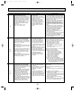
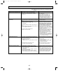
Error Code
Abnormal point and detection method
Cause
Countermeasure
P9
Pipe temperature thermistor /
Condenser-Evaporator (TH5)
1 The unit is in 3-minute resume protection mode if short/open of thermistor is
detected. Abnormal if the unit does not
get back to normal within 3 minutes.
(The unit returns to normal operation, if
it has been reset normally.)
2 Constantly detected during cooling, drying, and heating operation (except
defrosting)
Short: 90:(194˚F) or more
Open: -40:(-40˚F) or less
1 Defective thermistor
characteristics
2 Contact failure of connector
(CN29) on the indoor controller
board (Insert failure)
3 Breaking of wire or contact
failure of thermistor wiring
4 Temperature of thermistor is
90:(194˚F) or more or -40:
(-40˚F) or less caused by
defective refrigerant circuit.
5 Defective indoor controller
board
1–3 Check resistance value of thermistor.
For characteristics, refer to (P1) above.
2 Check contact failure of connector (CN29)
on the indoor controller board. Refer to 10-7.
Turn the power on and check restart after
inserting connector again.
4 Operate in test run mode and check pipe
<condenser / evaporator> temperature with
outdoor controller circuit board. If pipe
<condenser / evaporator> temperature is
extremely low (in cooling mode) or high (in
heating mode), refrigerant circuit may have
defect.
5 Operate in test run mode and check pipe
<condenser / evaporator> temperature with
outdoor control circuit board. If there is
exclusive difference with actual pipe
<condenser / evaporator> temperature
replace indoor controller board.
There is no abnormality if none of above
comes within the unit.
Turn the power off and on again to operate.
In case of checking pipe temperature
with outdoor controller circuit board,
be sure to connect A-control service
tool (PAC-SK52ST).
(
Remote controller transmission
error(E0)/signal receiving error(E4)
1 Abnormal if main or sub remote controller cannot receive any transmission
normally from indoor unit of refrigerant
address “0” for 3 minutes.
(Error code : E0)
2 Abnormal if sub-remote controller could
not receive for any signal for 2 minutes.
(Error code: E0)
E0
or
E4
E3
or
E5
1 Abnormal if indoor controller board can
not receive any data from remote controller board or normally from other
indoor controller board for 3 minutes.
(Error code: E4)
2 Indoor controller board cannot receive
any signal from remote controller for 2
minutes. (Error code: E4)
1 Contact failure at transmission
wire of remote controller
2 All remote controllers are set
as “sub” remote controller. In
this case, E0 is displayed on
remote controller, and E4 is
displayed at LED (LED1, LED2)
on the outdoor controller circuit
board.
3 Miswiring of remote controller
4 Defective transmitting receiving
circuit of remote controller
5 Defective transmitting receiving
circuit of indoor controller board
of refrigerant address “0”
6 Noise has entered into the
transmission wire of remote
controller.
1 2 remote controller are set as
“main.” (In case of 2 remote
controllers)
2 Remote controller is connected
with 2 indoor units or more.
3 Repetition of refrigerant
address
4 Defective transmitting receiving
circuit of remote controller
5 Defective transmitting receiving
circuit of indoor controller board
1 Abnormal if indoor controller board could
6 Noise has entered into transnot find blank of transmission path.
mission wire of remote controller.
(Error code: E5)
2 Indoor controller board receives transmitted data at the same time, compares
the data,and when detecting it, judges
different data to be abnormal 30
continuous times. (Error code: E5)
Remote controller transmission
error(E3)/signal receiving error(E5)
1 Abnormal if remote controller could not
find blank of transmission path for 6 seconds and could not transmit.
(Error code: E3)
2 Remote controller receives transmitted
data at the same time, compares the
data, and when detecting it, judges
different data to be abnormal 30
continuous times. (Error code: E3)
20
)
1 Check disconnection or looseness of indoor
unit or transmission wire of remote controller.
2 Set one of the remote controllers “main”
if there is no problem with the action above.
3 Check wiring of remote controller.
• Total wiring length: max. 500m
(Do not use cable o 3 or more)
• The number of connecting indoor units:
max. 16 units
• The number of connecting remote controller: max. 2 units
When the above-mentioned problem 1~3 are not seen.
4 Diagnose remote controllers.
a) When “RC OK” is displayed,
remote controllers have no problem.
Turn the power off, and on again to
check. If abnormality generates again,
replace indoor controller board.
b) When “RC NG” is displayed,
replace remote controller.
c) When “RC E3” is displayed,
d) When “ERC 00-06” is displayed,
[ c),d)→Noise may be causing abnormality. ]
∗ If the unit is not normal after replacing
indoor controller board in group control,
the indoor controller board of address
“0” may be abnormal.
1 Set a remote controller to main, and the
other to sub.
2 Remote controller is connected with only 1
indoor unit.
3 The address changes to a separate setting.
4~6 Diagnose remote controller.
a) When “RC OK” is displayed, remote controllers have no problem.
Turn the power off, and on again to check.
When becoming abnormal again, replace
indoor controller board.
b)When “RC NG” is displayed, replace
remote controller.
c)When “RC E3” or “ERC 00-66” is displayed,
noise may be causing abnormality.
OC370B--1.qxp
07.6.20 2:42 PM
Page 21
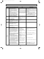
Error Code
Abnormal point and detection method
E6
Indoor/outdoor unit communication
error (Signal receiving error)
1 Abnormal if indoor controller board
cannot receive any signal normally for 6
minutes after turning the power on.
2 Abnormal if indoor controller board
cannot receive any signal normally for 3
minutes.
3 Consider the unit as abnormal under the
following condition: When 2 or more
indoor units are connected to 1
outdoor unit, indoor controller board
cannot receive a signal for 3 minutes
from outdoor controller circuit board, a
signal which allows outdoor controller
circuit board to transmit signals.
E7
Indoor/outdoor unit communication
1 Defective transmitting receiving 1-3 Turn the power off, and on again to
error (Transmitting error)
check. If abnormality generates again,
circuit of indoor controller board
Abnormal if “1” receiving is detected 30
replace indoor controller board.
2 Noise has entered into power
times continuously though indoor controller
supply.
board has transmitted “0”.
3 Noise has entered into outdoor
control wire.
Fb
Indoor controller board
Abnormal if data cannot be normally read
from the nonvolatile memory of the indoor
controller board.
E1
or
E2
PA
(2502)
(2500)
Cause
Countermeasure
1 Contact failure, short circuit or, ∗ Check LED display on the outdoor control circuit board. (Connect A-control service tool,
miswiring (converse wiring) of
PAC-SK52ST.)
indoor/outdoor unit connecting
Refer to EA-EC item if LED displays EA-EC.
wire
1 Check disconnection or looseness of indoor/
2 Defective transmitting receiving
outdoor unit connecting wire of indoor unit or
circuit of indoor controller board
outdoor unit.
3 Defective transmitting receiving
Check all the units in case of twin indoor
circuit of indoor controller board
unit system.
4 Noise has entered into indoor/ 2-4 Turn the power off, and on again to
check. If abnormality generates again,
outdoor unit connecting wire.
replace indoor controller board or outdoor
controller circuit board.
∗ Other indoor controller board may have
defect in case of twin indoor unit system.
1 Defective indoor controller
board
Remote controller control board
1 Defective remote controller
1 Abnormal if data cannot be normally
read from the nonvolatile memory of the
remote controller control board.
(Error code: E1)
1 Replace indoor controller board.
1 Replace remote controller.
2 Abnormal if the clock function of remote
controller cannot be normally operated.
(Error code: E2)
Forced compressor stop
(due to water leakage abnormality)
1 When the intake temperature subtracted
with liquid pipe temperature is less than
-10:(14˚F), drain sensor detects
whether it is soaked in the water or not
at the interval of 90 seconds. (Drain
pump will start operating when the drain
sensor detects to be soaked in the
water.)
2 The unit has a water leakage abnormality
when the following conditions, a and b,
are satisfied while the above-mentioned
detection is performed.
a) The drain sensor detects to be
soaked in the water 10 times in a row.
b) The intake temperature subtracted
with liquid pipe temperature is detected to be less than -10:(14˚F) for a
total of 30 minutes. (When the drain
sensor detects to be NOT soaked in
the water, the detection record of a
and b will be cleared.)
3 The drain sensor detection is performed
in operations other than cooling. (When
the unit stops operating, during heating
or fan operation, when the unit stops
because of some abnormality)
*Once the water leakage abnormality is
detected, abnormality state will not be
released until the main power is reset.
1 Drain pump trouble
1 Check the drain pump.
2 Drain defective
· Drain pump clogging
· Drain pipe clogging
2 Please confirm whether water can be
drained.
3 Open circuit of drain sensor
side heater
3 Confirm the resistance of the drain sensor.
4 Contact failure of drain sensor
connector
4 Check the connector contact failure.
5 Dew condensation on drain
sensor
· Drain water trickles along
lead wire.
· Drain water waving due to filter
clogging
5 Check the drain sensor leadwire mounted.
Check the filter clogging.
6 Extension piping connection
difference at twin system
6 Check the piping connection.
7 Miswiring of indoor/ outdoor
connecting at twin system
7 Check the indoor/ outdoor connecting wires.
8 Room temperature thermistor /
liquid pipe temperature thermistor detection is defective.
8 Check the room temperature display of
remote controller.
Check the indoor liquid pipe temperature
display of outdoor controller board.
21
OC370B--1.qxp
07.6.20 2:42 PM
Page 22
10-4. TROUBLESHOOTING BY INFERIOR PHENOMENA
Phenomena
(1)LED2 on indoor controller board
is off.
Note: Refer to the manual of outdoor unit for the detail of remote controller.
Cause
Countermeasure
• When LED1 on indoor controller board is also off.
1 Power supply of rated voltage is not supplied to out- 1 Check the voltage of outdoor power
door unit.
supply terminal block (L1,L2).
• When AC 208/230V is not detected,
check the power wiring to outdoor unit
and the breaker.
• When AC 208/230V is detected,
check 2 (below).
2 Check the voltage between outdoor
2 Defective outdoor controller circuit board
terminal block S1 and S2.
• When AC 208/230V is not detected.
—Check the fuse on outdoor controller
circuit board.
—Check the wiring connection.
• When AC 208/230V is detected,
check 3 (below).
3 Check the voltage between indoor terminal
3 Power supply of 208/230V is not supplied to indoor
unit.
block S1 and S2.
• When AC 208/230V is not detected,
check indoor/outdoor unit connecting
wire for miswiring.
• When AC 208/230V is detected,
check 4 (below).
4 Defective indoor power board
4 Check voltage output from CN2S on indoor
power board (DC13.1V). Refer to 10-7-1.
• When no voltage is output, check the
wiring connection.
• When output voltage is between
DC12.5V and DC13.7V, check 5
(below).
5 Check the wiring connection between
5 Defective indoor controller board
indoor controller board and indoor power
board. Check the fuse on indoor controller
board. If no problems are found, indoor
controller board is defective.
(For the separate indoor/outdoor unit power supply system)
1 Power supply of 208/230V AC is not supplied to
indoor unit.
2 The connectors of the optional replacement kit are
not used.
3 Defective indoor controller board
4 Defective indoor power board
22
1 Check the voltage of indoor power supply
terminal block (L1,L2).
• When AC208/230V is not detected,
check the power supply wiring.
• When AC208/230V is detected, check
2 (below).
2 Check that there is no problem in the
method of connecting the connectors.
• When there are problems in the method
of connecting the connectors, connect
the connector correctly referring to installation manual of an optional kit.
• When there is no problem in the
method of connecting the connectors,
check 3 (below).
3 Check voltage output from CNDK on
indoor controller board.
• When AC208/230V is not detected.
—Check the fuse on indoor controller board.
—Check the wiring connection between
indoor power supply terminal block and
CND on indoor controller board.
• When AC208/230V is detected, check
4 (below).
4 Check voltage output from CN2S on
indoor power board.
• When no voltage output, check the
wiring connection between CNDK on
indoor controller board and CNSK on
indoor power board.
If no problem are found, indoor power
board is defective.
• When DC12.5~13.7V is detected,
check the wiring connection between
CN2S on indoor power board and
CN2D on indoor power board.
If no problem are found, indoor controller board is defective.
OC370B--1.qxp
07.6.20 2:42 PM
Page 23
Note: Refer to the manual of outdoor unit for the detail of remote
controller.
Phenomena
(1)LED2 on indoor controller board
is off.
Cause
• When LED1 on indoor controller board is lit.
1 Mis-setting of refrigerant address for outdoor unit
(There is no unit corresponding to refrigerant
address “0”.)
Countermeasure
1 Check the setting of refrigerant address
for outdoor unit.
Set the refrigerant address to “0”.
(For grouping control system under
which 2 or more outdoor units are
connected, set one of the units to “0”.)
Set refrigerant address using SW1 (3-6)
on outdoor controller circuit board.
(2)LED2 on indoor controller board
is blinking.
• When LED1 on indoor controller board is also blinking. Check indoor/outdoor unit connecting wire
Connection failure of indoor/outdoor unit connecting for connection failure.
wire
• When LED1 is lit.
1 Miswiring of remote controller wires
1 Check the connection of remote conUnder twin indoor unit system, 2 indoor units are
troller wires in case of twin indoor unit
wired together.
system. When 2 indoor units are wired in
one refrigerant system, connect remote
controller wires to one of those units.
2 Refrigerant address for outdoor unit is wrong or not 2 Check the setting of refrigerant address
set.
in case of grouping control system.
Under grouping control system, there are some units
If there are some units whose refrigerant
whose refrigerant address is 0.
addresses are 0 in one group, set one of
the units to 0 using SW1 (3-6) on outdoor
controller circuit board.
3 Shortcut of remote controller wires
34 Remove remote controller wires and
4 Defective remote controller
check LED2 on indoor controller board.
• When LED2 is blinking, check the
shortcut of remote controller wires.
• When LED2 is lit, connect remote controller wires again and:
if LED2 is blinking, remote controller is
defective; if LED2 is lit, connection failure of remote controller terminal block
etc. has returned to normal.
(3)Upward/downward vane
performance failure
1 The vane is not downward during defrosting and
heat preparation and when the thermostat is OFF in
HEAT mode. (Working of COOL protection function)
2 Vane motor does not rotate.
• Defective vane motor
• Breaking of wire or connection failure of connector
1 Normal operation (The vane is set to horizontal regardless of remote control.)
3 Upward/downward vane does not work.
• The vane is set to fixed position.
3 Normal operation (Each connector on
vane motor side is disconnected.)
1 Weak batteries of wireless remote controller
1 Replace batteries of wireless remote controller.
2~4
Check contact failure of each connector.
If no problems are found of connector,
replace indoor controller board. When
the same trouble occurs even if indoor
controller board is replaced, replace
wireless remote controller board.
(4)Receiver for wireless remote
controller
2 Contact failure of connector (CNB) on wireless
remote controller board
(Insert failure)
3 Contact failure of connector (CN90) on indoor controller board (Insert failure)
4 Contact failure of connector between wireless
remote controller board and indoor controller board
23
2 Check 2 (left).
• Check the vane motor. (Refer to “How
to check the parts”.)
• Check for breaking of wire or connection failure of connector.
OC370B--1.qxp
07.6.20 2:42 PM
Page 24
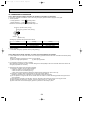
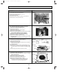
10-5. EMERGENCY OPERATION
10-5-1. When wireless remote controller has troubles or its battery is exhausted
1. Emergency operation is available in such a case using emergency operation switch equipped on the grille.
2. To start operation
• Cooling Operation·······Press
(Cooling) switch.
• Heating Operation·······Press
(Heating) switch.
wWhen the unit starts operating, the operation lamp is lit.
Emergency operation switch (cooling)
Emergency operation switch (heating)
Receiver
Operation lamp
wEmergency operation will be performed as follows.
Cooling
Mode
Set temperature
24:, 75-F
Fan speed
High
Horizontal
(30deg)
Airflow direction
Heating
24:, 75-F
High
Downward (70deg)
3. To stop operation
• Press either emergency operation switch (cooling/heating).
10-5-2. When wired remote controller or indoor unit microcomputer has troubles
1. If other defects are not found when trouble occurs, emergency operation starts as the indoor controller board switch (SWE)
is set to ON.
During the emergency operation, the indoor unit is as follows;
(1) Indoor fan high speed operation
(2) Drain pump operation
2. For emergency operation of cooling or heating
When emergency operation for COOL or HEAT, setting of the switch (SWE) in the indoor controller board and outdoor unit
emergency operation are necessary.
3. Check items and notices as the emergency operation
(1) Emergency operation cannot be used as follows;
• When the outdoor unit is something wrong.
• When the indoor fan is something wrong.
• When drain overflow protection operation is detected during self-diagnosis. (Error code : P5)
(2) Emergency operation will be serial operation by the power supply ON/OFF.
ON/OFF or temperature, etc. adjustment is not operated by the remote controller.
(3) Do not operate for a long time as cold air is blown when the outdoor unit starts defrosting operation during heat emergency operation.
(4) Cool emergency operation must be within 10 hours. Otherwise, heat exchanger of indoor unit may get frosted.
(5) After completing the emergency operation, return the switch setting, etc. in former state.
(6) Since vane does not work at emergency operation, position the vane slowly by hand.
24
OC370B--1.qxp
07.6.20 2:42 PM
Page 25
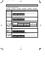
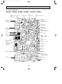
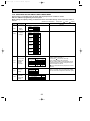
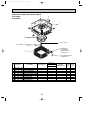
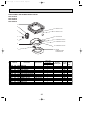
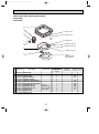
10-6. HOW TO CHECK THE PARTS
PLA-A12AA PLA-A18AA
PLA-A24AA
PLA-A12AA1 PLA-A18AA1 PLA-A24AA1
PLA-A30AA
PLA-A30AA1
Parts name
Pipe temperature
thermistor/liquid(TH2)
Condenser/Evaporator
temperature thermistor
(TH5)
Vane motor (MV)
Disconnect the connector then measure the resistance using a tester.
(At the ambient temperature 10:(50˚F)~30:(86˚F))
Normal
Abnormal
4.3k"~9.6k"
Open or short
Normal
Abnormal
15k"
Open or short
Measure the resistance between the terminals using a tester.
(Winding temperature 20:(68˚F))
Relay connector
Red
3 Black
(Refer to the thermistor characteristic graph.)
Measure the resistance between the terminals using a tester.
(At the ambient temperature20:(68˚F))
Fan motor (MF)
2 White
PLA-A42AA
PLA-A42AA1
Check points
Room temperature
thermistor
(TH1)
1
PLA-A36AA
PLA-A36AA1
1
2
3
Motor terminal
or
Relay connector
Normal
PLA-A12/18/24/30AA
PLA-A12/18/24/30AA1
PLA-A36/42AA
PLA-A36/42AA1
Red-Black
87.2"
32.6"
White-Black
104.1"
40.7"
Abnormal
Open or short
Protector
OFF:130:
ON :80i20:
Drain pump (DP)
Measure the resistance between the terminals using a tester.
(Winding temperature 20:(68˚F))
YLW
1
Normal
Abnormal
3
319"
Open or short
YLW
Drain sensor (DS)
1
2
3
Measure the resistance between the terminals using a tester.
Measure the resistance after 3 minutes have passed since the power supply was intercepted.
(At the ambient temperature 0:(32˚F)~60:(140˚F))
Normal
Abnormal
0.6k"~6.0k"
Open or short
25
(Refer to the thermistor characteristic graph.)
OC370B--1.qxp
07.6.20 2:42 PM
Page 26
<Thermistor Characteristic graph>
Room temperature thermistor(TH1)
Thermistor for
lower temperature Pipe temperature thermistor/liquid(TH2)
Condenser/evaporator temperature
thermistor(TH5)
<Thermistor for lower temperature>
50
40
1
273+t
t(:):Rt=15exp { 3480(
T(˚F):Rt=15exp { 3480(
0: (32˚F)
10: (50˚F)
20: (68˚F)
25: (77˚F)
30: (86˚F)
40:(104˚F)
1
273+ T-32
1.8
Resistance (k")
Thermistor R0=15k' ± 3%
Fixed number of B=3480 ± 2%
1
)}
273
30
20
1
)}
273
10
15k'
9.6k'
6.3k'
5.4k'
4.3k'
3.0k'
0
-20 -10 0 10 20 30 40 50 :
-4 -14 32 50 68 86 104 122 °F
Temperature
Thermistor for
drain sensor
10
< Thermistor for drain sensor >
9
8
Thermistor R0=6.0k' ±5%
Fixed number of B=3390 ±2%
1
273+t
1
T(˚F):Rt=6exp { 3390(
273+ T-32
1.8
Resistance (k")
t(:)Rt= 6 exp { 3390(
7
1
)}
273
1
)}
273
6
5
4
3
0: (32˚F)
10: (50˚F)
20: (68˚F)
25: (77˚F)
30: (86˚F)
40:(104˚F)
60:(140˚F)
6.0k'
3.9k'
2.6k'
2.2k'
1.8k'
1.3k'
0.6k'
2
1
0
-20
-4
26
0
32
20 40 60 80
68 104 140 176
Temperature
:
°F
OC370B--1.qxp
07.6.20 2:42 PM
Page 27
10-7.TEST POINT DIAGRAM
10-7-1. Power
PLA-A12AA
PLA-A30AA
PLA-A12AA1
PLA-A30AA1
board
PLA-A18AA
PLA-A36AA
PLA-A18AA1
PLA-A36AA1
PLA-A24AA
PLA-A42AA
PLA-A24AA1
PLA-A42AA1
CN2S
Connect to the indoor controller board (CN2D)
between 1 to 3 12.6-13.7V DC (Pin1 (+))
CNSK
Connect to the indoor controller board
(CNDK)
between 1 to 3 208/230V AC
27
OC370B--1.qxp
07.6.20 2:42 PM
Page 28
10-7-2. Indoor controller board
PLA-A12AA PLA-A18AA PLA-A24AA
PLA-A12AA1 PLA-A18AA1 PLA-A24AA1
CN2D
Connect to the indoor power board
(CN2S)
(12.5~13.7V DC)
PLA-A30AA
PLA-A30AA1
LED1
Power supply (I.B)
PLA-A36AA
PLA-A36AA1
LED2
Power supply (R.B)
PLA-A42AA
PLA-A42AA1
LED3
Transmission (Indoor/outdoor)
CN22
Connect to the terminal
block(TB5)
(Remote controller connecting
wire)
(10.4~14.6V DC)
CN3C
Transmission
(Indoor/outdoor)
(0~24V DC)
CN20
Room temperature
thermistor (TH1)
CN21
Pipe temperature
thermistor/Liquid (TH2)
CNDK
Connect to the indoor
power board (CNSK)
(208/230V AC)
CN29
Condenser/evaporator
temperature thermistor (TH5)
FUSE
(6.3 A 250 V)
CN31
Drain sensor (DS)
CND
Power supply input
(208/230V AC)
CN90
Connect to the wireless
remote controller board
(CNB)
CN6V
Vane motor output
(MV)
CNP
Drain-pump output
(DP)
(208/230V AC)
CN41
Connector (HA terminal-A)
CNC
Dew prevention
heater (H2)
(208/230V AC)
CN51
Centrally control
CN24
Heater output
(12V DC)
CN32
Remote switch
CN2L
Connector
(LOSSNAY)
SWE
Emergency operation
Jumper wire J41, J42
Pair number setting with
wireless remote controller
FAN
Fan motor output
SW2
Capacity setting
SW1
Model setting
28
OC370B--1.qxp
07.6.20 2:42 PM
Page 29
10-8. FUNCTIONS OF DIP SWITCH AND JUMPER WIRE
Each function is controlled by the dip switch and the jumper wire on control P.C. board.
SW1 and SW2 are equipped only for service parts.
Model setting and capacity setting are memorized in the nonvolatile memory of the control P.C. board of
the unit.
(Marks in the table below)
Jumper wire
Functions
Setting by the dip switch and jumper wire
MODELS
Model
settings
PLA-A·AA
PLA-A·AA1
SW2
Capacity
settings
MODELS
Service board
PLA-A12AA
PLA-A12AA1
1 2 3 4 5
PLA-A18AA
PLA-A18AA1
1 2 3 4 5
PLA-A24AA
PLA-A24AA1
1 2 3 4 5
PLA-A30AA
PLA-A30AA1
1 2 3 4 5
PLA-A36AA
PLA-A36AA1
1 2 3 4 5
PLA-A42AA
PLA-A42AA1
1 2 3 4 5
J41
J42
JP1
Unit type
setting
JP3
Indoor
controller
board type
setting
: Short
: Open)
Remarks
Service board
1 2 3 4 5
SW1
Pair number
setting with
wireless
remote
controller
Jumper wire (
ON
OFF
ON
OFF
ON
OFF
ON
OFF
ON
OFF
ON
OFF
ON
OFF
Wireless remote Control PCB setting
controller setting
J41
J42
0
1
2
3~9
Model
Without TH5
With TH5
JP1
Indoor controller board type
For product
Service parts
<Initial setting>
Wireless remote controller: 0
Control PCB: (for both J41 and J42)
4 pair number settings are supported.
The pair number settings of the wireless remote
controller and indoor control PCB (J41/J42) are
given in the table on the left.
(' ' in the table indicates the jumper wire is disconnected.)
There is no jumper (JP1) because these models
have the cond./eva. temperature thermistor (TH5).
JP3
29
OC370B--1.qxp
11
07.6.20 2:42 PM
Page 30
DISASSEMBLY PROCEDURE
PLA-A12AA
PLA-A12AA1
PLA-A18AA
PLA-A18AA1
PLA-A24AA
PLA-A24AA1
PLA-A30AA
PLA-A30AA1
PLA-A36AA
PLA-A36AA1
PLA-A42AA
PLA-A42AA1
Be careful on removing heavy parts.
OPERATING PROCEDURE
PHOTOS & ILLUSTRATIONS
1. Removing the air intake grille
(1) Slide the knob of air intake grille to the direction of the
arrow 1 to open the air intake grille.
(2) Remove the string hook from the panel to prevent the
grille from dropping.
(3) Slide the shaft in the hinge to the direction of the arrow2
and remove the air intake grille.
Figure 1
Air intake grille
Grille
Air intake grille knob
2. Removing the room temperature thermistor
(1) Remove the screw(✕1) in the room temperature thermistor
holder to remove the holder and the room temperature
thermistor.
(2) Remove the 1 screw from the bell mouth, and unscrew the
other 2 screws (fix to the oval hole which has a different
diameter) to remove the bell mouth.
(3) Hold the holder claw, and remove the room temperature
thermistor and holder.
(4) Disconnect the connector (CN20:red) on the indoor control
board.
Photo 1
Screws
Bell mouth
Room
temperature
thermistor
Air intake grille
3. Removing the electrical box
Photo 2
(1) Disconnect the lead wire of the vane motor from the clamp,
and disconnect the white connector (10P).
(2) Remove the room temperature thermistor with the holder.
Turbo fan
(3) Remove the bell mouth.(See photo 1)
(4) Disconnect the relay connector in the electrical box.
Red (3P) for fan motor
Disconnect the connector on the indoor controller board.
Electrical
White (2P) for pipe temperature detecting thermistor
box
Blue (3P) for drain pump
White (3P) for drain sensor
(5) Remove the 3 screws from the electrical box, loosen
another 2 screws to remove the box.
<Electrical parts in the electrical box>
Indoor controller board
Power
Power board
board
Terminal block
Capacitor
30
Nut
Capacitor
Terminal
block
Indoor controller board
Connector
OC370B--2.qxp
07.6.20 2:41 PM
Page 31
OPERATING PROCEDURE
PHOTOS & ILLUSTRATIONS
4. Removing the fan motor
(1) Remove the bell mouth.(See photo 1)
(2) Remove the electrical box.(See photo 2)
(3) Remove the turbo fan nut.
(4) Pull out the turbo fan.
(5) Disconnect the connector of the fan motor lead wire.
(6) Remove the 4 nuts of the fan motor.
Fan motor
Photo 3
Nut
Connector
Nut
5. Removing the pipe temperature thermistor
and condenser evaporator temperature thermistor
(1) Remove the bell mouth.(See photo 1)
(2) Remove the electrical box.(See photo 2)
(3) Remove the turbo fan.
(4) Remove the screw of the service panel.
(5) Remove the service panel.
(6) Remove the pipe temperature thermistor which is inserted
into the holder installed to the thin copper pipe.
(7) Disconnect the 2-pin white connector.(CN21)
[Condenser/ evaporator temperature thermistor]
(8) Remove the drain pan. (See Photo 6)
(9) Remove the thermistor which is installed into the holder to
the indoor coil.
(10) Disconnect the 2-pin black connector. (CN29)
Photo 4
6. Removing the panel
(1) Remove the air intake grille.(See figure 1)
Corner panel (See figure 2)
(1) Remove the corner screw.
(2) Slide the corner panel to the direction of the arrow3, and
remove the corner panel.
Panel (See photo 5)
(1) Disconnect the connector that connects with the unit.
(2) Remove the 2 screws from the panel and loosen another
2 screws, which fix to the oval holes, have different diameters.
(3) Rotate the panel a little to remove the screws.
Figure 2
7. Removing the drain pan
(1) Remove the panel. (See photo 5)
(2) Remove the drain plug (Larger one), drain the remaining
water in the drain pan.
(3) Remove the corner cover. (2 screws)
(4) Remove the bell mouth (See photo 1)
(5) Remove the electrical box. (See photo 2)
(6) Remove the lead wire holder. (1 screw)
(7) Remove the 4 screws and pull out the drain pan.
w Pull out the left and right of the pan gradually.
Be careful not to crack or damage the pan.
31
Pipe temperature thermistor
Service access
Screw
Corner
panel
Panel
Corner
panel
Photo 5
Connector
Screw
Panel
Screw
Photo 6
Screw
Screw
Drain pan
Screw
Lead
wire
holder
Screw
Drain plug(Larger one)
Corner cover
OC370B--2.qxp
07.6.20 2:41 PM
Page 32
OPERATING PROCEDURE
PHOTOS & ILLUSTRATIONS
8. Removing the drain pump and drain sensor
(1) Remove the panel. (See photo 5)
(2) Remove the bell mouth. (See photo 1)
(3) Remove the electrical box. (See photo 2)
(4) Remove the drain pan. (See photo 6)
(5) Remove the 3 screws of the drain pump.
(6) Cut the drain hose band, pull out the drain hose from the
drain pump.
(7) Pull out the drain pump.
(8) Remove the drain sensor and the holder.
Photo 7
Drain sensor
Screw
Drain hose
Fixing band
Screw
Drain pump
9. Removing the heat exchanger
(1) Remove the panel. (See photo 5)
(2) Remove the bell mouth. (See photo 1)
(3) Remove the electrical box. (See photo 2)
(4) Remove the drain pan. (See photo 6)
(5) Remove the turbo fan. (See photo 3)
(6) Remove the 3 screws of the piping cover, and pull out
piping cover.
(7) Remove the 4 screws of the outer wall cover, and pull out
the outer wall cover.
(8) Remove the screw of the coil support.
(9) Remove the 2 screws of the coil.
(10) Pull out the heat exchanger.
Photo 8
Coil support
Coil screws
Heat exchanger
Coil
support
Coil
support
Photo 9
Screw
Outer wall cover
32
Piping cover
Screws of
piping cover
OC370B--2.qxp
07.6.20 2:41 PM
12
Page 33
PARTS LIST (non-RoHS compliant)
PANEL PARTS
PLA-A12AA PLA-A18AA
PLA-A30AA PLA-A36AA
PLA-A24AA
PLA-A42AA
GEAR
9
GEAR
(VANE)
8
VANE
BUSH
2
7
6
VANE
MOTOR
3
1
3
3
4
10
5
11
CENTRALLY CONTROLLED
ON
1Hr.
OFF
˚C
CLOCK
CHECK
FILTER
CHECK MODE
TEST RUN
FUNCTION
˚C
STAND BY
DEFROST
ERROR CODE
TEMP.
NOT AVAILABLE
ON/OFF
Part number that is circled is not shown in the figure.
Q'ty / set
No.
Parts No.
T7W
T7W
R01
R01
R01
R01
R01
R01
R01
T7W
T7W
12 R01
1
2
3
4
5
6
7
8
9
10
11
E13
E05
E03
E00
E00
E00
E00
E00
E01
E10
E01
E00
003
002
638
500
691
223
063
040
040
713
305
673
Parts Name
Specification
PLA-A12/18/24
/30/36/42AA
1
4
4
1
1
4
8
4
4
1
1
1
AIR OUTLET GRILLE
VANE
CORNER PANEL
L.L FILTER
GRILLE ASSY
VANE MOTOR
VANE BUSH
GEAR (VANE)
GEAR
REMOTE CONTROLLER
CABLE ASSY
SCREW ASSY
33
Remarks
(Drawing No.)
Wiring RecomDiagram mended
Symbol
Q'ty
Including H2
MV
R.B
OC370B--2.qxp
07.6.20 2:41 PM
Page 34
FUNCTIONAL AND STRUCTURAL PARTS
PLA-A12AA
PLA-A18AA
PLA-A24AA
PLA-A30AA
9
8
7
1
6 MOTOR CAP
SPL WASHER 2
5 CONDENSER
EVAPORATOR
TEMPERATURE
THERMISTOR
3
4 PIPE TEMPERATURE
THERMISTOR
No.
Parts No.
1 R01
2 R01
T7W
3 T7W
T7W
4 T7W
5 R01
6 R01
7 T7W
8 T7W
9 R01
E28
08K
H20
H34
H21
E06
E32
E00
E01
E12
A41
114
097
480
480
480
202
202
122
304
762
105
Parts Name
Specification
TURBO FAN
SPL WASHER
HEAT EXCHANGER
HEAT EXCHANGER
HEAT EXCHANGER
PIPE TEMPERATURE THERMISTOR
CONDENSER / EVAPORATOR TEMPERATURE THERMISTOR
MOTOR CAP
LEAD ASSY(F/M)
D17D6P70MS
FAN MOTOR
RUBBER MOUNT
34
Q'ty / set
PLA-A·AA
12
18
24, 30
1
1
1
1
1
1
1
Remarks
(Drawing No.)
Wiring RecomDiagram mended
Symbol
Q'ty
1
1
1
1
1
1
4
1
1
1
1
1
4
1
1
1
1
1
1
4
TH2
TH5
MF
OC370B--2.qxp
07.6.20 2:41 PM
Page 35
FUNCTIONAL AND STRUCTURAL PARTS
PLA-A36AA
9
PLA-A42AA
8
7
1
6 MOTOR CAP
SPL WASHER 2
5 CONDENSER
EVAPORATOR
TEMPERATURE
THERMISTOR
3
4 PIPE TEMPERATURE
THERMISTOR
No.
Parts No.
Parts Name
Specification
Q'ty / set
PLA-A·AA
36, 42
1
2
3
4
5
6
7
8
9
T7W
R01
T7W
T7W
R01
R01
T7W
T7W
R01
E02
08K
H22
E06
E32
E00
E01
E08
A41
114
097
480
202
202
122
304
762
105
TURBO FAN
SPL WASHER
HEAT EXCHANGER
PIPE TEMPERATURE THERMISTOR
CONDENSER / EVAPORATOR TEMPERATURE THERMISTOR
MOTOR CAP
LEAD ASSY(F/M)
FAN MOTOR
RUBBER MOUNT
D17CP110MS
35
1
1
1
1
1
1
1
1
4
Remarks
(Drawing No.)
Wiring
Diagram
Symbol
TH2
TH5
MF
Recommended
Q'ty
OC370B--2.qxp
07.6.20 2:41 PM
Page 36
FUNCTIONAL AND STRUCTURAL PARTS
PLA-A12AA
PLA-A18AA
PLA-A24AA
PLA-A30AA
1
2
14 DRAIN PLUG
3
13 DRAIN PLUG
4
12 CAPACITOR
5
11 TERMINAL BLOCK
10 TERMINAL BLOCK
6
9 TERMINAL BLOCK
7
8 ROOM
TEMPERATURE
THERMISTOR
Q'ty / set
No.
1
2
3
4
5
6
7
8
9
10
11
12
13
14
Parts No.
T7W E09
T7W E00
T7W E12
R01 E00
R01 31K
T7W E24
T7W E46
R01 E00
R01 556
R01 E13
T7W E11
T7W E10
R01 A41
R01 A48
Parts Name
529
527
355
266
241
313
310
202
246
246
716
255
524
524
DRAIN PAN
DRAIN HOSE
DRAIN PUMP
DRAIN SENSOR
SENSOR HOLDER
INDOOR POWER BOARD
INDOOR CONTROLLER BOARD
ROOM TEMPERATURE THERMISTOR
TERMINAL BLOCK
TERMINAL BLOCK
TERMINAL BLOCK
CAPACITOR
DRAIN PLUG
DRAIN PLUG
Specification
2P (1, 2)
3P (S1, S2, S3)
3P (L1, L2, GR)
3.0+ 440V
36
PLA-A·AA
12, 18, 24, 30
1
1
1
1
1
1
1
1
1
1
1
1
1
1
Remarks
(Drawing No.)
Wiring RecomDiagram mended
Symbol
Q'ty
DP
DS
P.B
I.B
TH1
TB5
TB4
TB2
C
OC370B--2.qxp
07.6.20 2:41 PM
Page 37
FUNCTIONAL AND STRUCTURAL PARTS
PLA-A36AA
PLA-A42AA
1
2
14 DRAIN PLUG
3
13 DRAIN PLUG
4
12 CAPACITOR
5
11 TERMINAL BLOCK
10 TERMINAL BLOCK
6
9 TERMINAL BLOCK
7
8
ROOM
TEMPERATURE
THERMISTOR
Q'ty / set
No.
1
2
3
4
5
6
7
8
9
10
11
12
13
14
Parts No.
T7W E07
T7W E00
T7W E12
R01 E00
R01 31K
T7W E24
T7W E46
R01 E00
R01 556
R01 E13
T7W E11
R01 E03
R01 A41
R01 A48
529
527
355
266
241
313
310
202
246
246
716
255
524
524
Parts Name
DRAIN PAN
DRAIN HOSE
DRAIN PUMP
DRAIN SENSOR
SENSOR HOLDER
INDOOR POWER BOARD
INDOOR CONTROLLER BOARD
ROOM TEMPERATURE THERMISTOR
TERMINAL BLOCK
TERMINAL BLOCK
TERMINAL BLOCK
CAPACITOR
DRAIN PLUG
DRAIN PLUG
Specification
2P (1, 2)
3P (S1,S2, S3)
3P (L1,L2, GR)
7.0+ 440V
37
PLA-A·AA
36, 42
1
1
1
1
1
1
1
1
1
1
1
1
1
1
Remarks
(Drawing No.)
Wiring RecomDiagram mended
Symbol
Q'ty
DP
DS
P.B
I.B
TH1
TB5
TB4
TB2
C
OC370B--2.qxp
07.6.20 2:41 PM
13
Page 38
RoHS PARTS LIST
PANEL PARTS
PLA-A12AA1 PLA-A18AA1
PLA-A30AA1 PLA-A36AA1
PLA-A24AA1
PLA-A42AA1
GEAR
9
GEAR
(VANE)
8
VANE
BUSH
2
7
6
VANE
MOTOR
3
1
3
3
10
4
5
11
CENTRALLY CONTROLLED
ON
1Hr.
OFF
˚C
CLOCK
CHECK
˚C
STAND BY
DEFROST
ERROR CODE
TEMP.
NOT AVAILABLE
FILTER
CHECK MODE
TEST RUN
FUNCTION
ON/OFF
No.
1
2
3
4
5
6
7
8
9
10
11
RoHS
Part number that is circled is not shown in the figure.
G
G
G
G
G
G
G
G
G
G
G
12 G
Q'ty / set
Parts No.
T7W
T7W
R01
R01
R01
R01
R01
R01
R01
T7W
T7W
R01
E19
E09
E14
E13
E44
E17
E02
E03
E04
E14
E04
E02
003
002
638
500
691
223
063
040
040
713
305
673
Parts Name
Specification
PLA-A12/18/24
/30/36/42AA1
1
4
4
1
1
4
8
4
4
1
1
1
AIR OUTLET GRILLE
VANE
CORNER PANEL
L.L FILTER
GRILLE ASSY
VANE MOTOR
VANE BUSH
GEAR (VANE)
GEAR
REMOTE CONTROLLER
CABLE ASSY
SCREW ASSY
38
Remarks
(Drawing No.)
Wiring
Diagram
Symbol
Including H2
MV
R.B
Recommended
Q'ty
OC370B--2.qxp
07.6.20 2:41 PM
Page 39
FUNCTIONAL AND STRUCTURAL PARTS
PLA-A12AA1
PLA-A18AA1
PLA-A24AA1
PLA-A30AA1
9
8
7
1
6 MOTOR CAP
SPL WASHER 2
5 CONDENSER
EVAPORATOR
TEMPERATURE
THERMISTOR
3
4 PIPE TEMPERATURE
No.
RoHS
THERMISTOR
Q'ty / set
Parts No.
1 G R01
2 G R01
G T7W
3 G T7W
G T7W
4 G R01
5 G R01
6 G R01
7 G T7W
8 G T7W
9 G R01
E28
09K
H20
H34
H21
H05
H15
E03
E05
E27
A51
114
097
480
480
480
202
202
122
304
762
105
Parts Name
Specification
TURBO FAN
SPL WASHER
HEAT EXCHANGER
HEAT EXCHANGER
HEAT EXCHANGER
PIPE TEMPERATURE THERMISTOR
CONDENSER / EVAPORATOR TEMPERATURE THERMISTOR
MOTOR CAP
LEAD ASSY (F/M)
D17D6P70MS
FAN MOTOR
RUBBER MOUNT
39
PLA-A·AA1
12
1
1
1
18 24, 30
1
1
1
1
Remarks
(Drawing No.)
Wiring RecomDiagram mended
Symbol
Q'ty
1
1
1
1
1
1
4
1
1
1
1
1
4
1
1
1
1
1
1
4
TH2
TH5
MF
OC370B--2.qxp
07.6.20 2:41 PM
Page 40
FUNCTIONAL AND STRUCTURAL PARTS
PLA-A36AA1
9
PLA-A42AA1
8
7
1
6 MOTOR CAP
SPL WASHER 2
5 CONDENSER
EVAPORATOR
TEMPERATURE
THERMISTOR
3
4 PIPE TEMPERATURE
No.
RoHS
THERMISTOR
1
2
3
4
5
6
7
8
9
G
G
G
G
G
G
G
G
G
Q'ty / set
Parts No.
Parts Name
Specification
PLA-A·AA1
36, 42
R01
R01
T7W
R01
R01
R01
T7W
T7W
R01
E29
09K
H22
H05
H15
E03
E05
E28
A51
114
097
480
202
202
122
304
762
105
TURBO FAN
SPL WASHER
HEAT EXCHANGER
PIPE TEMPERATURE THERMISTOR
CONDENSER / EVAPORATOR TEMPERATURE THERMISTOR
MOTOR CAP
LEAD ASSY(F/M)
FAN MOTOR
RUBBER MOUNT
D17CP110MS
40
1
1
1
1
1
1
1
1
4
Remarks
(Drawing No.)
Wiring RecomDiagram mended
Symbol
Q'ty
TH2
TH5
MF
OC370B--2.qxp
07.6.20 2:41 PM
Page 41
FUNCTIONAL AND STRUCTURAL PARTS
PLA-A12AA1
PLA-A18AA1
PLA-A24AA1
PLA-A30AA1
1
2
14 DRAIN PLUG
3
13 DRAIN PLUG
4
12 CAPACITOR
5
11 TERMINAL BLOCK
10 TERMINAL BLOCK
6
9 TERMINAL BLOCK
7
8 ROOM
No.
RoHS
TEMPERATURE
THERMISTOR
1
2
3
4
5
6
7
8
9
10
11
12
13
14
G
G
G
G
G
G
G
G
G
G
G
G
G
G
Q'ty / set
Parts No.
T7W
T7W
T7W
R01
R01
T7W
T7W
R01
R01
R01
T7W
T7W
R01
R01
E26
E02
E12
E10
32K
E35
E56
H12
E21
E18
E41
E15
A00
A01
529
527
355
266
241
313
310
202
246
246
716
255
524
524
Parts Name
DRAIN PAN
DRAIN HOSE
DRAIN PUMP
DRAIN SENSOR
SENSOR HOLDER
INDOOR POWER BOARD
INDOOR CONTROLLER BOARD
ROOM TEMPERATURE THERMISTOR
TERMINAL BLOCK
TERMINAL BLOCK
TERMINAL BLOCK
CAPACITOR
DRAIN PLUG
DRAIN PLUG
Specification
2P (1, 2)
3P (S1, S2, S3)
3P (L1, L2, GR)
3.0+ 440V
41
PLA-A·AA1
12, 18, 24, 30
1
1
1
1
1
1
1
1
1
1
1
1
1
1
Remarks
(Drawing No.)
Wiring RecomDiagram mended
Symbol
Q'ty
DP
DS
P.B
I.B
TH1
TB5
TB4
TB2
C
OC370B--2.qxp
07.6.20 2:41 PM
Page 42
FUNCTIONAL AND STRUCTURAL PARTS
PLA-A36AA1
PLA-A42AA1
1
2
14 DRAIN PLUG
3
13 DRAIN PLUG
4
12 CAPACITOR
5
11 TERMINAL BLOCK
10 TERMINAL BLOCK
6
9 TERMINAL BLOCK
No.
RoHS
7
1
2
3
4
5
6
7
8
9
10
11
12
13
14
G
G
G
G
G
G
G
G
G
G
G
G
G
G
8
ROOM
TEMPERATURE
THERMISTOR
Q'ty / set
Parts No.
T7W
T7W
T7W
R01
R01
T7W
T7W
R01
R01
R01
T7W
R01
R01
R01
E28
E02
E12
E10
32K
E35
E56
H12
E21
E18
E41
E14
A00
A01
529
527
355
266
241
313
310
202
246
246
716
255
524
524
Parts Name
DRAIN PAN
DRAIN HOSE
DRAIN PUMP
DRAIN SENSOR
SENSOR HOLDER
INDOOR POWER BOARD
INDOOR CONTROLLER BOARD
ROOM TEMPERATURE THERMISTOR
TERMINAL BLOCK
TERMINAL BLOCK
TERMINAL BLOCK
CAPACITOR
DRAIN PLUG
DRAIN PLUG
Specification
2P (1, 2)
3P (S1,S2, S3)
3P (L1,L2, GR)
7.0+ 440V
42
PLA-A·AA1
36, 42
1
1
1
1
1
1
1
1
1
1
1
1
1
1
Remarks
(Drawing No.)
Wiring RecomDiagram mended
Symbol
Q'ty
DP
DS
P.B
I.B
TH1
TB5
TB4
TB2
C
OC370B--2.qxp
07.6.20 2:41 PM
Page 43
43
OC370B--2.qxp
07.6.20 2:41 PM
Page 44
TM
HEAD OFFICE : TOKYO BLDG., 2-7-3, MARUNOUCHI, CHIYODA-KU, TOKYO 100-8310, JAPAN
CCopyright 2006 MITSUBISHI ELECTRIC ENGINEERING CO., LTD.
Distributed in Jun. 2007 No.OC370 REVISED EDITION-B PDF 9
Distributed in Aug. 2006 No.OC370 REVISED EDITION-A PDF 9
Distributed in Feb. 2006 No.OC370 PDF 10
Made in Japan
New publication, effective Jun. 2007
Specifications subject to change without notice.