1
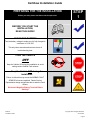
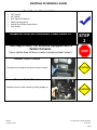
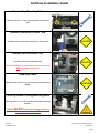
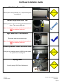
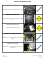
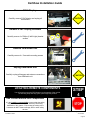
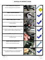
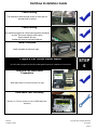
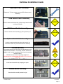
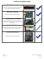
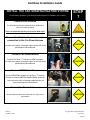
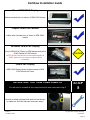
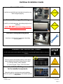
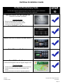
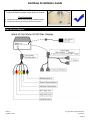
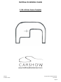
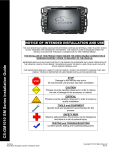
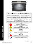
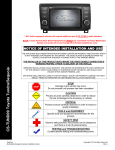
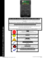
Installation Guide NOTICE OF INTENDED INSTALLATION AND USE THE AUXILIARY VIDEO DISPLAY IS DISABLED WHEN THE VEHICLE’S PARKING BRAKE IS NOT ENGAGED CS-FD1030 Ford F-150 installation Guide THE INSTALLER OF THIS PRODUCT MUST INSURE THE VIDEO DISABLE CONNECTION IS WORKING PROPERLY PRIOR TO DELIVERY OF THE VEHICLE. IMPROPER INSTALLATION COULD DISTRACT THE DRIVER OR INTERFERE WITH SAFE OPERATION OF THE VEHICLE, WHICH COULD RESULT IN SERIOUS INJURY OR DEATH, AND COULD ALSO VIOLATE STATE AND/OR FEDERAL LAW. CAR SHOW DISCLAIMS ANY LIABILITY FOR ANY BODILY INJURY OR PROPERTY DAMAGE THAT MAY RESULT FROM ANY IMPROPER OR UNINTENDED INSTALLATION AND/OR USE. STOP Damage to the vehicle may occur Do not proceed until process has been completed CAUTION CAUTION CarShow Multi-Media Navigation System Installation Guide Process must be carefully observed in order to reduce the risk of damage to the accessory or vehicle CRITICAL Process must be carefully observed in order to ensure a quality installation TOOLS and EQUIPMENT Specific tools and equipment recommended for this process SAFETY RISK Observe safe practices, this process can be dangerous and there is a risk of personal injury TESTING and TROUBLESHOOTING Content specific testing and troubleshooting points Copyright 2012 All Rights Reserved Rev A CarShow Installation Guide PREPARING FOR THE INSTALLATION Before you start, please read these critical steps below STEP 1 BEFORE YOU START THE INSTALLATION, READ THIS GUIDE! CHECK THE BATTERY Test the battery voltage to make sure it’s fully charged to a minimum of 12.8 VDC This only takes seconds and can save hours of troubleshooting later. TURN THE VEHICLE OFF Keep the Vehicle Off during the installation to avoid setting various Vehicle Fault sensors Keep the Vehicle OFF during the installation Failure to follow this may cause the AIRBAG FAULT SENSOR to become enabled. Dealer Service Departments charge a significant fee to reset the Fault Sensor. Disconnect Negative Battery Terminal Before Starting!! CarShow Installation Guide Copyright 2012 All Rights Reserved CS-FD1034 Page 2 CarShow Installation Guide Tools Required For Installation: T30 Torx Bit 3/8” Drill Bit 9/16” Open End Wrench Panel pry/removal tool Various size Phillips screw drivers 7mm Socket REMOVE CENTER CONSOLE COMPONENTS STEP 2 This step is ONLY for vehicles equipped with a Center Console. If your vehicle does not have a center console proceed to step 3 Remove Center Console Carefully remove dash trim at front of center console CAUTION Remove Center Console Carefully remove center console by pulling straight up CarShow Installation Guide CAUTION Copyright 2012 All Rights Reserved CS-FD1034 Page 3 CarShow Installation Guide REMOVE THE FACTORY RADIO You will need to remove multiple interior trim components prior to removing the factory radio. The following steps will help guide you through this process. STEP 3 Remove Top Dash Tray Cover Carefully remove rubber dash tray cover at top of dash CAUTION Dash Tray Cover Removed Dash tray cover removed at right Remove Dash Tray Bolts Carefully remove plastic dash tray 2x 7mm bolts (1 left/ 1 right) Remove Dash Tray Carefully remove dash tray with pry tool CAUTION Lift Rubber At Top Of Radio Left this to expose 2 x 7mm radio mounting bolts CarShow Installation Guide CAUTION Copyright 2012 All Rights Reserved CS-FD1034 Page 4 CarShow Installation Guide Remove Top Mounting Bolts Carefully remove 2 x 7mm mounting bolts as shown at right Remove Instrument Cluster Trim Carefully remove instrument cluster trim with pry tool CAUTION Remove Left Side Dash Trim Carefully remove left side dash trim CAUTION Note: On vehicles with center consoles these panels will NOT be completely removed. Drop Glove Box Carefully drop glove box to gain access to bolts securing airbag. CAUTION Carefully Remove Airbag Mounting Bolts Carefully remove 3 x 5/16 bolts that hold airbag mounting bracket. **NOTE: DO NOT disconnect airbag harnesses under any circumstances!!!** CarShow Installation Guide Copyright 2012 All Rights Reserved CS-FD1034 Page 5 CarShow Installation Guide Slide Airbag Towards You Carefully slide airbag towards you to expose dash panel mounting bolt CAUTION Remove Right Side Dash Trim Carefully remove 7mm bolt holding right side dash trim in place. Then remove dash trim. Note: On vehicles with center consoles these panels will NOT be completely removed. Right Side Dash Trim Removed Right side dash trim removed at right Note: On vehicles with center consoles these panels will NOT be completely removed. Carefully Remove USB/3.5mm AUX Panel Using pry tool, carefully remove USB/3.5mm Aux panel To expose 7mm mounting bolt CAUTION Unplug Panel Carefully unplug USB/3.5mm Media panel CarShow Installation Guide CAUTION Copyright 2012 All Rights Reserved CS-FD1034 Page 6 CarShow Installation Guide Remove 7mm Bolt After Media panel has been unplugged, remove 7mm bolt Remove OEM Radio Panel Carefully remove OEM radio panel by pulling out towards you CAUTION Unplug OEM Radio Panel Carefully unplug OEM radio harnesses CAUTION Remove SYNC Display trim Bezel Carefully remove 4 x 7mm bolts holding in SYNC display housing Remove SYNC Display Carefully remove 4 x 7mm bolts (2 left/2 right) holding in SYNC display CarShow Installation Guide Copyright 2012 All Rights Reserved CS-FD1034 Page 7 CarShow Installation Guide Remove SYNC Display Carefully remove SYNC display and unplug all connections CAUTION Remove SYNC Display Brackets Carefully remove 4 x Phillips (2 left/2 right) bracket screws Remove OEM Radio Unit Carefully remove 4 x 7mm radio mounting screws Unplug OEM Radio Unit Carefully unplug all harness and antenna connections from OEM radio unit LOCATING REMOTE COMPONENTS You will need to mount the GPS Antenna on the exterior of the vehicle. The following steps will help guide you through this process. CAUTION STEP 4 Use Caution around SRS Components It is the installer’s responsibility to ensure that the safety equipment in the vehicle is NOT adversely affected by installation of this system. Ensure that the routing of the harnesses do NOT obstruct airbags, SRS or other safety devices. CarShow Installation Guide Copyright 2012 All Rights Reserved CS-FD1034 Page 8 CarShow Installation Guide Mount the GPS antenna in a location on the exterior of the Vehicle Route the GPS harness away from other power harnesses in the vehicle. This will help to ensure optimum performance of the GPS system. Backup Camera Installation The following steps will instruct you how to install included backup camera STEP 5 OEM Lift Gate Handle T Tailgate Cutout Template Use template on page 20 to attach to lift gate handle as shown at right T Remove Lift Gate Panel Remove inner lift gate panel using T30 torx bit. **Check inside of lift gate PRIOR to drilling mounting hole for camera** T Mark Drilling Location Mark lift gate for drilling location using pick tool or flat blade screw driver CarShow Installation Guide Copyright 2012 All Rights Reserved CS-FD1034 Page 9 CarShow Installation Guide T Drill Camera Mounting Hole Drill 3/8” mounting hole in lift gate handle CAUTION T Attach Camera Adhesive Attach foam camera adhesive to back of camera T Insert Camera Into Lift Gate Carefully insert camera into lift gate and be sure camera is aligned properly Align Camera Once camera is aligned properly, apply pressure so that adhesive adheres properly to tailgate handle Install Mounting Hardware Put included locking washer and nut onto camera cable as shown at right Tighten Mounting Hardware Use 9/16 open end wrench to tighten Connect Cables Connect cables and be sure to put electrical tape on connections to ensure secure connection CarShow Installation Guide Copyright 2012 All Rights Reserved CS-FD1034 Page 10 CarShow Installation Guide Ro Cable Routing Fish extension cable through center of truck and run towards front of vehicle Ro Cable Routing Run cable through driver’s floor board grommet as shown at right. Then route cable to radio cavity. Some vehicles will vary. Installer will need to use best judgment. Install Complete Install complete as shown at right all Prepare Car Show Radio Bezel You will need to prepare the Car Show Navigation System for installation in the vehicle STEP 6 OE OEM and Car Show Bezel Preparation OEM Radio Bezel on left and Car Show on right OE OEM Radio Face Assembly Remove 7x T10 torx screws to remove OEM Radio face Assembly CarShow Installation Guide Copyright 2012 All Rights Reserved CS-FD1034 Page 11 CarShow Installation Guide OE OEM Radio Face Assembly Remove 4x T15 torx screws to remove OEM climate control Assembly OE OEM Hazard Switch Assembly Remove hazard switch assembly by depressing backside tabs on left and ride side CAUTION OEM Hazard Switch Assembly Remove hazard switch assembly by pulling assembly out CAUTION Optional Info Switch Assembly If vehicle is equipped with this optional Info switch, it is removed the same way as the hazard switch assembly. Included Buttons The included buttons need to replace the OEM buttons on the OEM switch assemblies. “Info, Setup, & Reset” buttons will only be used if vehicle is equipped with Info switch assembly mentioned above. OEM buttons are removed by pulling straight out. OEM buttons are a different size and will NOT fit in Car Show radio bezel CAUTION Install Switch Assemblies Install switch assemblies by snapping into place. CAUTION Hazard Switch Assembly Hazard switch assembly installed at right CarShow Installation Guide Copyright 2012 All Rights Reserved CS-FD1034 Page 12 CarShow Installation Guide Blank Switch Assembly If vehicle is not equipped with Info switch assembly then use included “blank” switch assembly shown at right. Blank Switch Assembly Blank switch assembly being installed at right OE Car Show Radio Face Assembly Re-install OEM climate controls to Car Show radio face assembly using 4x T15 OEM torx screws that were removed in previous step. Car Show Radio Face Re-install OEM radio face into Car Show radio face assembly using 7x T10 OEM torx screws that were removed. Car Show Radio Assembly Completed Car Show radio assembly at right CarShow Installation Guide Copyright 2012 All Rights Reserved CS-FD1034 Page 13 CarShow Installation Guide INSTALL THE CAR SHOW NAVIGATION SYSTEM You will need to prepare the Car Show Navigation System for installation in the vehicle. STEP 7 Connect GPS Antenna The GPS Harness must be tightened with a WRENCH to ensure it is properly seated. Failure to follow this step may result in poor GPS signal See the Harness Diagrams for more information Prepare the Vehicle side harnesses for connection to the Car Show Harness Use care not to pinch or damage cables as this will cause performance issues/failures CAUTION Connect Car Show Harness Connect Car Show “T” harness to OEM harnesses. Use care not to pinch or damage cables as this will cause performance issues/failures CAUTION Connect OEM Radio Chassis Connect OEM Radio chassis to Car Show “T” harness. Be sure to connect AM/FM & Satellite Radio antennas. Use care not to pinch or damage cables as this will cause performance issues/failures CAUTION Connect the Power Harnesses Be sure harness has secure connection to ensure proper performance CarShow Installation Guide CAUTION Copyright 2012 All Rights Reserved CS-FD1034 Page 14 CarShow Installation Guide Install Car Show Nav Monitor Carefully install Car Show Nav display ensuring that ALL connections are secure CAUTION Install Car Show Nav Monitor Carefully install Car Show Nav display ensuring that ALL connections are secure. Mount OEM Radio Chassis Into Dash Insert OEM Radio Chassis into dash and re-install radio mounting screws that were removed in step 2 Radio Face Assembly Connect radio Face/climate control assembly harnesses. Be sure all connectors are securely connected. CAUTION Snap Radio Face Assembly Into Place Carefully snap radio face assembly into place. Then, with the connectors Fully Engaged, turn the vehicle on and verify system powers up. CarShow Installation Guide Copyright 2012 All Rights Reserved CS-FD1034 Page 15 CarShow Installation Guide Mount OEM SYNC Display Adhere included Velcro to bottom of OEM SYNC display Prepare OEM SYNC Module Adhere other included piece of Velcro to OEM SYNC module Re-install OEM SYNC Display Connect OEM SYNC Display to OEM harness and Velcro SYNC Display to SYNC Module NOTE: Be sure the harness is connected properly as SYNC system will not function properly unless connected. CAUTION OEM SYNC Display OEM SYNC Display shown at right mounted to OEM SYNC Module via Velcro RE-INSTALL THE TRIM COMPONENTS You will need to reinstall all trim components that were removed in step 2 STEP 8 Re-Install Dash Trim Carefully re-install right hand side dash trim and be sure to replace the 7mm bolt that was removed in step 2. CarShow Installation Guide Copyright 2012 All Rights Reserved CS-FD1034 Page 16 CarShow Installation Guide Re-Install Dash Trim Carefully re-install left hand side dash trim and be sure that it’s aligned properly CAUTION Re-Install Passenger Side Airbag Carefully re-install passenger side airbag and glove box assembly CAUTION **NOTE: DO NOT disconnect airbag harnesses under any circumstances!!!** Re-Install Airbag Mounting Bolts Carefully re-install 3x 5/16 passenger side airbag mounting bolts ENABLE INSTALLER SETTINGS You will need to select certain Installer Setting based on any Optional Equipment that you may have installed STEP 9 Launch the Installer Setting Screen From any screen with the Menu Button, follow these steps to display the Installer Setting Screen, select: 1) From any Screen, select “Settings” 2) Press “Keypad,” Press “7253” and “Enter” Select the individual Settings as needed for the installed components Selectable options vary by product and installation. Select the options as applicable for the installed optional components. CarShow Installation Guide Copyright 2012 All Rights Reserved CS-FD1034 Page 17 CarShow Installation Guide Perform Pre-Delivery Tests You will need to perform several Pre-Delivery Tests to ensure customer satisfaction Some optional equipment may not be applicable STEP 10 Turn the vehicle ON and System ON Confirm the unit starts up properly Troubleshooting 1) Reset the System while the Vehicle is ON 2) Confirm all connectors are properly installed 3) Check the Vehicle and System Fuses Select RADIO as the Source Select SATELLITE RADIO as the Source Select Phone as the Source Select NAV as the Source Confirm the Navigation loads and signal strength is OK Troubleshooting 1) Confirm the antenna has an unobstructed view of the sky 2) Confirm the antenna is located on the outside of the vehicle 3) Confirm the antenna connection is properly tightened CarShow Installation Guide Copyright 2012 All Rights Reserved CS-FD1034 Page 18 CarShow Installation Guide Select Reverse Camera Confirm the backup camera screen shows in reverse Troubleshooting 1) Confirm the Camera is set to ON in the Installer Settings 2) Confirm the Camera is receiving 12VDC as required Main Harness Diagram CarShow Installation Guide Copyright 2012 All Rights Reserved CS-FD1034 Page 19 CarShow Installation Guide F-150 Lift Gate Camera Template Option Harness Diagram www.CarShowEntertainment.com CarShow Installation Guide Copyright 2012 All Rights Reserved CS-FD1034 Page 20