1
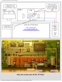
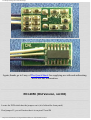
The Defpom Ranger RCI 2950 Mods Page
Ranger RCI 2950 modifications for the older (non DX) and
newer models (DX)
RCI-2950 DX (Second Generation)
www.r6-ru4montesecchieta.it
IZ5CCV
I was sent this e-mail from a visitor to my site, enjoy.
I have news on the RCI 2950 dx. The way you convert the channels is that there is a jumper in the
bag with the mic clip, you add that jumper to the block behind the face plate, put it on the pins on the
right hand side, only one jumper and you will get 24.000-32.000 !
There is nothing to clip in this radio for mod. just turn up the one on the inside that says modulation.
Everything is marked on the inside by name, am power, SSB power, and any other power. If tuned
right it will key 3 watts and swing to 35 watts, thank you Joe L.
The EPT695010z board can be modified in the way described.
RCI-2950 DX (First and Second Generation)
The radios with the board number EPT695011Z, which some people say aren't able to be modified
can be, but only with a frequency expansion module. (see First Generation DX)
The only place I have found offering them is Panther Electronics and The Quack Shack
Using this module and the jumper in the way described will result in Frequency coverage from
21.000MHZ to the top of the 10 meter band.
Without the jumper, the radio will cover 24-32MHz.
Thanks to Matt for sending me this info !
How to get down to 21.000MHz with the above module installed
The radio must have the module connected to RX/TX from 32.000 - 24.000 MHz.
http://www.radiomods.co.nz/ranger2950mods.html (1 di 10)12/09/2009 22:45:57
The Defpom Ranger RCI 2950 Mods Page
Open radio on the speaker side.
Face the back of the radio towards you so the front panel is away from you.
Looking where the module is plugged in on the back side of the front panel there will be 2 sets of
pins right above the module plug in.
Connect the 2 right pins together.
Reassemble the radio and turn radio on.
The radio should start at 21.000MHz.
Here is probably the best explaination I have had about the different versions of the 2950, make sure
you read it !!
This was sent to me by Larry, from The Quack Shack
I have attached a word document that explains the modification for this radio. I hope this helps you
one day, I spent much time figuring this out and creating this mod to be easy to understand for
anyone.
The weak solderer should not attempt this as they could smoke the CPU if not VERY careful.
Also, you need to change what you are calling each type of RCI,there are NO old 2950DX models.
(I'm pretty sure).
There are old RCI's with the red displays, (three generations of these to be exact).
Version 1 has the onboard battery for the memory and has to switch from CB band to frequencies by
using the LOCK button.
The second generation unit will have the battery eliminated, and still has the large capacitor right in
the way of the bracket knob mounting hole on the right side, problem there is someone gets
aftermarket knobs and they are too long and bend the cap over till it shorts out or breaks the solder
loose on the board. This radio is also where they began using the MAN button to change from CB
mode to frequency mode.
The third generation they fixed a few of the interior flaws, such as the large capacitor problem.
Then the modifiable 2950dx, and the "Blue Dot" 2950dx which is the non modifiable version.
http://www.radiomods.co.nz/ranger2950mods.html (2 di 10)12/09/2009 22:45:57
The Defpom Ranger RCI 2950 Mods Page
Easiest way of identification on these is the green display and they actually say 2950DX right on
them.
The DX is also modifiable to seven megs, play around with the jumper settings, you will be amazed
what this radio appears to be able to do. I have yet to put a 40 meter capable antenna on this unit to
see if it actually works there or not, I do know that it keys there and seems to pick up static there too.
Have a good day and hear from you later.
Larry
---------------------------------------------------Here is the Mod Info Larry sent me, remember what he said,it is not for the poor solderer, unless you
want ot ruin your radio.
RCI 2900 DX Series (Blue Dot Version) , First Generation DX
Modification of “blue dot” unit is possible with “E-Chip” sold separately. Unfortunately, colorcoding is not possible, as these chips never seem to come with the same color wires on them, so I
have given them numbers instead. These instructions are in the simplest of laymen's terms
possible so anyone can do them with a steady hand and a good soldering iron.
1.
2.
3.
4.
5.
6.
7.
8.
9.
10.
11.
12.
Turn off power and remove power leads
Remove top and bottom covers, knobs, and faceplate
Remove the 4 screws holding the CPU board to the chassis
Flip radio over so solder side of main board is facing you and back of radio is toward you
Fold CPU board down carefully so it looks somewhat like Image 1
Now, on the right side of the CPU chip count up 5 legs from the bottom, you will know you
have the right one as there is no trace going to this leg
If “E-Chip” comes with wires and plug, remove plug and leave wires as long as possible, strip
1/8” of wire ends and tin. If “E-Chip” comes with plug only, unsolder plug and add 3 wires in
its place.
With solder side of “E-Chip” facing you as in Image 2 , connection #3 solders to the 5 th leg
previously identified in step 6 (This is the most dangerous part, be careful!)
Now, flip the radio over so you can see the same side of the CPU board, still from the back as
in Image 1 , but now it will be upside down
Solder connection #2 of the “E-Chip” to the negative side of the 220 capacitor as shown in
Image 1
Connection #1 on the “E-Chip” gets soldered in place as in Image 3
Put radio back together, hook up power, and turn it on. Unit is expanded to 24.0000 to
32.0000 mhz
Remove “Blue Dot” from back of radio!
http://www.radiomods.co.nz/ranger2950mods.html (3 di 10)12/09/2009 22:45:57
The Defpom Ranger RCI 2950 Mods Page
Here are some pics of the "E Chip"
http://www.radiomods.co.nz/ranger2950mods.html (4 di 10)12/09/2009 22:45:57
The Defpom Ranger RCI 2950 Mods Page
Again, thanks go to Larry of The Quack Shack for supplying me with and authorising
me to use this information.
RCI-2950 (Old Version, not DX)
Locate the PCB which has the jumpers on it (it is behind the front panel)
Find jumper J2, you will notice that it is on pins P3 and P4
http://www.radiomods.co.nz/ranger2950mods.html (5 di 10)12/09/2009 22:45:57
The Defpom Ranger RCI 2950 Mods Page
If you remove it you will have coverage from 26.000-29.700 MHz
If you place it on pins P1 and P2 you will have coverage from 26.000-32.000 MHz
Now reset the CPU by pressing the button below J2
To get a channel read out locate J1, the jumper will be on pins P1 and P2, move it to P2 and P3.
Now when you press the lock button you will toggle between CB channels and the VFO readout !
RCI-2950 (New Version, not DX)
On this version there is only one jumper which has two positions.
In one position it gives 28.000-30.000 MHz
In the other it gives 26.000-30.000 MHz
BUT if you short out all three pins you get 26.000-32.000 MHz !!
How to get LOWER than 21.000MHz ! (on DX versions)
Here is the procedure to cover 18-36MHz though the functional limits of the radio, usually from
20.000MHz to 30.000MHz (functional meaning TX with measurable wattage and on frequency).
You need the expansion module installed and the two pins jumpered to cover 21 to 29.699MHz (as
shown above), if your radio covers 24 to 32MHz this will work too but with a different range.
Next you manipulate the SPLIT feature.
We start with a reference frequency in CB mode...let's use CH 1 (26.965).
To get to 20.000MHz, program the split function by pressing [PROG] then [SPLIT], move the curser
with the [SHIFT] key and program in 6.965....Now press [ENTER], press [SPLIT] until you see "split" in the display.
http://www.radiomods.co.nz/ranger2950mods.html (6 di 10)12/09/2009 22:45:57
The Defpom Ranger RCI 2950 Mods Page
Next press [MAN] to get to the CB band mode and move to CH1...press the mic-key and you hear a
"buzz" from the radio (this step is neccesary).
Release the key and press the [MAN] button and BINGO!---you now have 20.000MHz in the display
(you might even hear WWV in Ft. Collins CO, there).
To transmit, just press [SPLIT] until the "split" is off of the display and you're good to go!
(Caveat: you can't move from the jumped-to frequency without defaulting to 21.000MHz and you
can't save the frequency to a memory).
Using this math trick, you can jump ANYWHERE from 18.6251MHz to 36.1049MHz (yes, you can
go up using the "+split" function).
Enjoy!............THE INSPECTOR
Important information BEFORE you buy a new 2970DX !!
Hello, and thanks for this site. I would like to offer some insight into the RCI-2970DX
UNMODIFYABLE Model. (this may be the "Blue Dot" version, as shown above)
There is two NEW types.
ONE is an EXPORT sold to dealers who offer it for sale, and the Second one is a Model sold to be
used as US for Ham Radio ONLY and this one is the unmodifyable one.
It doesn't have the pigtail for the module for 11 meters nor do the pins behind the front do anything to
make it go to the 11 meter band.
I know that many have bought this unit expecting to do the mod later and found out to late that this
radio would not go to 11 meters.
I was ONE that this happened to. I would hope that this could be cleared up and save a lot of time and
money if only the person buying this radio did his or her homework before buying the 2970DX.
Thanks again for this Site.
Harold Bates
http://www.radiomods.co.nz/ranger2950mods.html (7 di 10)12/09/2009 22:45:57
The Defpom Ranger RCI 2950 Mods Page
More mods sent to me by a visitor
TALKBACK AND AUTOSQUELCH IN THE RANGER WITHOUT DRILLING HOLES FOR
SWITCHES
Tired of having to drill holes in your Ranger for a new mod?
Try this.
The SWR and Roger Beep functions are open collector outputs pulled to ground by the CPU when
the specific function is activated.
There are a few more, such as NB and ANL (3 steps), and a voltage function from the Dimmer that
can also be used for various mods.
Keep in mind that the transistors are not power devices, if you wish to control some circuit needing a
larger current sink use a fire train, i.e., Another device which will handle the load.
For example, you can use the SWR or Roger Beep for talk back from the front panel by removing the
wire from the connector on the main board and simply soldering it to the cathode of D78.
Do not cut or remove D78, just connect the wire from the function used to the side opposite the band.
Do not connect to the banded side !
The green wire from CN607 to the main board plug is roger beep, right behind the mike plug 3
inches, a 6 pin connector; black (ground on one end, green (the RB signal control line we want) on
the other end.
If you use SWR function, go to plug from CN608, just behind antenna output, two coax wires with a
common ground.
The hot opposite the shield is the one you want to use for a transistor low, activated when SWR is lit
on the LCD display.
I use both functions because I also have auto squelch, that mod next.
Don't forget to open D115 to clean up the audio quality of your talk back.
Do not replace the zener D115 with a cap. or resistor or whatever like you have seen out there, just
leave it open.
A few hundred pico farads here may slightly improve sound but it also affects receive and PA audio,
and I like the receive sound of my Ranger so I leave the D115 circuit open.
If you love SSB like I do but also like the chicken radio talk back with connex, but hate the distorted
(lack of carrier for AM detection which is how TB works on Ranger and Galaxy radios) TB on SSB
and drilling holes in your new radio, you will love this idea.
Now for auto squelch.
Look at the 3 pin connector from the squelch control, up front just to the right of center.
Wires are violet, Gary, and white. Look on bottom, center pin is grounded.
Cut foil to un ground.
Look to unused pad just beside 3 pin Connector, you will see it goes to 22k to ground.
Jumper center pin to this point.
http://www.radiomods.co.nz/ranger2950mods.html (8 di 10)12/09/2009 22:45:57
The Defpom Ranger RCI 2950 Mods Page
Now at this point you will connect the wire (green) from the CPU board to roger beep (you removed
it from the 6 pin Connector to RB) to this junction of center pin to 22k to ground.
You now have auto squelch by activating the no longer functioning roger beep.
The problem is: with RB lit you have normal squelch, with RB out you have auto squelch. So, to
invert this like I did (I like things to be on with indicator not vice versa), connect the green wire to the
base of a 2N3904 transistor.
Connect the base to the 10k going to 8 volts.
Connect the emitter to ground, collector to the center pin on the 3 pin squelch pot. Connector.
Now you have auto squelch on when RB is lit, and talk back on (previous mod) when SWR is lit.
COOL!
You can make the auto squelch looser by lowering the value of the 22k R315, to make it tighter just
raise the squelch control when auto squelch is on. You can also play with R71 (47k in some and 39k
in others), but it is better just to alter R315 (22k) if need be.
For better AM receive change the detector diodes D34,35 to a better quality SK9975, or use ECG or
NTE 583 (germanium only here, no silicon).
While you can reduce the receiver sensitivity to help overload by changing R78 from 2.2k to 6.8k, I
don't think it is a good idea if you are into long distance communication.
For front end overload the going mod is to change R49 (100k) to 33k.
The problem here is it also severely degrades extreme weak signal reception. So to fix this just tap the
hot end of R49 (the other end is ground) with a 100k trimmer pot in series with a 1k (to protect the
quad op amp's output from damage if you turn the pot all the way down by accident) for a variable
trimmer adjustment for overload protection, set the pot for best effect (other end of your pot is
grounded to parallel the 100k R49).
Now for the cool part.
If you have no use for switch able talk back then use the signal described earlier (SWR or RB) for the
ground end of the trimmer pot (or fixed value if you go that way).
Now you can at the touch of the SWR or RB button control front end overload and restore weak DX
receive by pressing the button again. WAY COOL!
For power limit removal just solder the base of TR32 to ground, looking at the foil side you will see
the base lead is closest to the wall, next to a handy close point to ground.
For faster scan and function speeds replace X601 (a 4 MHz ceramic resonator) with an MHz crystal,
but remember speeding up the CPU makes it run hotter, and going to fast will make it prone to
locking up.
If the load capacitance of your crystal to too far off, the circuit may not oscillate, play with the values
for R630 (1M), and C612,613 (33pf).
For a little more power replace C270 (to base driver), C261,262 (base of finals) with 1000 pf, or just
parallel the 560 pf's there already with about 330 pf, re tune radio output stage for best power.
While changing the regulator transistor Q51 (2SB754) to a higher power unit such as a 2SB688
(never use the junk ECG 37) may seem a good idea, the collector to emitter"on" resistance is critical,
or the unit will overheat. So if you sub this part away from 2SB754 pay attention to this fact!
http://www.radiomods.co.nz/ranger2950mods.html (9 di 10)12/09/2009 22:45:57
The Defpom Ranger RCI 2950 Mods Page
For you 2970 owners another choice exists. Use the RB or SWR signal to turn the power amplifier on
and off.
Locate the 2 pin plug going to the linear unit. One wire is the hot 8 volts for transmit.
Connect this to the emitter of a PNP 2N3906, tie the emitter through 4.7k to the base.
Connect the base through 10k to your chosen open collector output either RB or SWR.
Connect the collector to the wire going to the linear.
Now when you push the front button you will allow or not allow the transmit 8 volts to activate the
relay inside the linear unit. More Cool!
No holes in the covers and selectable high or low power!
Russell Clift AB7IF
http://www.cybertrails.com/~drvel/
This counter shows the number of hits since the 7th March 1999
Go Back To The Modifications Page
Go Back To The Home Page
Go Back To The Main Home Page
Copyright © The Defpom 1997-2008
http://www.radiomods.co.nz/
http://www.radiomods.co.nz/ranger2950mods.html (10 di 10)12/09/2009 22:45:57