1
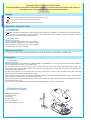
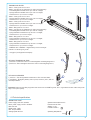
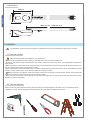
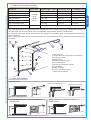
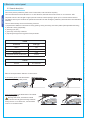
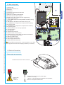
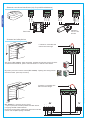
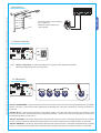
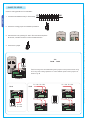
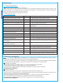
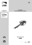
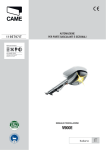
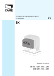
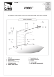
AUTOMATION FOR SECTIONAL AND OVERHEAD GARAGE DOORS VER SERIES INSTALLATION MANUAL V900E “IMPORTANT SAFETY INSTRUCTIONS FOR INSTALLATION” “CAUTION: IMPROPER INSTALLATION MAY CAUSE SERIOUS DAMAGE, FOLLOW ALL INSTALLATION INSTRUCTIONS CAREFULLY” “THIS MANUAL IS ONLY FOR PROFESSIONAL INSTALLERS OR QUALIFIED PERSONS” ENGLISH This symbol indicates sections to be read with particular care. This symbol indicates sections concernig safety. This symbol indicates notes to communicate to users. 2 Destination and limits of use 2.1 Intended use The V900E automated kit is designed to power sectional and overhead doors installed in condominiums and residential homes. The use of this product for purposes other than as described above and installation executed in a manner other than as instructed in this technical manual are prohibited. 2.2 Limits to use 24V (d.c.) gearmotor with lifting force of up to 500N for: - counterweighted overhead doors up to 2.40m in height; - spring-balanced overhead doors up to 3.25m in height; - sectional doors up to 3.20m in height. 3 Reference standards This product complies with the following standards: EN 12978, UNI EN 954-1, CEI EN 60335-1, UNI EN 12453. 4 Description 4.1 Automation V900E was designed and manufactured by CAME CANCELLI AUTOMATICI S.p.A. and is compliant with the safety regulations in force. Guaranteed 24 months if not tampered with. The automation is mainly made up of an engine block, a transmission rail – with either a belt or chain transmission system – and a transmission arm. Inside the ABS container which features a window for the courtesy light, we find: the 24V gearmotor, the control panel and the transformer. The gearmotor is made up of an aluminium die cast casing, which houses a worm-screw and helical-crown gear irreversible reduction system, lubricated by permanent fluid grease. The transmission guide is made of cold-pressed galvanised sheeting. At the front end there is belt/chain tension device; fastened to the other end is an ABS support to hold up the gear motor. Inside the transmission guide runs the traction slide which includes the emergency release mechanism and the bracket for fastening to the transmission arm. The transmission arm is available in several sizes and shapes depending on the type of garage door. 4.2 Description of the parts 1 GEARMOTOR SECTION 1) Protective cover 2) Gearmotor 3) Transformer 4) ZL56 circuit board 5) Standard transmission arm 5 2 3 4 2 The data and information reported in this installation manual are susceptible to change at any time and without obligation on CAME cancelli automatici s.p.a. to notify users. 1 Legend The data and information reported in this installation manual are susceptible to change at any time and without obligation on CAME cancelli automatici s.p.a. to notify users. ENGLISH TRANSMISSION GUIDES V0679 – Chain guide unit L=3.02 m V0684 – the same as the V0679 but two parts need assembling - counterweighted overhead doors up to 2.40 m in height; - Spring balanced overhead doors up to 2.25 m in height; - sectional doors* up to 2.20 m in height. V0682 – Chain guide unit L=3.52 m - Spring balanced overhead doors up to 2,75 m in height; - sectional doors* up to 2.70 m in height. V0683 – Chain guide unit L=4.02 m - Spring balanced overhead doors up to 3.25 m in height; - sectional doors* up to 3.20 m in height. V0685 – Belt guide unit L=3.02 m V0687 – the same as the V0685 but two parts need assembling - counterweighted overhead doors up to 2.40 m in height; - spring balanced overhead doors up to 2.25 m in height; - sectional doors* up to 2.20 in height. V0686 – Belt guide unit L=3.52 m - spring balanced overhead doors up to 2.75 m in height; - sectional doors* up to 2.70 m in height. V0688 – Belt guide unit L=4.02 m - spring balanced overhead doors up to 3.25 m in height; - sectional doors* up to 3.20 m in height. 119RIE024 and 119RIE088 – Supplementary tension and angle brackets for fastening the guides * see page 5 (5.4 Applicative examples). OPTIONAL TRANSMISSION ARMS 1) 001V201- Transmission arm for counterweighted overhead garage doors. 2) 001V122 – Extra-strength transmission arm for sectional garage doors; OPTIONAL ACCESSORIES 1) 001V121 – Pull-string release mechanism to affix onto the handle; 2) 001V0670 – Emergency battery start-up card, houses 2 (12V-1,2Ah not included) batteries ; 1 2 1 2 Important! Check that the safety equipment and accessories are CAME originals; this is a guarantee that also makes the system easy to set up and upkeep. 4.3 Technical specifications GEARMOTOR V900E Power supply: 230V A.C. 50/60Hz Motor power supply: 24V D.C. 50/60Hz Max draw: 6A Rated power: 130W Max. torque: 500Nm Average speed: 6m/min Operative intermittence: 50 % Protection level: IP40 Weight: 5,7 kg Insulation class: II # Operating temperature: # 3 4.4 Dimensions MM MMMIN¿MMMAX 5 Installation The installation must be carried out by export, qualified personnel in total compliance with the norms in effect. 5.1 Preliminary checks Before proceeding with the installation, it is necessary to: • Make sure the area selected for the mounting of the base and for the unit itself is hazard free; • Provide for a suitable omnipolar disconnection device with contacts more than 3 mm apart, and independent (sectioned off) power supply; • Make sure that any connections inside the case (that provide continuance to the protective circuit) be fitted with extra insulation as compared to the other conductive parts inside; • Make sure that the point where the gearmotor is fastened is protected from impact and that it is sturdy. The fastening must be carried out using screws and/or rivets that are suitable for the type of surface; • Make sure that any connections inside the container (made for the continuity of the protection system) are provided with additional insulation compared to the other conductive parts inside; • Make sure that the door has a sturdy enough structure, that the hinges be in proper working order and that there is friction between moving and fixed parts; 5.2 Tools and materials Make sure all tools and materials necessary are within reach to install the edge in total safety, and in compliance with the regulations in force. The following figure illustrates the minimum equipment needed by the installer. 4 The data and information reported in this installation manual are susceptible to change at any time and without obligation on CAME cancelli automatici s.p.a. to notify users. ENGLISH MM MM 5.3 Cable list and minimum thickness Connections Type of cable Length of cable 1 < 10 m L. of cable 10 < 20 m L. of cable 20 < 30 m 230V power supply FROR CEI 20-22 CEI EN 50267-2-1 Photocell transmitters Photocell receivers 24V power supply to accessories Control and safety devices Antenna connection 3G x 2,5 mm2 3G x 4 mm2 2 x 0,5 mm2 2 x 1 mm2 2 x 1,5 mm2 2 x 0,5 mm2 2 x 0.5 mm2 2 x 0,5 mm2 4 x 0,5 mm2 4 x 0,5 mm2 4 x 0,5 mm2 2 x 0,5 mm2 2 x 0,5 mm2 2 x 1 mm2 2 x 0,5 mm2 2 x 0,5 mm2 2 x 0,5 mm2 RG58 ENGLISH max. 10 m N.B.: if the cable length differs from that specified in the table, then you must determine the proper cable diameter in the basis of the actual power draw by the connected devices and depending on the standards specified in CEI EN 60204-1. For connections that require several, sequential loads, the sizes given on the table must be re-evaluated based on actual power draw and distances. When connecting products other than those mentioned in this manual please see the documents provided with the products themselves. 7 8 1 3 2 4 5 1) Gearmotor unit 2) Incorporated control panel with radio transmitter 3) Transmission guide 4) Release device 5) Standard transmission arm 6) Key-switch selector 7) Flashing light movement indicator 8) Tuned antenna 9) Safety photocells 10) Indoor push button control 11) Safety sensitive profile 10 6 9 48 9 28 11 5.4 Applicative examples SECTIONAL DOOR ( SPRING BALANCED FULLY RETRACTABLE SWING OUT OVERHEAD DOOR COUNTERWEIGHTED PARTIALLY RETRACTABLE SWING OUT OVERHEAD DOOR ( * single-guide sectional door H - 100mm * double-guide sectional door H The data and information reported in this installation manual are susceptible to change at any time and without obligation on CAME cancelli automatici s.p.a. to notify users. Flashing lamp 3G x 1,5 mm2 ( 5 5.5 Preparing the transmission guide ENGLISH 1) Fasten the bracket to the tension device on the transmission guide using the supplied bolts and washers. M6 M6 x 20 ¿MM ¿MM 2) Position the transmission guide in the following manner: - for sectional doors directly above spring-release coiling shaft (between 20 and 30 mm of the shaft’s axis). N.B.: if the distance between the coiling shaft and the top part of the door is between 300 and 600 mm, use the V122 arm (see technical documentation attached); V122 (MMMAX ¿MM - for overhead doors between 10 and 20 mm from the highest sliding point of the door. N.B.: for pratially-retractable swing out counterweighted garage doors, use the V201 arm (see technical documentation attached). V201 6 The data and information reported in this installation manual are susceptible to change at any time and without obligation on CAME cancelli automatici s.p.a. to notify users. The following applications are only examples, as the space required for unit installation and the accessories vary depending on dimensions and therefore it is up to the installer to select the best solution. 5.6 Fastening the transmission guide ENGLISH The data and information reported in this installation manual are susceptible to change at any time and without obligation on CAME cancelli automatici s.p.a. to notify users. 1) Fasten the transmission guide to the centre of the doorway using the proper screws. Raise the guide until it is horizontal with the ceiling so as to choose the proper type of fastener. 2) If the angle brackets are not sufficient, cut the tension brackets down to the right length and fasten them to the ceiling. N.B.: to strengthen the bar additional angle or tension brackets may be installed. M6 M6 x 14 3) Fasten the transmission guide to the ceiling using the proper bolts. 7 5.7 Fastening the guide arm to the transmission guide 2) Release the traction slide by turning the small level clockwise. Move the slide towards the door and hook it onto the guide arm with the supplied bolt. UNI 5739 M6 x 20 8 The data and information reported in this installation manual are susceptible to change at any time and without obligation on CAME cancelli automatici s.p.a. to notify users. ENGLISH 1) Fasten the guide arm to the top of the door frame, perpendicularly to the transmission guide. Use the supplied rivets and other suitable bolts and screws. 5.8 Fastening the gearmotor to the transmission guide ENGLISH The data and information reported in this installation manual are susceptible to change at any time and without obligation on CAME cancelli automatici s.p.a. to notify users. 1) Remove the cover of the motor unit. UNI 6954 ø 3.9 x 13 2) Fasten the motor unit to guide’s support racket using the three screws supplied with the kit. N.B.: if needed, the unit may be fasten in the other three perpendicular positions, as per the drawings. UNI 6955 ø 6.3 x 45 3) Affix the cable gland in the hole used to convey the electrical cables. 9 6 Electronic control panel The control panel is powered by 230V on the L-N terminals, with a 50/60 Hz frequency. The command devices and accessories run on 24V. Moreover, the total accessories cannot run on more than 40W. The panel controls a service light to light up the service area; at each opening it lights up for 2 minutes and 30 seconds. The V0670 card may be connected to operate the automation kit with emergency batteries (see the technical documentation attached). The card automatically controls the following functions: 1) amperometric detection of obstructions during opening, closing and during slow down phases (with adjustable sensitivity); 2) automatic closing (adjustable); 3) working cycle (80”); 4) open-stop-close-stop command 5) reopening dueing the closing phase of the photocells. FUSES Protection Fuse type Motor 7,5A Circuit board (line) 1,6A Accessories 3,15A Command devices (control unit) 315mA LIGHTS Service E17 24V 25W Detail of the amperometric detection of obstructions: in the opening phase: invert the direction of movement until completely closed; in the closing phase: invert the direction of movement until completely opened; Warning! After three, consecutive inverted cycles, the door will stay open excluding automatic closing function: to close the door, use the remote control or a command button. 10 The data and information reported in this installation manual are susceptible to change at any time and without obligation on CAME cancelli automatici s.p.a. to notify users. ENGLISH 6.1 General description Warning! Before doing any work on the automation kit, cut off the pwer supplì and disconnect the emergency batteries (if connected). 2 3 4 6 6 19 18 #"/!2$&53%M!& 1) Line fuse 1.6A 2) Emergency batteries’ slot 3) Gearmotor 4) Transformer 5) Transformer connection terminal board 6) Motor fuse 7.5A 7) Gearmotor connection terminal board 8) Encoder connection terminal board 9) Signal Led for radio-code and encoder programming 10) Radio-code save button 11) SLOW. SENS: adjustment of amperometric sensitivity during closing phase 12) TCA Trimmer: adjustment of automatic closing cycle 13) CL. SENS Trimmer: adjustment of amperometric sensitivity during closing phase 14) OP. SENS Trimmer: adjustment of amperometric sensitivity during opening phase 15) Command buttons for end-stop adjustment 16) Function selector 17) Courtesy light 18) Accessories’ fuse 3,15A 19) Central control unit fuse 315mA 20) Accessories’ and control device connection terminal board 21) “AF” radiofrequency board socket 22) Electrical cable sockets 23) Led indicator for power-on 24) Power supply terminal board 25) Radio antenna terminal board ENGLISH The data and information reported in this installation manual are susceptible to change at any time and without obligation on CAME cancelli automatici s.p.a. to notify users. 6.2 Main components 11 12 13 14 3,/73%.3 !#4 #,3%.3 /03%.3 15 /0%. /0#, 10 %.#2!$)/ /. !##&53%!& 66 6 5 - . % 7 8 16 9 :, ,).%&53% !& 23 -/4/2&53% !& ,4 ,4 , 17 . 24 1 !& 6 21 20 25 22 6.3 Electrical Connections Power supply and accessories Buttonhole terminal for earth connection. , . Power supply 230V a.c. – 50/60 Hz + - Teminal board for accessories’ power supply: - at 24V a.c. normally; - at24V d.c. when the emergency batteries are in operation; Maximum total power allowed: 40W. 11 % 6 6 Gearmotor 24V d.c. with encoder Transformer Command and safety devices If a button is connected, then remove the fuse-bridge. % # Stop button (N.C. contact) - Stops movement, excludes the automatic closing functions. To restart the automated kit, press a command button or a remote control button. Key and/or push button selector switch (N.O. contact) - Opening and closing devices. Command modes: open-stop-close-stop If a button is connected, then remove the fuse-bridge. % # 48 28 N.C. Contact for “reopening during closing” - Input for photocells, sensitive profiles and other devices complying with EN 12978 standards. During the closing phase, operating the device will invert the motion until complete opening is achieved. 12 RX 48 # .# TX 48 The data and information reported in this installation manual are susceptible to change at any time and without obligation on CAME cancelli automatici s.p.a. to notify users. RED GREEN . BROWN - WHITE GREEN RED BLACK BROWN BROWN ENGLISH ,4 ,4 WHITE Gearmotor, encoder and transformer (only for possibile maintenance) Warning devices % # ENGLISH Movement Flasher (contact capacity: 24V – 25W max.) Flashes during the opening and closing phases. #"/!2$&53%M!& 6.4 Function selection 3,/73%.3 #,3%.3 !#4 /03%.3 /0#, /0%. %.#2!$)/ /. !##&53%!& 66 6 - . % /. ON :, ,).%&53% !& -/4/2&53% !& ,4 ,4 , !& OFF . 1 ON – Encoder programming - activates the opening and closing end-stops adjustment procedure. 2 deactivated. Keep the dip-switch in OFF position #"/!2$&53%M!& 6.5 Adjustments 3,/73%.3 !#4 #,3%.3 /03%.3 /0#, /0%. %.#2!$)/ /. 66 6 - . % 3,/73%.3 :, ,).%&53% !& ,4 ,4 , -/4/2&53% !& !& !#4 #,3%.3 /03%.3 !##&53%!& The data and information reported in this installation manual are susceptible to change at any time and without obligation on CAME cancelli automatici s.p.a. to notify users. . Trimmer SLOW.SENS. = Adjusts the amperometric sensitivity that controls the force of the engine developed during different phases, slow-down; if said force becomes greater than the adjusted level, the system intervenes by inverting the direction of movement. Trimmer A.C.T. = Adjusts the waiting time in the opening position. Once this time frame has lapsed, an automatic closing procedure is performed. The waiting time may be adjusted to between 1 second and 120 seconds. Adjusting to the minimum excludes the automatic closing function. Trimmer CL.SENS. = Adjusts the amperometric sensitivity that controls the force of the engine developed during movement closing; if said force becomes greater than the adjusted level, the system intervenes by inverting the direction of movement. Trimmer OP.SENS. = Adjusts the amperometric sensitivity that controls the force of the engine developed during movement opening; if said force becomes greater than the adjusted level, the system intervenes by inverting the direction of movement. 13 7 Programming the end-stops IMPORTANT: before performing any programming, read the instructions carefully. Carry out the following instructions in the proper order otherwise the programming will fail. ENGLISH - Release the automation and position the door in the fully opened position. - When the door is fully opened, fasten the mechanical stop to the traction slide. Mechancal stop Slide guide - Manually close the door until the release is locked into place again. Programming the end-stop in the closing phase - Position dip-switch n°1 to ON (the programming signal led flashes). Push and keep pressed the AP/CH switch until the door closes... 3,/73%.3 !#4 #,3%.3 /03%.3 /0#, /0%. %.#2!$)/ 3,/73%.3 - . % - . !& 14 !#4 #,3%.3 /03%.3 /0#, /0%. %.#2!$)/ /. /. % !& The data and information reported in this installation manual are susceptible to change at any time and without obligation on CAME cancelli automatici s.p.a. to notify users. Preliminary operations ...then briefly press the ENC/RADIO button (if the signal led stays on for some seconds and then starts flashing again, the programming operation is satisfactorily complete). 3,/73%.3 !#4 #,3%.3 /03%.3 /0#, %.#2!$)/ /0%. 3,/73%.3 66 6 - . % !##&53%!& /03%.3 /0#, /0%. %.#2!$)/ 66 6 - . % :, :, ,).%&53% !& #,3%.3 ,).%&53% !& -/4/2&53% !& ENGLISH The data and information reported in this installation manual are susceptible to change at any time and without obligation on CAME cancelli automatici s.p.a. to notify users. !##&53%!& !#4 /. /. -/4/2&53% !& !& !& Programming the end-stop in the opening phase - Push and keep pressed the OPEN button until the door is fully open... 3,/73%.3 !#4 #,3%.3 /03%.3 /0#, /0%. %.#2!$)/ /. !##&53%!& 66 6 - . % :, %&53% !& -/4/2&53% !& !& ...then briefly press the ENC/RADIO button (if the signal led stay on the programming operations is satisfactorily complete). Finally, set dip switch n°1 back to OFF. 3,/73%.3 !#4 #,3%.3 /03%.3 /0#, /0%. %.#2!$)/ 3,/73%.3 !##&53%!& 66 6 - . % !##&53%!& #,3%.3 /03%.3 /0#, /0%. %.#2!$)/ 66 6 - . % :, :, .%&53% !& !#4 /. /. .%&53% !& -/4/2&53% !& -/4/2&53% !& !& !& TEST Use the AP/CH button to command both an opening and a closing to verify whether the programmino was successful. 15 8 Activating the remote control Radiofrequecy card Only for highlighted cards. Position the jumper as show in the illustration depending on the series of transmitters used (see figure). TOP Frequency/MHz Radiofrequency card Series of transmitters FM 26.995 AF130 TFM FM 30.900 AF150 TFM AM 26.995 AF26 TOP AM 30.900 AF30 TOP AM 433.92 AF43S / AF43SM TAM / TOP AM 433.92 AF43SR ATOMO AM 40.685 AF40 TOUCH TAM Connect the radiofrequency card to the electrical board AFTER SHUTTING OFF THE POWER (or disconnecting the batteries). N.B.: The circuit board recognizes the readiofrequency card only when it is running in electrical power. 3,/73%.3 !#4 #,3%.3 /03%.3 /0#, /0%. %.#2!$)/ /. !##&53%!& 66 6 - . % Radiofrequency card :, ,).%&53% !& ,4 ,4 , Electrical board 16 -/4/2&53% !& !& . The data and information reported in this installation manual are susceptible to change at any time and without obligation on CAME cancelli automatici s.p.a. to notify users. Connect the antenna with the RG58 cable to the apposite terminals on the board. #"/!2$&53%M!& ENGLISH Antenna Transmitters TOP T432M - T312M D 0 ENGLISH The data and information reported in this installation manual are susceptible to change at any time and without obligation on CAME cancelli automatici s.p.a. to notify users. TOP SERIES 0 Input the code into the C selector and set the channel on D (P1 = CH1 and P2 = CH2: default setting) P1 /. CH1 0 0 0 CH2 CH4 /. /. CH3 CH4 TOP T432S - T432SA - T434MA - T432NA - T434NA TOP T434M - T314M 0 CH3 /. /. CH2 /. P2 /. CH1 C /. Input only the code See instructions attached P1 = CH1 P2 = CH2 P3 = CH3 P4 = CH4 E CAM C TFM T132 - T134 - T138 T152 - T154 - T158 TAM T432 - T434 - T438 - TAM432SA See instructions attached See instructions attached ATOMO SERIES AT01 - AT02 - AT04 See instructions attached to the AF43SR card E CAM TOUCH SERIES TCH 4024 - TCH 4048 See instructions attached 17 QUARZ TOP SERIES ENGLISH 1 note down the selected code (for future need) 0 /&& 0 /. 2 insert the J coding jumper to activate the procedure 3 memorise the code, pressing P1 and/or P2 in the above sequence. At the end, a double sound will confirm the memorisation. 4 remove the J jumper 0 TOP T262M - T302M 0 The first coding must be made leaving the C jumpers in the position shown in fig A. For any other coding operations on other channels position the C jumpers as shown in fig. B. FIG.A P1 = CH3 - P2 = CH2 P1 = CH1 - P2 = CH4 P1 = CH3 - P2 = CH4 FIG.B P1 = CH1 P2 = CH2 18 P1 = CH1 - P2 = CH3 The data and information reported in this installation manual are susceptible to change at any time and without obligation on CAME cancelli automatici s.p.a. to notify users. Common coding operations for transmitters: T2622M - T3022M T264M - T304M P2 = CH2 0 0 1° Code 0 0 P1 = CH1 ENGLISH P2 = CH2 P3 = CH3 P4 = CH4 0 0 0 0 0 /&& 0 /. 2° Code P3 = CH1 P4 = CH2 Memorisation #"/!2$&53%M!& 1) Keep the ENC/RADIO pressed on the circuit board. The led indicator will flash. 3,/73%.3 !#4 #,3%.3 /03%.3 /0#, /0%. %.#2!$)/ !##&53%!& 66 6 - . % LED flash :, ,).%&53% !& -/4/2&53% !& ,4 ,4 , ENC/RADIO /. !& . 2) press the transmitter button to be memorised. The led indicator will stay on to confirm memorisation. #"/!2$&53%M!& The data and information reported in this installation manual are susceptible to change at any time and without obligation on CAME cancelli automatici s.p.a. to notify users. P1 = CH1 3,/73%.3 !#4 #,3%.3 /03%.3 /0#, /0%. %.#2!$)/ /. !##&53%!& 66 6 - . % LED lit Radiofrequecy card :, ,).%&53% !& -/4/2&53% !& ,4 ,4 , !& . N.B.: to change the code, repeat the procedure described. 19 9 Maintenance The unit does not require specific maintenance. Only as a precautionary measure and in case of intensive use, we recommend periodically checking (every 6 months) on the state of the electric wire connected to the motor, that the chain and belt tension is right, the tightness of the nuts and the proper oiling of the sliding points between fixed and mobile parts. All checks must be recorded (in a dedicated record-book). 9.2 Problem solving MALFUNCTIONS REFERENCES CHECKS The automation does not open nor close 1-3 1 - Check the power supply and the line fuses The automation opens but does not close 4-10-23 3 - The N.C. (1-2) safety contact is open The automation closes but does not open 23 4 - The N.C. (2-C1) safety contact is open The automation does not automatically close 9-10 5 - The N.C. safety contacts are open The remote control does not work 12-14 6 - Deactivate the obstruction detection function using the dip-switches The automation exerts too much force 16 9 - Check that the A.C.T. trimmer is not set to minimum The automation exerts too little force 16-17-23-24 10 - Check the proper direction of motion The automation inverts the direction of movement 16-17-23-24 11 - N.C. command button instead of N.O. Only one remote control works 18 12 - Check the fuse bridge on AF43S, remove/put power back on The photocell does not work 4-19 14 - Memorise the radio code again The led indicator flashes quickly 4-25-26 16 - Ad just the sensitivity using the TRIMMER The led indicator stays on 11 17 - Eliminating mechanical friction The led power-on indicator is off 3-1 18 - Insert (or duplicate) the same code in all the remote controls The automation does not work with the emergency batteries 6-21-22 19 - Check the proper functioning of the photocell The automation inverts the direction of movement at the end of the cycle 10-17-23 21 - Check the batteries The automation starts slowly 17-23-24 22 - Respect the polarity of the photocells and accessories 23 - Checking the balancing of the overhead door 24 - Checking the tension of the belt/chain 25 - Encoder multifunctioning: cut off and give back power to the card 26 - Erroneous Encoder connection: check the connections 10 Demolition and disposal In its premises, CAME CANCELLI AUTOMATICI S.p.A. implements an Environmental Management System certified in compliance with the UNI EN ISO 14001 standard to ensure environmental protection. Please continue our efforts to protect the environment—which CAME considers one of the cardinal elements in the development of its operational and market strategies—simply by observing brief recommendations as regards disposal: DISPOSAL OF PACKAGING – The packaging components (cardboard, plastic, etc.) are all classifiable as solid urban waste products and may be disposed of easily, keeping in mind recycling possibilities. Prior to disposal, it is always advisable to check specific regulations in force in the place of installation. PLEASE DISPOSE OF PROPERLY! PRODUCT DISPOSAL Our products are made up of various types of materials. Most of them (aluminium, plastics, iron, electrical wires, etc.) may be disposed of in normal garbage collection bins and can be recycled by disposing of in specifi c recyclable material collection bins and disposal in authorized centres. Other components (electrical boards, remote control batteries, etc.), however, may contain polluting substances. They should therefore be removed and given to qualified service companies for proper disposal. Prior to disposal, it is always advisable to check specific regulations in force in the place of disposal. PLEASE DISPOSE OF PROPERLY! 20 The data and information reported in this installation manual are susceptible to change at any time and without obligation on CAME cancelli automatici s.p.a. to notify users. ENGLISH 9.1 Periodic maintenance 11 Manufacturer’s warranty MANUFACTURER’S DECLARATION OF CONFORMITY CAME Cancelli Automatici S.p.A. via Martiri della Libertà, 15 31030 Dosson di Casier - Treviso - ITALY tel (+39) 0422 4940 - fax (+39) 0422 4941 internet: www.came.it - e-mail: [email protected] IMPORTANT WARNING! Do not use the equipment specified here above, before completing the full installation In full compliance with the Machinery Directive 98/37/EC ENGLISH The data and information reported in this installation manual are susceptible to change at any time and without obligation on CAME cancelli automatici s.p.a. to notify users. Pursuant to annex II B of the Machinery Directive 98/37/EC Declares under its own responsibility that the equipments for automatic garage doors and gates listed below: AUTOMATION DRAW SYSTEM FOR V900E OVERHEAD AND SECTIONAL DOORS CONTAINING SOME OF THE FOLLOWING ACCESSORIES V201 - V121 - V122 - V0670 - V0679 - V0682 - V0683 - V0684 V0685 - V0686 - V0687 - V0688 … comply with the National Law related to the following European Directives and to the applicable parts of the following Standards. 98/37/CE - 98/79/CE 98/336/CEE - 92/31/CEE 73/23/CEE - 93/68/CE 89/106/CEE MACHINERY DIRECTIVE ELECTROMAGNETIC COMPATIBILITY DIRECTIVE LOW VOLTAGE DIRECTIVE CONSTRUCTION PRODUCTS DIRECTIVE EN 13241-1 EN 12453 EN 12445 EN 12635 EN 12978 EN 60335-1 MANAGING DIRECTOR Mr. Andrea Menuzzo EN 61000-6-2 EN 61000-6-3 EN 60204-1 Reference code to request a true copy of the original: DDF B EN V010 ver.1.0 21 CAME UNITED KINGDOM LTD UNIT 3, ORCHARD BUSINESS PARK TOWN STREET, SANDIACRE NOTTINGHAM - NG10 5BP - U.K. Tel 0044 115 9210430 Cod. 119ET97 ver.0.1 04/06 © CAME CANCELLI AUTOMATICI Fax 0044 115 9210431