1
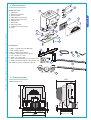
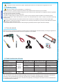
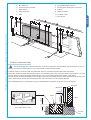
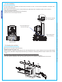
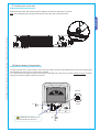
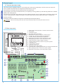
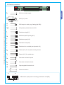
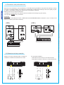
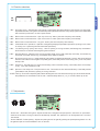
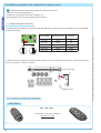
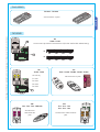
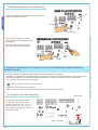
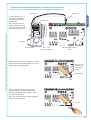
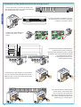
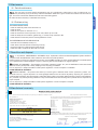
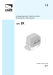
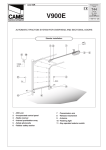
AUTOMATION WITH “PRATICO SYSTEM” FOR SLIDING GATES BK SERIES INSTALLATION MANUAL BK-1200P “IMPORTANT SAFETY INSTRUCTIONS FOR INSTALLATION” “CAUTION: IMPROPER INSTALLATION MAY CAUSE SERIOUS DAMAGE, FOLLOW ALL INSTALLATION INSTRUCTIONS CAREFULLY” “THIS MANUAL IS ONLY FOR PROFESSIONAL INSTALLERS OR QUALIFIED PERSONS” 1 Legend ENGLISH This symbol indicates sections to be read with particular care. This symbol indicates sections concernig safety This symbol indicates notes to communicate to users. 2 Destination and limits of use The BK-1200P gearmotor is designed to automate sliding gates for residential and condominium complexes. The use of this product for purposes other than the one intended and installation carried out in a manner other than as instructed in this technical manual are prohibited. 2.2 Limits of use For intensive or condominium use: maximum gate weight 1200 kg with maximum length of 14 meters. 3 Standard followed The following standard were complied with for this product: EN 12978, UNI EN 954-1, CEI EN 60335-1, UNI EN 12453. 4 Description 4.1 Gearmotor The BK-1200P ratiomotor is designed and built by CAME CANCELLI AUTOMATICI S.p.A. and it meets the safety standards in force. Guaranteed 24 months if not tampered with. The case consists partly of cast aluminium, inside of which operates the non-reversible electromechanical gearmotor, and partly of a covering in ABS plastic inside of which is an electronic card, the transformer and the emergency battery holder. The BK-1200P ratiomotor may be supplied with complementary accessories such as: 001 R001 - Lock cylinder with DIN keys; 001 BSF - Braking device for gates installed on a sloping surface; 001 BRC5/10/15 - Power supply cable winding device for sensitive safety profiles; 001 B4353 - Chain transmission device; 009 CGZ - Galvanized steel 22 x 22 module 4 rack; 009 CGZS - Galvanized steel 30 x 8 module 4 rack with fastening screws, holes and supports; 009 CCT - Simple 1/2” chain; 009 CGIU - 1/2” chain joint. Important! Check that the safety equipment and accessories are CAME originals; this is a guarantee that also makes the system easy to set up and upkeep. 4.2 Technical information GEARMOTOR Power supply: 230V A.C. 50/60Hz Motor power supply: 230V A.C. 50/60Hz Max. absorption: 3,3 A Rated power: 380 W Max. torque: *31 Nm Reduction ratio: 1/11 Push: 850 N Max. speed: 14,5 m/min Operation intermittence: 30% Protection level: IP54 Weight: 18 kg Condenser: 31,5 µF Engine thermoprotection: 150° C * Obtained with CAME control panel. Operating temperature: # 2 # All the data and information contained herein is considered subject to change at any time and at our discretion 2.1 Destination 4.3 Parts description 3 GEARMOTOR UNIT 2 1 10 6 9 7 8 ACCESSORIES 1 - R001 - Cylinder lock with DIN keys 3 2 - BSF - Braking device 3 - BRC - Cable winding device 4 - B4353 - Chain transmission device 5 - CCT - Simple 1/2” chain 6 - CGIU - 1/2” chain joint 7 - CGZ - Galvanized steel 22 x 22 module 4 rack 8 - CGZS - Galvanized steel 30 x 8 module 4 rack with fastening screws, holes and supports 5 6 1 2 8 7 4 4.4 Size measurements Measurements in mm #!-% MAX All the data and information contained herein is considered subject to change at any time and at our discretion 5 4 ENGLISH 1 - Gearmotor 2 - Board cover support 3 - End-stop flaps 4 - ZBK8 basic control board 5 - Electric board front cover 6 - Release door 7 - Base plate 8 - Securing screws 9 - Plates for securing screws 10 - Nuts 3 5 Installation Installation must be carried out by expert qualified personnel and in full observance of regulations in force. Before proceeding with the installation, it is necessary to: • Make sure the door is rigid and compact and that the sliding wheels are well oiled and in good condition. • The ground guide must be well fastened to the ground, fully on the surface for the entirety of its length and without irregularities that might obstruct the gate’s movement. • The upper guide runners must not create friction. • Provide for a gate stopper for opening and one for closing, and for the path of electrical cables as per standard system. • Make sure the point in which the ratiomotor is fixed is in an area protected from shocks or bumps, and that the anchoring surface is solid. • Provide for suitable omnipolar disconnection device with more than 3 mm between contacts to section power supply. • Connections inside the case made for protection circuit continuity are allowed as long as they include additional insulation with respect to other internal drive parts. • Install suitable tubes and ducts for electric cable passage to guarantee protection against mechanical damage. 5.2 Tools and materials Make sure all tools and materials necessary are within reach to install the edge in maximum safety, according to regulations in force. The following figure illustrates the minimum equipment for the installer. 5.3 Cable list and minimun thickness Connections Type of cable 230V 2F power supply 24V - 230V flashing lamp Photoelectric cells TX Photoelectric cells RX 24V power supply accessory FROR CEI 20-22 CEI EN 50267-2-1 Control button Antenna connection RG58 Length of cable 1 < 10 m Length of cable 10 < 20 m Length of cable 20 < 30 m 3G x 1,5 mm2 3G x 2,5 mm2 3G x 4 mm2 2 x 0,5 mm2 2 x 1 mm2 2 x 1,5 mm2 2 x 0,5 mm2 2 x 0.5 mm2 2 x 0,5 mm2 4 x 0,5 mm2 4 x 0,5 mm2 4 x 0,5 mm2 2 x 0,5 mm2 2 x 0,5 mm2 2 x 1 mm2 2 x 0,5 mm2 2 x 0,5 mm2 2 x 0,5 mm2 max. 10 m N.B.: An evaluation of the size of the cables with lengths other than the data in the table must be made based on the effective absorption of the connected devices, according to the instructions indicated by the CEI EN 60204-1 standards. For connections that require several loads on the same line (sequential), the size given on the table must be re-evaluated based on actual absorption and distances. 4 All the data and information contained herein is considered subject to change at any time and at our discretion ENGLISH 5.1 Preliminary checks 12345- 67891011- Key-operated selector switch Flashing light indicating door movement Antenna Safety photocells Photocell column Closure stop ENGLISH BK-1200P unit Control board incorporated Radio receiver Limit-switch tabs Rack 5.4 Motor to base anchorage The following applications are only examples, as the space required for unit installation and the accessories vary depending on dimensions and therefore it is up to the installer to select the best solution. Install the screws in the anchor plate and fasten them with a nut, then bend the preformed clamps downwards. Construct a cement foundation that is large enough to accomodate the gear motor (it is a good idea to protrude 50 mm. from the ground). When pouring the foundation, embed the gear motor anchor plate and the relative clamps in the cement. The anchor bolts should be embedded in the concrete in the positions indicated; the drive unit is then attached to this bots. The anchor plate must be perfectly level and absolutly clean; the bolts threads must be completly exposed. N.B.: The flexible tubes for the electrical wiring must be embedded in the base and protude in the correct position. Gate wing Rack-limit MM MM Cables MM All the data and information contained herein is considered subject to change at any time and at our discretion Wall Fixing plate / Anchor stays Concrete base 5 5.5 Unit installation Rack-to-pinion coupling with 1 mm clearance ¿MM #!-% Horizontal adjustment and unit anchorage Vertical adjustment and unit leveling Cable entrances 5.6 Attaching the rack/limit Attach the rack to the gate as described below: - Release the gearmotor (parag. 5.8); - position the rack on the pinion of the gearmotor and slide the gate manually in order to attach the rack along its entire length; - when the rack is attached to the gate, adjust the feet using a screwdriver until the play between the pinion and the rack is correct (1 mm.). N.B.: This position ensures that the weight of the gate does not rest on the gearmotor. - If the rack is already attached, proceed directly to the adju-stment of the rack/pinion coupling. - when the necessary adjustment have been completed, fasten the unit in position by tightening the two anchor bolts. 6 All the data and information contained herein is considered subject to change at any time and at our discretion MM ENGLISH During the initial phase of installation, the feet should protrude by 5-10 mm. in order to allow for alignment, anchorage of the rack and further adjustments. Perfect alignment with the guide rail is made possible by the (paten-ted) built-in regulation system, which consists of: - slots for horizontal adjustment; - threaded steel feet for vertical adjustment and levelling; - plates and bolts for anchorage to the base. 5.7 Attaching the switch tabs Position the limit-switch tabs (whose positions determine the limits of gate travel) on the rack. Note: do not allow the gate to strike the mechanical stops in the open or closed positions. All the data and information contained herein is considered subject to change at any time and at our discretion ENGLISH #!-% #!-% 5.8 Manual release of the gearmotor To open the access door, insert the key A, push down and rotate clockwise. Then release the ratio motor by using key B on the threelobed pin and turning it in the direction indicated. To re-lock the reduction gear, turn key B in the direction indicated until it will move no further, without forcing it: the threesided pin will settle into place at the first movement. RELEASE #!-% BLOCK ! #!-% ATTENTION: the opening of the unblock panel arrests the motor. " 7 6 Control board 6.1 Technical description board ENGLISH This control board is powered by 230V a.c. across terminals L and N, and is protected by a 5A fuse on the main power line. Control systems are powered by low voltage and protected with by a 1A fuse. The total power consumption of 24V accessories must not exceed 40 W. The photoelectric cells can be connected and set up for reopening in closing, partial stop, and total stop phases and in obstacle detection with the engine idle. The board also incorporates other features that can be selected: Automatic closure, partial opening, pre-flashing opening and closing, “maintained action” operations and type of command: Open-stop-close-stop, Open-close-invert, or opening only. Working cycle (80”). Possibility to adjust the automatic closing time, the operating time and partial opening. 1 - Power supply and transformer connection terminal board 2 - 5A line fuse 3 - 1A accessory fuse 4 - Dip-switch "selezione funzioni" 5 - Radiofrequency board coupling for remote control 6 - Trimmer A.C.: automatic closing time adjustment 7 - Trimmer PAR.OP.: partial aperture adjustment 8 - Save button of the radio-codes of the remote control 9 - LED signalling the radio-code of the remote control 10 - Terminal board for battery charge connection 11 - Coupling radio-frequency board for the “pratico system” 12 - 1.6A battery fuse 13 - 315mA control unit fuse 14 - 1.6A electric block fuse 15 - LED 230V power-supply signal 16 - Terminal boards connecting the electrical lock, end stop and accessories 17 -LED signalling the radio-code of the “pratico system” 18 - Save button of the radio-code of the “pratico system” Grey Brown 6.2 Main components Orange Violet Blue White Red Black , . 5 6 7 % ,4 ,4 #4 63 6& 1 43 0 # # %" %" &# &! & %,%#42)# ",/#+ ! !##%33/2)%3 ! ,).% &53% 2 16 10 !& "/!2$M! "!44%29! 14 5 3 12 13 #/.42/, "/!2$ :"+ 15 18 #( 17 11 /. /04)-% 8 !# 0!2/0 6 7 !& 4 8 9 All the data and information contained herein is considered subject to change at any time and at our discretion Important! - Shut off the mains power and disconnect the batteries before servicing the inside of the unit. 6.3 Electrical connections . , 5 7 % 43 0 # # %" %" &# &! & ENGLISH L N 6 230 V (a.c.) power supply U W V M 230 V (a.c.) motor All the data and information contained herein is considered subject to change at any time and at our discretion (Condenser) W E1 230V output in motion (e.g. flashing light 25W) +10 -11 24V powering accessories max. 40W 1 2 Pushbutton stop (N.C.) 2 3P Pushbutton partial opening (N.O.) 2 3 Pushbutton open (N.O.) 2 4 Pushbutton close (N.O.) 2 7 Pushbutton for controlled (see dip-switch 2-3) 2 C1 Contact (N.C.) for «re-aperture during closure» 2 C3 Contact (N.C.) for «partial stop» F FA Connection limit switch opens F FC Connection limit switch closes EB EB Output supplied for electric lock Antenna connection 48 28 48 48 # .# N.B. Maintain polarity when connecting photoelectric cells (DIR) 9 6.4 Photoelectric cells performance test ENGLISH Allows the control assembly to check the efficiency of the safety devices (photoelectric cells) after each opening or closing command. A possible photoelectric cell malfunction is identified with via LED indicator flashing on the control panel (ref. point 10, page 8), consequently cancelling any remote control or pushbutton commands. Electrical connection for safety test activation: - photoelectric cell transmitters and receivers must be connected in the following way (see scheme) - turn dip-switch 9 to ON to carry out the test. IMPORTANT: when carrying out the safety test function, CHECK that there are NO BRIDGES between contacts N.C.: and, if not used, on the relative dip switches (see functions selection). # .# ./ &53)"),%M! 48 # .# 48 48 430# 43 0 6.5 Gearmotor end-stop connection Gearmotor end-stop assembly already connected for installation on the left-hand side seen from inside. U W V FA FC NC NC F NC FC NC F U W V COM COM 10 FA For right-hand installation: - reverse FA-FC of the end stops on the terminal board; - reverse the U-V phases of the motor on the terminal board. M M All the data and information contained herein is considered subject to change at any time and at our discretion $/# $)2 6.6 Function selections 5 . , 6 7 % ,4 ,4 #4 63 6& 43 0 # # ,).% &53% %" %" &# &! & %,%#42)# ",/#+ ! !##%33/2)%3 ! !& "/!2$M! "!44%29! /. #/.42/, "/!2$ :"+ ENGLISH ON OFF #( /. /04)-% !# !& 0!2/0 All the data and information contained herein is considered subject to change at any time and at our discretion 1 ON - Automatic closing - The automatic closing timer is automatically activated at the end of the opening cycle. The preset, adjustable automatic closing time is automatically interrupted by the activation of any safety system, and is deactivated after a total stop command or in case of power failure; 2 ON - Radio function command and/or “open-stop-close-stop” button (with radio-frequency card inserted). 2 OFF - Radio function command and/or “open-close-inversion” button (with radio-frequency card inserted). 3 ON - Radio function command and/or “only open” button (with radio-frequency card inserted). 4 ON - “Maintained Action” operations - Operation of the gate by keeping the pushbutton pressed for opening on 2-3, button for closing on 2-4 (excluding the radio transmitter operations). 5 ON - “Pre-flashing during opening and closing” - After an opening or closing command, the flashing lamp connected to W-E1 flashes for 5 seconds before beginning the manoeuvre. 6 ON - Obstacle detection - With the motor not running (gate closed, open or after a total stop command), this hinders any movement if the safety devices (e.g. photoelectric cells) detect an obstacle. 7 OFF Re-opening during closure - If the photoelectric cells identify an obstacle while the bar is closing, they will reverse the direction of movement until the gate is completely open; insert safety device on the clamp (2-C1); if not used, select the dip in ON. 8 OFF - Partial stop - The gate stops if in motion with resulting order of automatic closing, insert safety device on the clamp (2-C3); if not used, set the dip to ON. 9 OFF - Operation of the safety test of the photoelectric cells - The central unit can check the efficiency of the safety devices (photoelectric cells) after every opening or closing command. 10 OFF- Total stop - This function stops the gate, with the resulting exclusion of an automatic closing cycle; to resume movement, the pushbuttons or transmitters must be used. Insert the safety device on (1-2); if not used, set the dip to ON. 6.7 Adjustments , . 5 6 7 % ,4 ,4 #4 63 6& 43 0 ,).% &53% # # %" %" &# &! & %,%#42)# ",/#+ ! !##%33/2)%3 ! !& "/!2$M! "!44%29! #/.42/, "/!2$ :"+ !# #( 0!2/0 /. /04)-% !# !& 0!2/0 - Trimmer A.C. = Automatic closing time. Adjusts the wait time of the gate in the open position, also known as “pause time”; at the end of this time, a closing movement is automatically activated. The “pause time” can be adjusted from 1 second to 140 seconds. - Trimmer PAR.OP. = Partial opening. Adjusts the opening time of the gate. By pressing the partial opening button on 2-3P, the gate will open for a set time between 1 and 15 seconds. 11 7 Installation procedure of the transmitter for remote control Read the three steps below before beginning installation procedures: ENGLISH - prepare the radio board (paragraph 7.1); - procedure for codifying the transmitter (paragraph 7.2); - memorizing the code on the command board (paragraph 7.3). 7.1 Prepare the radio board (AF1) TOP Frequency/MHz Radiofrequecy board Transmitter FM 26.995 AF130 TFM FM 30.900 AF150 TFM AM 433.92 AF43S / AF43SM TAM / TOP AM 433.92 AF43SR ATOMO AM 40.685 AF40 TOUCH TAM 2) The AF1 board must ALWAYS be inserted into the coupling (ref. point 5, page 8) when the power is off because the motherboard only recognises it when it is powered. Radio board (AF1) %,%#42)# ",/#+ ! !& Motherboard 7.2 Procedure for codifying the transmitter SERIE ATOMO AT01 - AT02 - AT04 see instruction sheet inside the pack of AF43SR circuit card 12 CAM E All the data and information contained herein is considered subject to change at any time and at our discretion 1) On AM transmitters operating at 433.92 MHz (TOP and TAM series), position the jumper connection on circuit card AF43S as shown on the sheet. TOUCH SERIES TCH 4024 - TCH 4048 see instructions on pack ENGLISH All the data and information contained herein is considered subject to change at any time and at our discretion TOP SERIES TOP T432M - T312M D 0 0 set the code to dip-switch C and channel to D (P1=CH1 and P2=CH2, default setting) P1 /. 0 0 0 0 set code only /. CH2 CH4 /. CH3 /. CH1 TOP T434M - T314M CH2 /. P2 /. CH1 C /. /. CH3 CH4 TOP T432S - T432SA - T434MA - T432NA - T434NA see instructions on pack P1 = CH1 P2 = CH2 P3 = CH3 P4 = CH4 E CAM C TAM T432 - T434 - T438 - TAM432SA see instruction sheet inside the pack TFM T132 - T134 - T138 T152 - T154 - T158 see instruction sheet inside the pack 13 7.3 Memorizing the code on the command board %,%#42)# ",/#+ ! !& AF1 ENGLISH 1) Keep the "CH1" key pressed on the base card (ref. point 8, page 8), the signal LED will flash. #( CH1 2) Press a transmitter key to send the code; the LED will remain lighted to signal memorization. N.B.: if the code needs to be changed, repeat the sequence described above. %,%#42)# ",/#+ ! !& #( !& Lit LED 8 Installation procedure for the remote control for automatically releasing the motor (pratico system) The “pratico system” automatically releases the automation through the radio transmitter. In the absence of 230V power, pressing the key (the same one memorized for opening the gate) or with another key of the radio transmitter, the electrical lock is activated, releasing the gearmotor and making it possible to manually open the gate. After 15 seconds, the system relocks automatically. Before installation, read the procedures below: - preparation of the radio board (paragraph 8.1); - battery connection and memorization of the code on the control board (paragraph 8.2). 8.1 Preparation of the radio board (AF2) Motherboard Disconnect the 230V power and insert the AF2 radio card (with the same frequency used for AF1 card, ref. par. 7.1, pg.12) in the slot (ref. point 11, pg. 8), the motherboard recognises it only when it is battery powered. !& Radio board (AF2) 14 All the data and information contained herein is considered subject to change at any time and at our discretion Flashing LED 8.2 Battery connection and memorization of the code on the control board Terminal -, + Transformer All the data and information contained herein is considered subject to change at any time and at our discretion ENGLISH 1) Insert the terminal (-, +) connected to the battery to the free coupling of the motherboard. Note: the board must be battery-powered for saving procedures. Check the LED signalling 230V power is off. Electric lock , . 5 6 7 % ,4 ,4 #4 63 6& 43 0 # # %" %" &# &! & Condenser Battery bracket 12V - 1.2 Ah emergency batteries Led 230V power-supply signal 2) Keep the key (ref. point 18, page 8) on the basic board depressed. The signalling LED (ref, point 17, page 8) flashes (intermittent LED). %,%#42)# ",/#+ ! !& Save button of the radio-code of the (pratico system) #( Flashing LED !& AF2 3) Press a key (the same one memorized for opening the gate) on the transmitter to send the code. The LED will remain lighted to signal successful memorization. N.B.: if the code needs to be changed, repeat the sequence described above. %,%#42)# ",/#+ ! !& #( Lit LED !& 15 9 Connection of two paired ratiomotors with a single control 1) Coordinate ratiomotor A and B’s movement direction, changing the rotation of motor B (see paragraph 6.5 ratiomotor/end-stop connection). B A #!-% #!-% #!-% #!-% ENGLISH A , . 5 6 7 % 43 0 # # %" %" &# &! 2) Perform the electric connections on motor A’s control board as instructed in paragraph 6.3 electric connections, page 9. & , . A 3) Perform the same settings and functions (dip-switch) on both boards. 5 6 7 % ,4 ,4 #4 63 6& 43 0 # # %" %" &# &! & %,%#42)# ",/#+ ! !##%33/2)%3 ! ,).% &53% , . !& 5 6 7 % ,4 ,4 #4 63 6& "/!2$M! "!44%29! 0 # # %" %" &# &! & !& #/.42/, "/!2$ :"+ :"+ #( /. "/!2$M! "!44%29! #( !# %,%#42)# ",/#+ ! #/.42/, "/!2$ /04)-% 43 !##%33/2)%3 ! ,).% &53% /. !& 0!2/0 /04)-% !# !& 0!2/0 # # 0 43 0 A !##%33/2)%3 ! # # %" %" %,%#42)# ",/#+ ! &# &! & !& 43 0 # # B !##%33/2)%3 ! "/!2$M! "!44%29! %" %" %,%#42)# ",/#+ ! &# &! & 4) Perform the connections between the two control boards as shown in the figure. Note: the partial opening key (2-3P) should be connected to the control board terminal board of the relevant motor (motor A for opening toward the left, B for opening toward the right). !& "/!2$M! "!44%29! A B 5) Insert the “AFI” radio frequency card into both of the control boards and activate the remote control. Select the type of command on both control boards (see dip-switches 2 and 3). A 16 B 6) For the automation’s release system on both motors, insert an AF2 radio card on motor A’s control board and one on motor B’s and carry out the pratico system installation procedure (see chapter 8, pg.14) on both boards. All the data and information contained herein is considered subject to change at any time and at our discretion B 10 Maintenance 10.1 Periodic maintenance The unit does not require specific maintenance. Only as a precautionary measure and in case of intensive use, it is opportune to periodically (every six months) check that the electric cables are in good condition and that the bolts and nuts are tight, and oil the contact areas between the fixed and mobile sliding pieces. All checks must be recorded (in a dedicated record-book). ENGLISH All the data and information contained herein is considered subject to change at any time and at our discretion 10.2 Problem solving THE GATE DOES NOT MOVE: - check the 230V AC power on the terminals L-N; - check the fuses; - check the 24 V power on terminals 10-11; - check the connection of the stop button; if not used, set the dip 10 to ON; - check the safety device connection (partial stop); if unused, set dip switch 8 to ON - check that the small access panel for blocking/release is closed. THE GATE REMAINS IN THE OPEN POSITION: - automatic closure disabled, see dip no.1; - check all the command devices are working correctly; - ensure that nothing is obstructing the safety devices; - make sure all N.C. contacts are set to ON if not used. 11 Demolition and disposal In its premises, CAME CANCELLI AUTOMATICI S.p.A. implements an Environmental Management System certified in compliance with the UNI EN ISO 14001 standard to ensure environmental protection. Please continue our efforts to protect the environment—which CAME considers one of the cardinal elements in the development of its operational and market strategies—simply by observing brief recommendations as regards disposal: DISPOSAL OF PACKAGING – The packaging components (cardboard, plastic, etc.) are all classifiable as solid urban waste products and may be disposed of easily, keeping in mind recycling possibilities. Prior to disposal, it is always advisable to check specific regulations in force in the place of installation. PLEASE DISPOSE OF PROPERLY! PRODUCT DISPOSAL – Our products are made up of various types of materials. Most of them (aluminium, plastics, iron, electrical wires, etc.) may be disposed of in normal garbage collection bins and can be recycled by disposing of in specific recyclable material collection bins and disposal in authorized centres. Other components (electrical boards, remote control batteries, etc.), however, may contain polluting substances. They should therefore be removed and given to qualified service companies for proper disposal. Prior to disposal, it is always advisable to check specific regulations in force in the place of disposal. PLEASE DISPOSE OF PROPERLY! 12 Manufacturer’s warranty MANUFACTURER’S DECLARATION As per Enclosure II B of Machinery Directive 98/37/CE Date of the present declaration 07/12/2001 Enclosed with the technical documentation (the original copy of the Declaration is available on request) Also, they furthermore represent and warrant that the product/s that are the subject of the present Declaration are manufactured in the respect of the following main harmonized provisions: The representatives of CAME Cancelli Automatici S.p.A. via Martiri della Libertà, 15 31030Dosson di Casier - Treviso - ITALYtel (+39) 0422 4940 - fax (+39) 0422 4941 internet: www.came.it - e-mail: [email protected] Hereby declare, under their own respons ibility, that the product/s called ... BK-1200P R001 - BSF - BRC5 - BRC10 - BRC15 - B4353 CGZ - CGZS - CCT - CGIU … comply with the Italian National Legal Provisions that transpose the following Community Directives (where specifically applicable): MACHINERY DIRECTIVE 98/37/CE LOW VOLTAGE DIRECTIVE 73/23/EEC - 93/68/EEC LECTROMAGNETIC COMPATIBILITY DIRECTIVE 89/336/EEC - 92/31/EEC R&TTE DIRECTIVE 1999/5/CE EN 292 PART 1 AND 2 EN 12453 EN 12445 EN 12978 EN 60335 - 1 EN 60204 - 1 EN 61000 - 6 - 2 EN 61000 - 4 - 4 EN 61000 - 4 - 5 MACHINERY SAFETY. INDUSTRIAL, COMMERCIAL AND OTHER CLOSING MECHANISMS. INDUSTRIAL, COMMERCIAL AND OTHER CLOSING MECHANISMS. SAFETY DEVICES FOR POWER OPERATED DOORS AND GATES .... SAFETY IN APPARATUSES FOR HOME USE. MACHINERY SAFETY. ELECTROMAGNETIC COMPATIBILITY. ELECTROMAGNETIC COMPATIBILITY. ELECTROMAGNETIC COMPATIBILITY. IMPORTANT CAUTION! It is forbidden to market/use product/s that are the subject of this declaration before completing and/or incorporating them in total compliance with the provisions of Machinery Directive 98/37/CE Signatures of the Representatives TECHNICAL MANAGER Mr. Gianni Michielan MANAGING DIRECTOR Mr. Paolo Menuzzo 17 CAME UNITED KINGDOM LTD UNIT 3, ORCHARD BUSINESS PARK TOWN STREET, SANDIACRE NOTTINGHAM - NG10 5BP - U.K. Tel 0044 115 9210430 Cod. 119BT86 ver. 1.0 03/06 © CAME CANCELLI AUTOMATICI Fax 0044 115 9210431