1
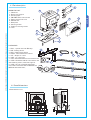
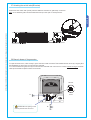
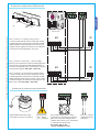
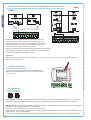
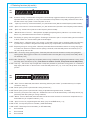
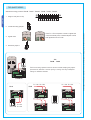
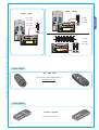
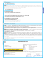
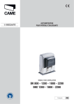
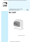
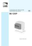
AUTOMATION FOR SLIDING GATES
BK
INSTALLATION MANUAL
BK 800 - 1200 - 1800 - 2200
BKE 1200 - 1800 - 2200
“IMPORTANT SAFETY INSTRUCTIONS FOR INSTALLATION”
“CAUTION: IMPROPER INSTALLATION MAY CAUSE SERIOUS DAMAGE, FOLLOW ALL INSTALLATION INSTRUCTIONS CAREFULLY”
“THIS MANUAL IS ONLY FOR PROFESSIONAL INSTALLERS OR QUALIFIED PERSONS”
1 Legend
ENGLISH
This symbol indicates sections to be read with particular care.
This symbol indicates sections concernig safety
This symbol indicates notes to communicate to users.
2 Destination and limits of use
The BK-BKE gearmotor is designed to automate sliding gates for residential and condominium complexes.
The use of this product for purposes other than the one intended and installation carried out in a manner other than as
instructed in this technical manual are prohibited.
2.2 Limits of use
Maximum gate weight 2200 kg with maximum length of 13 meters.
3 Standard followed
The following standard were complied with for this product: EN 12978, UNI EN 954-1, CEI EN 60335-1, UNI EN 12453.
4 Description
4.1 Gearmotor
The BK-BKE gearmotor is designed and built by CAME CANCELLI AUTOMATICI S.p.A. and it meets the safety standards in force.
Guaranteed 24 months if not tampered with.
The case consists partly of cast aluminium, inside of which operates the non-reversible electromechanical gearmotor, and partly
of a covering in ABS plastic inside of which is an electronic card and the transformer.
There are 4 versions of this unit:
BK800 – automated unit with M4 pinion module, max capacity 800 kg;
BK-BKE 1200/1210 – Automated unit with M4 pinion module, max capacity 1200 kg;
BK-BKE 1800/1810 – Automated unit with M4 pinion module, max capacity 1800 kg;
BK-BKE 2200/2210 – Automated unit with M6 pinion module, max capacity 2200 kg;
The BK-BKE gearmotor may be supplied with complementary accessories such as:
001 R001 - Lock cylinder with DIN keys;
001 BSF - Braking device for gates installed on a sloping surface;
001 BRC5/10/15 - Power supply cable winding device for sensitive safety profiles;
001 B4353 - Chain transmission device;
009 CGZ - Galvanized steel 22 x 22 module 4 rack;
009 CGZS - Galvanized steel 30 x 8 module 4 rack with fastening screws, holes and supports;
009 CGZ6 - 30 x 30 module M6 galvanised rack made of laminated steel for BK2200 and BKE2200 automated units;
009 CCT - Simple 1/2” chain;
009 CGIU - 1/2” chain joint.
Important! Check that the safety equipment and accessories are CAME originals; this is a guarantee that also makes the system
easy to set up and upkeep.
4.2 Technical information
GEARMOTOR
WEIGHT
POWER
SUPPLY
CURRENT
POWER
DUTY CICLE
MAX
TORQUE
BK-800
21 Kg.
230 V a.c.
4,5 A
520 W
intensive service
* 28 Nm
800 N
230 V a.c.
3,3 A
380 W
* 31 Nm
850 N
BK-BKE 1200
BK-BKE 1800
120 V a.c.
5,6 A
310 W
230 V a.c.
4,2 A
480 W
19,5 Kg.
BK-BKE 1810
BK-BKE 2200
PUSH
MAX
SPEED
CONDENSER
2
IP54
-20° C
+55° C
100 µF
* 42 Nm
1/31
1150 N
50%
10,5
m/min
31,5 µF
120 V a.c.
8A
440 W
* 40 Nm
1100 N
140 µF
230 V a.c.
5,1 A
580 W
* 54 Nm
1500 N
35 µF
120 V a.c.
9,1 A
500 W
* 51 Nm
1400 N
160 µF
*Obtained with CAME control panel.
OPERATING
TEMPERATURE
22 µF
21 Kg.
BK-BKE 2210
PROTECTION
LEVEL
25 µF
18 Kg.
BK-BKE 1210
REDUCTION
RATIO
All the data and information contained herein is considered subject to change at any time and at our discretion
2.1 Destination
4.3 Parts description
3
GEARMOTOR UNIT
2
1
10
6
9
7
8
ACCESSORIES
1 - R001 - Cylinder lock with DIN keys
3
2 - BSF - Braking device
3 - BRC - Cable winding device
4 - B4353 - Chain transmission device
5 - CCT - Simple 1/2” chain
6 - CGIU - 1/2” chain joint
7 - CGZ - Galvanized steel 22 x 22 module 4 rack
8 - CGZS - Galvanized steel 30 x 8 module 4 rack
with fastening screws, holes and supports
9 - CGZ6 - 30 x 30 module M6 galvanised
rack made of laminated steel for BK2200 and
BKE2200 automated units;
5
6
1
2
8
7
4
9
4.4 Overall dimensions
Measurements in mm
#!-%
MAX
All the data and information contained herein is considered subject to change at any time and at our discretion
5
4
ENGLISH
1 - Gearmotor
2 - Board cover support
3 - End-stop flaps
4 - ZBK-ZBKE basic control board
5 - Electric board front cover
6 - Release door
7 - Base plate
8 - Securing screws
9 - Plates for securing screws
10 - Nuts
3
5 Installation
Only expert, qualified personnel must carry out the installation, in full compliance with the applicable law.
ENGLISH
Before actually installing the gate operator, your are required to:
• Check that the leaf is rigid and compact and that the rollers are in good working order and properly greased;
• The gate track must be firmly set into the ground, above ground along its entire length and free of any foreign objects (debris)
that may hamper the gate’s movement;
• The top non-pinch rollers must not cause any friction;
• See to installing physical stops at fully-opened and fully-closed positions and the power supply line trench as per the standard
installation;
• Make sure that the spot were the operator is mounted is located in an area that is protects it from any impacts, and that the
mounting surface be solid;
• See to installing a suitable all-pole disconnector switch, with power isolation contacts more than 3mm apart from each
other;
•
Connections inside of the casing made to provide continuity to the protection circuit are allowed, as long as they have
additional isolation compared to other internal conductive parts;
• Set up suitable tubing and trenching to allow for electrical cables to pass, making sure they are free from any potential mechanical damage.
5.2 Tools and materials
Make sure you have all the tools and materials handy, to carry out the installation in total safety, according to the laws in-force. Below is a drawing of the tools you will need to install the operator.
5.3 Cable list and minimun thickness
Connections
Type of cable
120V-230V 2F power supply
230V flashing lamp
Photoelectric cells TX
Photoelectric cells RX
24V power supply accessory
FROR CEI
20-22
CEI EN
50267-2-1
Control button
Antenna connection
RG58
Length of cable 1 < 10 m Length of cable 10 < 20 m Length of cable 20 < 30 m
3G x 1,5 mm2
3G x 2,5 mm2
3G x 4 mm2
2 x 0,5 mm2
2 x 1 mm2
2 x 1,5 mm2
2 x 0,5 mm2
2 x 0.5 mm2
2 x 0,5 mm2
4 x 0,5 mm2
4 x 0,5 mm2
4 x 0,5 mm2
2 x 0,5 mm2
2 x 0,5 mm2
2 x 1 mm2
2 x 0,5 mm2
2 x 0,5 mm2
2 x 0,5 mm2
max. 50 m
N.B.: An evaluation of the size of the cables with lengths other than the data in the table must be made based on the effective
absorption of the connected devices, according to the instructions indicated by the CEI EN 60204-1 standards.
For connections that require several loads on the same line (sequential), the size given on the table must be re-evaluated based
on actual absorption and distances.
4
All the data and information contained herein is considered subject to change at any time and at our discretion
5.1 Preliminary checks
12345-
67891011-
Key-operated selector switch
Flashing light indicating door movement
Antenna
Safety photocells
Photocell column
Closure stop
ENGLISH
BK or BKE unit
Control board incorporated
Radio receiver
Limit-switch tabs (only for the BK unit)
Rack
5.4 Motor to base anchorage
The following applications are only examples, as the space required for unit installation and the accessories vary depending on dimensions and therefore it is up to the installer to select the best solution.
Install the screws in the anchor plate and fasten them with a nut, then bend the preformed clamps downwards.
Construct a cement foundation that is large enough to accomodate the gear motor (it is a good idea to protrude 50 mm. from the
ground). When pouring the foundation, embed the gear motor anchor plate and the relative clamps in the cement.
The anchor bolts should be embedded in the concrete in the positions indicated; the drive unit is then attached to this bots. The
anchor plate must be perfectly level and absolutly clean; the bolts threads must be completly exposed.
N.B.: The flexible tubes for the electrical wiring must be embedded in the base and protude in the correct position.
Gate wing
Rack-limit
MM
MM
Cables
MM
All the data and information contained herein is considered subject to change at any time and at our discretion
Wall
Fixing plate / Anchor stays
Concrete
base
5
5.5 Unit installation
ENGLISH
During the initial phase of installation, the feet should protrude by 5-10 mm. in order to allow for alignment, anchorage of the
rack and further adjustments.
Perfect alignment with the guide rail is made possible by the (paten-ted) built-in regulation system, which consists of:
- slots for horizontal adjustment;
- threaded steel feet for vertical adjustment and levelling;
- plates and bolts for anchorage to the base.
5÷10 mm.
CAME
Horizontal adjustment
and unit anchorage
Vertical adjustment
and unit leveling
Cable entrances
5.6 Attaching the rack/limit
Attach the rack to the gate as described below:
- Release the gearmotor (parag. 5.8);
- position the rack on the pinion of the gearmotor and slide the gate manually in order to attach the rack along its entire length;
- when the rack is attached to the gate, adjust the feet using a screwdriver until the play between the pinion and the rack is correct
(1÷2 mm.).
N.B.: This position ensures that the weight of the gate does not rest on the gearmotor.
- If the rack is already attached, proceed directly to the adju-stment of the rack/pinion coupling.
- when the necessary adjustment have been completed, fasten the unit in position by tightening the two anchor bolts.
N.B.: op het model BKE moet men de tandlat
beginnen installeren in de helft. Dit om het
mogelijk te maken dat de ENCODER de afstand
detecteert
(maximum looplengte hekken = 13 m)
6
All the data and information contained herein is considered subject to change at any time and at our discretion
Afstand tussen tandwiel en tandlat
Module M4 = 1 mm speling /
Module M6 = 1,5 mm speling
5.7 Attaching the switch tabs (BK series)
Position the limit-switch tabs (whose positions determine the limits of gate travel) on the rack.
Note: do not allow the gate to strike the mechanical stops in the open or closed positions.
All the data and information contained herein is considered subject to change at any time and at our discretion
ENGLISH
#!-%
#!-%
5.8 Manual release of the gearmotor
To open the access door, insert the key A, push down and rotate clockwise. Then release the ratio motor by using key B on
the threelobed pin and turning it in the direction indicated.
To re-lock the reduction gear, turn key B in the direction indicated until it will move no further, without forcing it: the threesided pin will settle into place at the first movement.
RELEASE
#!-%
BLOCK
!
#!-%
ATTENTION: the opening of the
unblock panel arrests the motor.
"
7
6 Control board
ENGLISH
The control board is powered with (120V a.c. or 230V a.c.) across terminals L and N and is protected by fuse on the main
power line (see table).
The control systems are powered by low voltage (24V) and protected by a 1A fuse.
The total power consumption of the 24V accessories must not exceed 20W.
The operating time (interval) is fixed at 150 seconds.
The photocells can be connected and set to re-open during the closing phase, re-open during the opening phase, partial stop,
total stop and obstacle sensing when motor is not running.
Note: if a normally closed safety contact (2-C1, 2-CX o 1-2) is opened, this is indicated by the flashing LED (ref. point 9, main
components).
The ZBKE board autonomously controls a safety function that senses any obstacles which:
- when opening, stops the gate and triggers automatic closing;
- when closing, inverts the direction of movement of the gate until it is fully opened and consequently, automatically closes it.
Warning! After the gate’s direction is inverted three consecutive times, the gate remains opened excluding the automatic
closing function – use the remote control or push button to close the gate.
The board also includes other selectable functions, such as: automatic closing, partial opening, pre-flashing of the opening
and closing phases, “maintained action movement”, phase or courtesy lamp, partial stop or re-closing during opening phase,
master-slave and the following command: open-stop-close-stop, open-close-inversion or only open.
The automatic closing and partial opening times are adjustable.
Warning! Before doing any work inside of the unit, shut off the power supply.
305.4/
&2%./
White
Red
Black
BK / BKE
800 - 1200
1800 - 2200
1210
1810 - 2210
Power supply
230V a.c.
120V a.c.
Line fuse
8A
15A
1 - Terminal block for power line and transformer
2 - Line fuse (see table)
3 - Accessories’ fuse 1A
4 - Dip-switch “function selector”
5 - Socket for radio-frequency remote control board
6 - A.C. Trimmer: to adjust automatic closing time
7 - PAR. OP. Trimmer: to adjust partial opening
8 - Remote control frequency code save button
9 - LED indicator for the remote control frequency code
10 - 630mA control unit fuse
11 - LED indicator for 120V or 230V power supply
12 - Terminal block for connecting limit-switches and accessories
13 - Encoder mother board (ZBKE only)
Grey
Brown
6.2 Main components
Orange
Violet
Blue
12
1
10
2
5
11
3
13
/.
8
8
6
7
/.
4
9
All the data and information contained herein is considered subject to change at any time and at our discretion
6.1 Technical description
6.3 Electrical connections
Connection for gear motor, limit switch or encoder
%
RED
6
7
% %8
(Condenser)
Connection for the limit
switch unit (BK series)
COM
NO
NC
COM
NC
Output for
230V (a.c.)
motor connection
Connection for
encoder (BKE
series)
NO
Modifications to the connection if installing the gear motor on the right side
- Invert the phases of the gear motor (U; V);
- On the BK series, invert wires (FA; FC);
- On the BKE series, invert the wires of the shielded cable (+; -)
ZBKE
RED
%
5
6
7
% %8
ROSSO
&
NERO
&# &!
ORANGE
ZBK
WHITE
All the data and information contained herein is considered subject to change at any time and at our discretion
5
BLACK
RED
&
ENGLISH
&# &!
WHITE
ZBKE
ORANGE
ZBK
(Condenser)
Connection for the limit
switch unit (BK series)
COM
NO
NC
COM
NO
NC
Connection for
encoder (BKE
series)
Output for
230V (a.c.)
motor connection
9
Connections to the systems
43
0
-/4
ENGLISH
Key selector and/or opening button (N.0. contact) – Opens the
gate leaf.
Key selector and/or partial opening button (N.0. contact) - Opens
the gate leaf for pedestrian access (adjustable using the trimmer
PAR.OP.)
Key selector and/or closing button (N.0. contact) – Closes the
gate leaf.
Key selector and/or commands button (N.0. contact) – opens and
closes the gate leaf, by pressing the button or turning the key on
the selector, the gate leaf inverts its direction of motion or stops
depending on the chosen selection made on the dip-switches (see
selecting functions, dips 2 and 3).
Connections to warning and illumination devices
5
Courtesy lamp (Contact output: 230V – 60 V max.)
– Auxiliary connection for suitably positioned external
lamp to increase lighting of the steering area. It remain
lit for a fixed time of 5 minutes and 30 seconds.
DIP 16 ON – DIP 17 OFF
(not included in the BK800 version)
Phase lamp (Contact output: 230V – 60W max.)
– Auxiliary connection for a suitably positioned external
lamp, to increase lighting of the steering area. It stays
on from the moment the gate leaf starts to open until
it is fully closed (including the automatic closing time).
If the automatic closing function is inserted, the light
stays on only while gate is moving.
DIP 17 ON – DIP 16 OFF
(not included in the BK800 version)
10
6
7
% %8 43
0
-/4
Indicator light when gate is open
(contact output: 24V – 3W max.).
Indicates that gate leaf is open, and
turns off when the gate is closed.
Movement flashing light (Contact
output: 230V – 25W max.)
Flashes during the gate’s opening
and closing phases.
All the data and information contained herein is considered subject to change at any time and at our discretion
Stop button (N.C. contact) – Gate leaf stop- button with exclusion of automatic
closing phase, resume motion by pressing the push button or remote control.
Connections to safety devices (DIR photocell)
6
43
0 #8
#
-/4
ENGLISH
6
6
6
48
#
.#
All the data and information contained herein is considered subject to change at any time and at our discretion
Set power supply to
24V a.c./d.c.
RX
(N.C.) contact for “re-opening during closing”
– Input for safety devices such as photocells, sensitive safety edges and other devices compliant with EN
12978 standards. When the gate leaf is closing, opening the contact triggers the inversion of the direction
of movement until the gate leaf is fully open.
(N.C.) contact for “partial stop” – Input for safety
devices such as photocells, sensitive safety edges and
other devices compliant with EN 12978 standards. If
in motion, the gate leaf stops, and automatic closing is
consequently triggered. DIP 8 OFF – DIP 9 ON.
TX
48 # .#
48 RX
TX
48 # .#
48 (N.C.) contact for “re-closing during opening phase”
– Input for safety devices such as photocells, sensitive safety edges and other devices compliant with EN
12978 standards. When gate is opening, if the contact
is opened it triggers an inversion of the direction until
gate is fully closed. DIP 8 OFF – DIP 9 OFF.
Connections for power source and accessories
,
.
5
6
7
% %8
+
Eyelet cable terminal with screw
and washer for ground connection
Electric power
120V – 230W
(a.c.) – 50/60 Hz
Fan (contact output: 230V – 25W) –
Connection for the fan which cools the
gear motor. Each time the gate leaf is
opened, the fan stays on for a fixed time
of 5 minutes and 30 seconds.
DIP 16 ON – DIP 17 OFF
(only for the BK800 version)
-
24V (d.c.) output to
power accessories
(20W max.)
11
6.4 Electrical connection for the check of the operating state of the photocells
$)2
&53)"),%M!
48 # .#
43
0
48
48
-/4
43
0
-/4
Each time an open or close command is given, the circuit board
checks the efficiency of the safety devices (i.e. photocells). The
flashing led indicator on the control panel indicates an anomaly of
the photocells (Ref. to point 9, p. 8), consequently it cuts off any
command from the remote control or push button.
Electrical connection to test the state of the safety check of the photocells:
- the transmitter and receiver, must be connect as shown in the drawing;
- select dip 13 to ON to activate the test function.
IMPORTANT:
When running the safety test function, exclude the N.C. contacts, if not used, by acting on their corresponding DIPs (see
para. 6.7 selecting functions).
305.4/
To vary the motor torque, move the faston indicated by the
black wire (connected to terminal CT) to one of the 4 positions:
1 min ÷ 4 max.
&2%./
6.5 Motor torque limiter
6.6 Adjustments
0!2/0
!#4
A.C.T. Trimmer = Automatic Closing Time. This adjusts the gate’s stand-by time in the opening phase, a.k.a. “pause time”.
When the time elapses the gate automatically closes. The “pause time” can be adjusted from 1 second to 150 seconds.
PAR. OP. Trimmer = Partial opening. Adjusts the gates opening time. By pressing the partial opening button on 2-3P, the gate
will open for a pre-set time of between 1 and 14 seconds.
With this function, the automatic closing time will very as follows:
- when dip 12 is set to ON, after a partial opening, the closing time is independent of the A.C.T. Trimmer adjustment and of the
setting of DIP 1, and is set to 8 seconds;
- when dip 12 is set to OFF, after a partial opening, the automatic closing time is adjustable only is, dip 1 is set to the ON position.
12
All the data and information contained herein is considered subject to change at any time and at our discretion
#
./
.#
ENGLISH
$/#
6.7 Selecting functions (dip-switch)
ON
OFF
ON
1 2 3 4 5 6 7 8 9 10
ON
11 12 13 14 15 16 17 18 19 20
2 ON -
ENGLISH
1 ON - Automatic Closing – the automatic closing timer is automatically triggered at the end of the opening phase. The
adjustable set time of operation, is in any case subordinate to the operation of any safety accessories and is excluded after a total “stop” phase or if the main power is cut off.
“Open-stop-close-stop” function with button (2-7) and remote control (that has a radio frequency board inserted).
2 OFF - “Open-close-inversion” function with button (2-7) and remote control (that has a radio frequency board inserted).
All the data and information contained herein is considered subject to change at any time and at our discretion
3 ON - “Open only” remote control (that has a radio frequency board inserted).
4 ON - “Maintained action” function” – Gate operation by keeping the opening button pressed on 2-3, and the closing
button 2-4, (it excludes the remote control from operating).
5 ON - Pre-flashing in opening and closing phase – Following a command to open or close, the flashing device connected
to W-E1, flashes for 5 seconds before gate movement begins.
6 ON - Obstacle sensor – When the motor is not running (i.e. the gate is closed, open or following a total stop command),
it prevents any movement of the gate if the safety devices (e.g. the photocells) sense and obstacle in the way.
7 OFF - Reopening during the closing phase – When the photocells sense and obstacle as the arm is closing, they trigger
an inversion of direction movement until full opening is achieved; insert the safety device into terminal (2-C1); if
not used, set dip switch to ON.
8 OFF / 9 OFF – Re-closing during opening phase – When the photocells sense an obstacle in the way during the gate’s
opening phase, they trigger an inversion of movement direction until the gate is fully closed; insert safety device
into terminal (2-CX);
8 OFF / 9 ON – Partial stop – The gate stops completely when moving consequently triggering the automatic closing, insert
the safety device into terminal (2-CX); (if the devices on 2-CX are not used, set dip switch 8 to the ON position)
10 OFF- Total stop – This function stops the gate and consequently excludes any automatic closing phase; for movement to
begin again press button or remote control. Insert the safety device into (1-2); if not used, set dip switch to the ON
position.
ON
OFF
ON
ON
1 2 3 4 5 6 7 8 9 10
11 12 13 14 15 16 17 18 19 20
11 OFF - “Slave” function deactivated, the board is exclusively piloted by the “master” (to be activated only for coupled
connection, see p.15);
12 ON - Partial opening function (the automatic closing is fixed to 8”);
12 OFF - Partial opening function (the automatic closing is adjustable through the trimmer, if inserted);
13 ON - Functioning of the photocells’ safety test – Enables the control unit to test the efficiency of the safety devices (e.g.
photocells) after each opening or closing command;
14 OFF - “Master” function deactivated, the board takes over all the control functions as concerns two coupled motors (to
be activated only for coupled connection, p. 15);
15 ON - “Spare” function for programming the limit switch (only for the ZBKE series, p. 14);
16 ON /17 OFF - Courtesy lamp function activated; (16 OFF deactivated)
17 ON / 16 OFF - Phase lamp function activated; (17 OFF deactivated)
18
Not connected
19
Not connected
20
Not connected
13
7 Programming of limit switches for ZBKE board
1) Close the engage door-panel and insert
DIP switch 15 to the ON position, the led
indicator of the radio code starts flashing.
/.
2) Manually close the gate leaf, press the “CLOSE” button, the
led indicator keeps flashing as long as button is kept pressed.
3) Manually open the gate leaf, press the “OPEN” button, the led code
indicator keeps flashing as long as the button is kept pressed.
N.B.: By pressing the “OPEN” button during this procedure, the led
indicator does not turn on; invert the phases of the motor (U; V) and
of the Encoder (+; -), see para. 6.3 electrical connections of the motor
and encoder, p. 9.
/.
/.
4) Re-set DIP switch 15 to the OFF
position.
5) When the programming procedure is finished, open the door panel and block the gear motor with
key B by turning it in the indicated
direction and close the door panel.
BLOCK
14
All the data and information contained herein is considered subject to change at any time and at our discretion
ENGLISH
/.
8 Connection of two coupled gear motors with single control
1) Coordinate the direction of gear motors “A” and
“B”, by changing the rotation of motor “B” (see connection for the gear motor and limit switches, p. 9).
/.
All the data and information contained herein is considered subject to change at any time and at our discretion
2) Establish which motor, “A” or
“B” will be the master (or pilot),
set dip switch 14 to the ON on
position on the control board.
“Master” means the motor that
controls both gates, while on
the control board of the 2nd
motor, position dip switch 11 to
the ON position to place it into
a “slave” state.
N.B.: Make sure that the radiofrequency board is inserted
only into the Master board.
B
/.
“MASTER”
“SLAVE”
A
,
3) Wire the electrical connections
and the normally used selections
only on the MASTER terminal
board;
.
5
6
% %8 43
7
0
-/4
&# &!
&
# #8
" "
“MASTER”
A
B
/.
/.
/.
“MASTER”
43
/.
“SLAVE”
0
-/4
5) Make sure that all the dip switches on
the board of motor 2 are OFF, except for dip
switch 11.
Important: adjust the limit switches of the
motors so that the MASTER motor’s gate leaf
closes after that of the SLAVE.
43
B
0
/.
4) Wire the electrical
connections between
the terminal boards, as
shown in the figure.
Note: make sure that the
automatic closing is triggered by the master and
deactivated in the slave.
-/4
/.
“SLAVE”
15
ENGLISH
A
B
A
9 Installation procedure of the transmitter for remote control
ENGLISH
" "
Read the three steps below before beginning installation procedures:
- prepare the radio board (paragraph 9.1);
- procedure for codifying the transmitter (paragraph 9.2);
- memorizing the code on the command board (paragraph 9.3).
9.1 Prepare the radio board AF
1) On AM transmitters operating at
433.92 MHz (TOP and TAM series),
position the jumper connection on
circuit card AF43S as shown on the
sheet.
TOP
2) The AF board must ALWAYS
be inserted into the coupling
(ref. point 5, page 8) when
the power is off because the
motherboard only recognises
it when it is powered.
TAM
Frequency/MHz
Radiofrequecy board
Transmitter
FM 26.995
AF130
TFM
FM 30.900
AF150
TFM
AM 26.995
AF26
TOP
AM 30.900
AF30
TOP
AM 433.92
AF43S / AF43SM
TAM / TOP
AM 433.92
AF43SR
ATOMO
AM 40.685
AF40
TOUCH
Radio board AF
Motherboard
16
All the data and information contained herein is considered subject to change at any time and at our discretion
Possible second channel
output from the radio receiver
(contact N.O.) Contact output: 5A-24V (d.c.).
Input for the remote control’s antenna
– For opening and closing of the gate
leaf using the remote control. Connect the RG58 cable to the terminal of
the antenna with “AF” radio-frequency inserted in the motherboard.
9.2 Procedure for codifying the transmitter
TOP SERIES
D
0
ENGLISH
TOP
T432M - T312M
0
set the code to dip-switch C and channel to D (P1=CH1 and P2=CH2, default setting)
All the data and information contained herein is considered subject to change at any time and at our discretion
P1
/.
0
0
0
0
set code only
/.
CH2
CH4
/.
CH3
/.
CH1
TOP
T434M - T314M
CH2
/.
P2
/.
CH1
C
/.
/.
CH3
CH4
TOP
T432S - T432SA - T434MA - T432NA - T434NA
see instructions on pack
P1 = CH1
P2 = CH2
P3 = CH3
P4 = CH4
E
CAM
C
TAM
T432 - T434 - T438 - TAM432SA
see instruction
sheet inside the
pack
TFM
T132 - T134 - T138
T152 - T154 - T158
see instruction sheet inside the
pack
17
TOP QUARTZ SERIES
Standard encoding procedure T262M - T264M - T2622M - T302M - T304M - T3022M
ENGLISH
1 assign a code (also on file)
0
/&&
0
/.
Press P1 or P2 in sequence in order to register the
code; at the tenth pulse, a double beep will confirm
that registration has occurred
3 register code
4 disinserire jumper J
0
TOP
T262M - T302M
0
The first encoding operation must be carried out whilst keeping the jumpers
positioned for channels 1 and 2 as per fig. A; see fig. B for any subsequent
settings on different channels.
FIG.A
P1 = CH3 - P2 = CH2
P1 = CH1 - P2 = CH4
P1 = CH3 - P2 = CH4
FIG.B
P1 = CH1
P2 = CH2
18
P1 = CH1 - P2 = CH3
All the data and information contained herein is considered subject to change at any time and at our discretion
2 connect encoding jumper J
T2622M - T3022M
T264M - T304M
P1 = CH1
0
1° Code
0
0
P1 = CH1
ENGLISH
P2 = CH2
0
P2 = CH2
P3 = CH3
All the data and information contained herein is considered subject to change at any time and at our discretion
P4 = CH4
0
0
0
0
0
/&&
0
/.
2° Code
P3 = CH1
P4 = CH2
ATOMO SERIES
AT01 - AT02 - AT04
see instruction sheet inside the pack of
AF43SR circuit card
CAM
E
TOUCH SERIES
TCH 4024 - TCH 4048
see instructions on pack
19
9.3 Memorizing the code on the command board
ENGLISH
CH1 = Channel for direct commands to a function of the ratiomotor control unit (“open only” / “open-close-invert direction” commands or the “open-stop-close-stop” command, depending on dip-switch 2 - 3
settings).
AF
CH1
Flashing LED
2) Press a transmitter key to send the
code; the LED will remain lighted to signal
memorization.
T1
Lit LED
CH2 = Channel for direct commands to an auxiliary device or for the control of two paired motors,
connected to B1-B2.
3) Repeat the procedure of parts 1
and 2 with the “CH2” key, associating
it wit another transmitter key.
N.B.: if the code needs to be changed, repeat the sequence described
above.
20
T2
CH2
All the data and information contained herein is considered subject to change at any time and at our discretion
1) Keep the "CH1" key pressed on the base
card (ref. point 11, page 12), the signal LED
will flash.
10 Maintenance
10.1 Periodic maintenance
The unit does not require specific maintenance. Only as a precautionary measure and in case of intensive use, it is
opportune to periodically (every six months) check that the electric cables are in good condition and that the bolts and nuts are
tight, and oil the contact areas between the fixed and mobile sliding pieces.
All checks must be recorded (in a dedicated record-book).
ENGLISH
All the data and information contained herein is considered subject to change at any time and at our discretion
10.2 Problem solving
THE GATE DOES NOT MOVE:
- check the 120V or 230V AC power on the terminals L-N;
- check the fuses;
- check the 24 V power on terminals 10-11;
- check the connection of the stop button; if not used, set the dip 10 to ON;
- check the safety device connection (partial stop); if unused, set dip switch 8 to ON
- check that the small access panel for blocking/release is closed.
THE GATE REMAINS IN THE OPEN POSITION:
- automatic closure disabled, see dip no.1;
- check all the command devices are working correctly;
- ensure that nothing is obstructing the safety devices;
- make sure all N.C. contacts are set to ON if not used.
11 Demolition and disposal
In its premises, CAME CANCELLI AUTOMATICI S.p.A. implements an Environmental Management System certified in
compliance with the UNI EN ISO 14001 standard to ensure environmental protection.
Please continue our efforts to protect the environment—which CAME considers one of the cardinal elements in the development
of its operational and market strategies—simply by observing brief recommendations as regards disposal:
DISPOSAL OF PACKAGING – The packaging components (cardboard, plastic, etc.) are all classifiable as solid urban waste
products and may be disposed of easily, keeping in mind recycling possibilities.
Prior to disposal, it is always advisable to check specific regulations in force in the place of installation.
PLEASE DISPOSE OF PROPERLY!
PRODUCT DISPOSAL – Our products are made up of various types of materials. Most of them (aluminium, plastics, iron,
electrical wires, etc.) may be disposed of in normal garbage collection bins and can be recycled by disposing of in specific recyclable material collection bins and disposal in authorized centres. Other components (electrical boards, remote control batteries,
etc.), however, may contain polluting substances. They should therefore be removed and given to qualified service companies for
proper disposal.
Prior to disposal, it is always advisable to check specific regulations in force in the place of disposal.
PLEASE DISPOSE OF PROPERLY!
12 Manufacturer’s warranty
MANUFACTURER’S DECLARATION
As per Enclosure II B of Machinery Directive 98/37/CE
Date of the present declaration 07/12/2001
Enclosed with the technical documentation (the original copy of the Declaration is available on request)
The representatives of
CAME Cancelli Automatici S.p.A.
via Martiri della Libertà, 15
31030Dosson di Casier - Treviso - ITALYtel
(+39) 0422 4940 - fax (+39) 0422 4941
internet: www.came.it - e-mail: [email protected]
Hereby declare, under their own respons ibility, that the product/s called ...
BK800 - BK1200/1210 - BK1800/1810 - BK2200/2210
BKE1200/1210 - BKE1800/1810 - BKE2200/2210
R001 - BSF - BRC5 - BRC10 - BRC15 - B4353
CGZ - CGZS - CGZ6 - CCT - CGIU
… comply with the Italian National Legal Provisions that transpose the
following Community Directives (where specifically applicable):
MACHINERY DIRECTIVE 98/37/CE
LOW VOLTAGE DIRECTIVE 73/23/EEC - 93/68/EEC
LECTROMAGNETIC COMPATIBILITY DIRECTIVE 89/336/EEC - 92/31/EEC
R&TTE DIRECTIVE 1999/5/CE
Also, they furthermore represent and warrant that the product/s that are the subject of the present Declaration
are manufactured in the respect of the following main harmonized provisions:
EN 292 PART 1 AND 2
EN 12453
EN 12445
EN 12978
EN 60335 - 1
EN 60204 - 1
EN 61000 - 6 - 2
EN 61000 - 4 - 4
EN 61000 - 4 - 5
MACHINERY SAFETY.
INDUSTRIAL, COMMERCIAL AND OTHER CLOSING MECHANISMS.
INDUSTRIAL, COMMERCIAL AND OTHER CLOSING MECHANISMS.
SAFETY DEVICES FOR POWER OPERATED DOORS AND GATES ....
SAFETY IN APPARATUSES FOR HOME USE.
MACHINERY SAFETY.
ELECTROMAGNETIC COMPATIBILITY.
ELECTROMAGNETIC COMPATIBILITY.
ELECTROMAGNETIC COMPATIBILITY.
IMPORTANT CAUTION!
It is forbidden to market/use product/s that are the subject of this declaration before completing and/or
incorporating them in total compliance with the provisions of Machinery Directive 98/37/CE
Signatures of the Representatives
TECHNICAL MANAGER
Mr. Gianni Michielan
MANAGING DIRECTOR
Mr. Paolo Menuzzo
21
Cod. 119BS04 ver. 4.0 01/06 © CAME CANCELLI AUTOMATICI