1
Setup and Installation Guide
HP BladeSystem bc1500 Blade PC and PC
Blade Enclosure
Document Part Number: 399089-003
December 2005
This guide provides step-by-step instructions for installation, and
reference information for operation, troubleshooting, and future
upgrades for the HP Consolidated Client Infrastructure (CCI)
solution.
© Copyright 2005 Hewlett-Packard Development Company, L.P.
The information contained herein is subject to change without notice.
Microsoft and Windows are U.S. registered trademarks of Microsoft
Corporation.
AMD Athlon 64 and HyperTransport are U.S. registered trademarks of
Advanced Micro Devices, Inc.
The only warranties for HP products and services are set forth in the express
warranty statements accompanying such products and services. Nothing herein
should be construed as constituting an additional warranty. HP shall not be liable
for technical or editorial errors or omissions contained herein.
This document contains proprietary information that is protected by copyright.
No part of this document may be photocopied, reproduced, or translated to
another language without the prior written consent of Hewlett-Packard
Company.
Å
WARNING: Text set off in this manner indicates that failure to follow
directions could result in bodily harm or loss of life.
Ä
CAUTION: Text set off in this manner indicates that failure to follow
directions could result in damage to equipment or loss of information.
Setup and Installation Guide
HP BladeSystem bc1500 Blade PC and PC Blade Enclosure
Third Edition (December 2005)
Document Part Number: 399089-003
Contents
1 About This Guide
Audience Assumptions . . . . . . . . . . . . . . . . . . . . . . . . . . . . . . . . . . . . . . . . . . . . . . . . .
Important Safety Information . . . . . . . . . . . . . . . . . . . . . . . . . . . . . . . . . . . . . . . . . . . .
Symbols on Equipment . . . . . . . . . . . . . . . . . . . . . . . . . . . . . . . . . . . . . . . . . . . . . . . . .
Rack Stability . . . . . . . . . . . . . . . . . . . . . . . . . . . . . . . . . . . . . . . . . . . . . . . . . . . . . . . .
Symbols in Text. . . . . . . . . . . . . . . . . . . . . . . . . . . . . . . . . . . . . . . . . . . . . . . . . . . . . . .
Related Documents . . . . . . . . . . . . . . . . . . . . . . . . . . . . . . . . . . . . . . . . . . . . . . . . . . . .
Getting Help . . . . . . . . . . . . . . . . . . . . . . . . . . . . . . . . . . . . . . . . . . . . . . . . . . . . . . . . .
Technical Support . . . . . . . . . . . . . . . . . . . . . . . . . . . . . . . . . . . . . . . . . . . . . . . . . .
HP Website . . . . . . . . . . . . . . . . . . . . . . . . . . . . . . . . . . . . . . . . . . . . . . . . . . . . . . .
1–1
1–1
1–1
1–3
1–3
1–4
1–4
1–4
1–4
2 HP CCI Solution Technology
Hardware Features. . . . . . . . . . . . . . . . . . . . . . . . . . . . . . . . . . . . . . . . . . . . . . . . . . . . . 2–1
HP PC Blade Enclosure Features . . . . . . . . . . . . . . . . . . . . . . . . . . . . . . . . . . . . . . 2–2
HP BladeSystem bc1500 Blade PC Features . . . . . . . . . . . . . . . . . . . . . . . . . . . . . 2–5
Software Deployment and Management Features. . . . . . . . . . . . . . . . . . . . . . . . . . . . . 2–8
Diagnostic Features . . . . . . . . . . . . . . . . . . . . . . . . . . . . . . . . . . . . . . . . . . . . . . . . . . . 2–10
3 Planning the Installation
Optimum Environment . . . . . . . . . . . . . . . . . . . . . . . . . . . . . . . . . . . . . . . . . . . . . . . . .
Rack Warnings and Cautions . . . . . . . . . . . . . . . . . . . . . . . . . . . . . . . . . . . . . . . . . . . .
HP PC Blade Enclosure Warnings and Cautions . . . . . . . . . . . . . . . . . . . . . . . . . . . . .
Preparing for Software Deployment . . . . . . . . . . . . . . . . . . . . . . . . . . . . . . . . . . . . . . .
HP Rapid Deployment Pack . . . . . . . . . . . . . . . . . . . . . . . . . . . . . . . . . . . . . . . . . .
Alternate Deployment Method . . . . . . . . . . . . . . . . . . . . . . . . . . . . . . . . . . . . . . . .
Shipping Contents . . . . . . . . . . . . . . . . . . . . . . . . . . . . . . . . . . . . . . . . . . . . . . . . . . . . .
Blade Enclosure . . . . . . . . . . . . . . . . . . . . . . . . . . . . . . . . . . . . . . . . . . . . . . . . . . .
Rack-Mounting Hardware . . . . . . . . . . . . . . . . . . . . . . . . . . . . . . . . . . . . . . . . . . .
Blade PCs . . . . . . . . . . . . . . . . . . . . . . . . . . . . . . . . . . . . . . . . . . . . . . . . . . . . . . . .
Setup and Installation Guide
www.hp.com
3–1
3–1
3–3
3–5
3–5
3–5
3–5
3–6
3–6
3–7
iii
Contents
Interconnect Switch . . . . . . . . . . . . . . . . . . . . . . . . . . . . . . . . . . . . . . . . . . . . . . . . 3–8
Optional RJ-45 Patch Panel . . . . . . . . . . . . . . . . . . . . . . . . . . . . . . . . . . . . . . . . . . 3–8
Optional Installation Service . . . . . . . . . . . . . . . . . . . . . . . . . . . . . . . . . . . . . . . . . . . . . 3–8
4 Installing and Cabling the HP CCI Solution
Measuring with the Rack Template. . . . . . . . . . . . . . . . . . . . . . . . . . . . . . . . . . . . . . . . 4–2
Installing the Rack Rails . . . . . . . . . . . . . . . . . . . . . . . . . . . . . . . . . . . . . . . . . . . . . . . . 4–4
Installing the Enclosure into the Rack. . . . . . . . . . . . . . . . . . . . . . . . . . . . . . . . . . . . . . 4–7
Cabling the HP CCI Solution . . . . . . . . . . . . . . . . . . . . . . . . . . . . . . . . . . . . . . . . . . . . 4–9
HP PC Blade Enclosure C-GbE Interconnect Switch Connectors . . . . . . . . . . . . 4–10
Optional RJ-45 Patch Panel . . . . . . . . . . . . . . . . . . . . . . . . . . . . . . . . . . . . . . . . . 4–11
Cabling the Enclosure. . . . . . . . . . . . . . . . . . . . . . . . . . . . . . . . . . . . . . . . . . . . . . 4–12
Installing a Blade PC. . . . . . . . . . . . . . . . . . . . . . . . . . . . . . . . . . . . . . . . . . . . . . . . . . 4–15
Powering Up the HP CCI Solution . . . . . . . . . . . . . . . . . . . . . . . . . . . . . . . . . . . . . . . 4–19
Powering Down the HP CCI Solution. . . . . . . . . . . . . . . . . . . . . . . . . . . . . . . . . . . . . 4–19
Powering Down a Blade PC . . . . . . . . . . . . . . . . . . . . . . . . . . . . . . . . . . . . . . . . . 4–19
Powering Down the Enclosure . . . . . . . . . . . . . . . . . . . . . . . . . . . . . . . . . . . . . . . 4–21
Removing a Blade PC . . . . . . . . . . . . . . . . . . . . . . . . . . . . . . . . . . . . . . . . . . . . . . . . . 4–21
Installing Additional Memory . . . . . . . . . . . . . . . . . . . . . . . . . . . . . . . . . . . . . . . . . . . 4–22
Attaching the Graphics Diagnostic Card and Diagnostic Adapter . . . . . . . . . . . . . . . 4–25
5 Deployment and Management
Blade PC Deployment Options . . . . . . . . . . . . . . . . . . . . . . . . . . . . . . . . . . . . . . . . . . . 5–2
Automated Deployment Using HP Rapid Deployment Pack . . . . . . . . . . . . . . . . . 5–2
Alternate Deployment Methods . . . . . . . . . . . . . . . . . . . . . . . . . . . . . . . . . . . . . . . 5–2
Diagnostic Adapter and Optional Graphics Diagnostic Card. . . . . . . . . . . . . . . . . 5–3
Blade PC Features and Supported Software . . . . . . . . . . . . . . . . . . . . . . . . . . . . . . . . . 5–4
Supported Operating Systems. . . . . . . . . . . . . . . . . . . . . . . . . . . . . . . . . . . . . . . . . 5–4
Computer Setup (F10) Utility . . . . . . . . . . . . . . . . . . . . . . . . . . . . . . . . . . . . . . . . . 5–4
Flashing the Blade PC ROM . . . . . . . . . . . . . . . . . . . . . . . . . . . . . . . . . . . . . . . . 5–16
HP PC Blade Enclosure Integrated Administrator . . . . . . . . . . . . . . . . . . . . . . . . 5–17
Blade PC Event Messages . . . . . . . . . . . . . . . . . . . . . . . . . . . . . . . . . . . . . . . . . . 5–20
HP Systems Insight Manager . . . . . . . . . . . . . . . . . . . . . . . . . . . . . . . . . . . . . . . . 5–21
HP PC Blade Enclosure C-GbE Interconnect Switch
Management Tools and Utilities. . . . . . . . . . . . . . . . . . . . . . . . . . . . . . . . . . . . . . 5–22
iv
www.hp.com
Setup and Installation Guide
Contents
A Regulatory Compliance Notices
Regulatory Compliance Identification Numbers. . . . . . . . . . . . . . . . . . . . . . . . . . . . . .
Federal Communications Commission Notice . . . . . . . . . . . . . . . . . . . . . . . . . . . . . . .
Class A Equipment . . . . . . . . . . . . . . . . . . . . . . . . . . . . . . . . . . . . . . . . . . . . . . . . .
Class B Equipment . . . . . . . . . . . . . . . . . . . . . . . . . . . . . . . . . . . . . . . . . . . . . . . . .
Declaration of Conformity for Products Marked with the
FCC Logo, United States Only . . . . . . . . . . . . . . . . . . . . . . . . . . . . . . . . . . . . . . . .
Modifications . . . . . . . . . . . . . . . . . . . . . . . . . . . . . . . . . . . . . . . . . . . . . . . . . . . . .
Cables . . . . . . . . . . . . . . . . . . . . . . . . . . . . . . . . . . . . . . . . . . . . . . . . . . . . . . . . . . .
Canadian Notice (Avis Canadien) . . . . . . . . . . . . . . . . . . . . . . . . . . . . . . . . . . . . . . . . .
Class A Equipment . . . . . . . . . . . . . . . . . . . . . . . . . . . . . . . . . . . . . . . . . . . . . . . . .
Class B Equipment . . . . . . . . . . . . . . . . . . . . . . . . . . . . . . . . . . . . . . . . . . . . . . . . .
European Union Notice . . . . . . . . . . . . . . . . . . . . . . . . . . . . . . . . . . . . . . . . . . . . . . . . .
Japanese Notice . . . . . . . . . . . . . . . . . . . . . . . . . . . . . . . . . . . . . . . . . . . . . . . . . . . . . . .
Korean Notice . . . . . . . . . . . . . . . . . . . . . . . . . . . . . . . . . . . . . . . . . . . . . . . . . . . . . . . .
Class A Equipment . . . . . . . . . . . . . . . . . . . . . . . . . . . . . . . . . . . . . . . . . . . . . . . . .
Class B Equipment . . . . . . . . . . . . . . . . . . . . . . . . . . . . . . . . . . . . . . . . . . . . . . . . .
Taiwanese Notice . . . . . . . . . . . . . . . . . . . . . . . . . . . . . . . . . . . . . . . . . . . . . . . . . . . . .
Laser Compliance . . . . . . . . . . . . . . . . . . . . . . . . . . . . . . . . . . . . . . . . . . . . . . . . . . . . .
Battery Replacement Notice . . . . . . . . . . . . . . . . . . . . . . . . . . . . . . . . . . . . . . . . . . . . .
A–1
A–1
A–2
A–2
A–3
A–3
A–3
A–4
A–4
A–4
A–4
A–5
A–5
A–5
A–5
A–6
A–6
A–7
B Electrostatic Discharge
Preventing Electrostatic Damage . . . . . . . . . . . . . . . . . . . . . . . . . . . . . . . . . . . . . . . . . B–1
Grounding Methods. . . . . . . . . . . . . . . . . . . . . . . . . . . . . . . . . . . . . . . . . . . . . . . . . . . . B–2
C POST Error Messages
D Troubleshooting
When the Enclosure Does Not Start . . . . . . . . . . . . . . . . . . . . . . . . . . . . . . . . . . . . . . . D–3
Enclosure Diagnostic Steps . . . . . . . . . . . . . . . . . . . . . . . . . . . . . . . . . . . . . . . . . . . . . . D–5
When the Blade PC Does Not Start. . . . . . . . . . . . . . . . . . . . . . . . . . . . . . . . . . . . . . . D–14
Blade PC Diagnostic Steps . . . . . . . . . . . . . . . . . . . . . . . . . . . . . . . . . . . . . . . . . . . . . D–16
Problems After Initial Boot . . . . . . . . . . . . . . . . . . . . . . . . . . . . . . . . . . . . . . . . . . . . . D–21
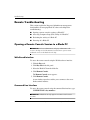
Remote Troubleshooting . . . . . . . . . . . . . . . . . . . . . . . . . . . . . . . . . . . . . . . . . . . . . . . D–22
Opening a Remote Console Session to a Blade PC . . . . . . . . . . . . . . . . . . . . . . . D–22
Accessing the Computer Setup (F10) Utility for a Blade PC . . . . . . . . . . . . . . . . D–23
Setup and Installation Guide
www.hp.com
v
Contents
Reviewing Activity of a Blade PC . . . . . . . . . . . . . . . . . . . . . . . . . . . . . . . . . . . . D–25
Powering Off the Blade PC . . . . . . . . . . . . . . . . . . . . . . . . . . . . . . . . . . . . . . . . . D–26
E LEDs and Switches
LEDs . . . . . . . . . . . . . . . . . . . . . . . . . . . . . . . . . . . . . . . . . . . . . . . . . . . . . . . . . . . . . . . E–1
Enclosure Front Panel LEDs. . . . . . . . . . . . . . . . . . . . . . . . . . . . . . . . . . . . . . . . . . E–1
Enclosure Rear Panel LEDs . . . . . . . . . . . . . . . . . . . . . . . . . . . . . . . . . . . . . . . . . . E–2
Enclosure Rear Panel LEDs with optional RJ-45 Patch Panel . . . . . . . . . . . . . . . . E–5
Fan Health LEDs . . . . . . . . . . . . . . . . . . . . . . . . . . . . . . . . . . . . . . . . . . . . . . . . . . E–8
Blade PC and USB 1.1 Diagnostic Adapter LEDs . . . . . . . . . . . . . . . . . . . . . . . . . E–9
Switches. . . . . . . . . . . . . . . . . . . . . . . . . . . . . . . . . . . . . . . . . . . . . . . . . . . . . . . . . . . . E–11
Front Panel . . . . . . . . . . . . . . . . . . . . . . . . . . . . . . . . . . . . . . . . . . . . . . . . . . . . . . E–11
Rear Panel . . . . . . . . . . . . . . . . . . . . . . . . . . . . . . . . . . . . . . . . . . . . . . . . . . . . . . . E–12
CMOS . . . . . . . . . . . . . . . . . . . . . . . . . . . . . . . . . . . . . . . . . . . . . . . . . . . . . . . . . . E–12
F Specifications
Blade Enclosure. . . . . . . . . . . . . . . . . . . . . . . . . . . . . . . . . . . . . . . . . . . . . . . . . . . . . . . F–2
Blade PC . . . . . . . . . . . . . . . . . . . . . . . . . . . . . . . . . . . . . . . . . . . . . . . . . . . . . . . . . . . . F–3
Hot-Plug Power Supply. . . . . . . . . . . . . . . . . . . . . . . . . . . . . . . . . . . . . . . . . . . . . . . . . F–4
G Blade PC Battery
Blade PC Battery Replacement . . . . . . . . . . . . . . . . . . . . . . . . . . . . . . . . . . . . . . . . . . . G–1
Index
vi
www.hp.com
Setup and Installation Guide
1
About This Guide
This guide provides step-by-step instructions for installation, and
reference information for operation, troubleshooting, and future
upgrades for the HP Consolidated Client Infrastructure (CCI)
solution.
cross-references in this guide are linked to the referenced section.
✎ The
Click on a cross-reference to go directly to that section.
Audience Assumptions
This guide is for the person who installs, administers, and
troubleshoots HP CCI solutions. HP assumes you are qualified in the
servicing of computer equipment and trained in recognizing hazards
in products with hazardous energy levels.
Important Safety Information
Å
WARNING: Before installing this product, read the Important Safety
Information document included with the system.
Symbols on Equipment
The following symbols may be placed on equipment to indicate the
presence of potentially hazardous conditions:
WARNING: This symbol, in conjunction with any of the
following symbols, indicates the presence of a potential hazard.
The potential for injury exists if warnings are not observed.
Consult your documentation for specific details.
Setup and Installation Guide
www.hp.com
1-1
About This Guide
This symbol indicates the presence of hazardous energy circuits or
electric shock hazards. Refer all servicing to qualified personnel.
WARNING: To reduce the risk of injury from electric shock
hazards, do not open this enclosure. Refer all maintenance,
upgrades, and servicing to qualified personnel.
This symbol indicates the presence of electric shock hazards. The
area contains no user or field serviceable parts. Do not open for
any reason.
WARNING: To reduce the risk of injury from electric shock
hazards, do not open this enclosure.
This symbol on an RJ-45 receptacle indicates a network interface
connection.
WARNING: To reduce the risk of electric shock, fire, or damage
to the equipment, do not plug telephone or telecommunications
connectors into this receptacle.
This symbol indicates the presence of a hot surface or hot
component. If this surface is contacted, the potential for injury
exists.
WARNING: To reduce the risk of injury from a hot component,
allow the surface to cool before touching.
These symbols, on power supplies or systems,
indicate that the equipment is supplied by multiple
sources of power.
WARNING: To reduce the risk of injury from electric
shock, remove all power cords to completely
disconnect power from the system.
1-2
www.hp.com
Setup and Installation Guide
About This Guide
Weight in kg
Weight in lb
This symbol indicates that the component exceeds the
recommended weight for one individual to handle safely.
WARNING: To reduce the risk of personal injury or
damage to the equipment, observe local occupational health
and safety requirements and guidelines for manual material
handling.
Rack Stability
WARNING: To reduce the risk of personal injury or damage to
the equipment, be sure that:
• The leveling jacks are extended to the floor.
• The full weight of the rack rests on the leveling jacks.
• The stabilizing feet are attached to the rack if it is a
single-rack installation.
• The racks are coupled together in multiple-rack installations.
• Only one component is extended at a time. A rack may
become unstable if more than one component is extended for
any reason.
Symbols in Text
These symbols may be found in the text of this guide. They have the
following meanings.
Å
WARNING: Text set off in this manner indicates that failure to follow
directions in the warning could result in bodily harm or loss of life.
Ä
CAUTION: Text set off in this manner indicates that failure to follow
directions could result in damage to equipment or loss of information.
IMPORTANT: Text set off in this manner presents essential information to
explain a concept or complete a task.
Setup and Installation Guide
www.hp.com
1-3
About This Guide
set off in this manner presents additional information to
✎ Text
emphasize or supplement important points of the main text.
Related Documents
For additional information on the topics covered in this guide, refer to
the following documents:
■
HP PC BL Enclosure Integrated Administrator User Guide
■
ProLiant Integration Module for Altiris User Guide
■
Servers Troubleshooting Guide
■
Product Service Card
■
HP PC BL Enclosure Interconnect Switch User Guide
■
White paper: HP ProLiant BL e-Class System Overview and
Planning
■
QuickSpecs
Getting Help
If you have a problem and have exhausted the information in this
guide, you can get further information and other help in the following
locations.
Technical Support
For technical support, call the HP Technical Support Phone Center for
your region. Telephone numbers are listed in the Support Telephone
Numbers guide included on the Documentation CD that ships with
Blade PCs. Telephone numbers for Technical Support Centers are
also listed on the HP website, www.hp.com.
HP Website
The HP website has information on this product as well as the latest
drivers and flash ROM images. You can access the HP website at
www.hp.com.
1-4
www.hp.com
Setup and Installation Guide
2
HP CCI Solution Technology
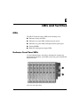
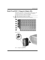
Hardware Features
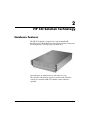
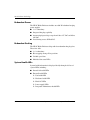
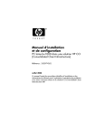
The HP CCI solution is comprised of a rack-mountable HP
BladeSystem PC Blade Enclosure that contains advanced electronics
for managing up to 20 single-processor blade PCs.
HP BladeSystem PC Blade Enclosure with blade PCs (20)
The enclosure and blade PC features described in the following
sections are standard on HP CCI solutions, unless otherwise
specified.
Setup and Installation Guide
www.hp.com
2-1
HP CCI Solution Technology
HP PC Blade Enclosure Standard Features
The HP PC Blade Enclosure features include:
■
3U height and standard 48 cm (19 inch) width
■
Support for up to 20 Blade PCs
■
Interconnect Tray supporting an Interconnect Switch (standard
configuration) or an RJ-45 Patch Panel (optional).
■
Integrated Administrator for local and remote management and
monitoring
■
Redundant power
■
Redundant cooling
■
System health LEDs
Interconnect Switch
The HP PC Blade Enclosure C-GbE Interconnect Switch features
include:
2-2
■
Significant cable reduction - 40 Blade PC NIC connections to
four RJ-45 Gigabit Ethernet uplink connectors.
■
Four sockets supporting optional fiber optic Gigabit Interface
Converter (GBIC)/Small Form-factor Pluggable (SFP) modules.
■
Interconnect tray form factor that fits into blade enclosure
■
Low wattage for maximum power efficiency
■
Compatibility with common core switches
www.hp.com
Setup and Installation Guide
HP CCI Solution Technology
RJ-45 Patch Panel (Optional)
The RJ-45 Patch Panel features:
■
40 port 10/100 RJ-45 connectors
■
1 to 1 mapping between each NIC on the blade PCs to one of the
40 RJ-45 ports on the back of this tray-mounted patch panel
■
Separate Link and Activity LEDs, for each 10/100 port
Integrated Administrator
Integrated Administrator features include:
■
Local and remote access to enclosure and blade PC information
■
Secure Shell, Telnet, and Secure Sockets Layer (SSL) Web access
■
Virtual power and Unit Identification (UID) buttons
■
Access to any blade PC’s remote console
■
Access to any blade PC’s Computer Setup (F10) Utility
■
Support for command line scripting
Setup and Installation Guide
www.hp.com
2-3
HP CCI Solution Technology
Redundant Power
The HP PC Blade Enclosure includes two 600-W redundant hot-plug
power supplies
■
1 + 1 redundancy
■
Integrated hot-plug capability
■
Autosensing input voltage range from 100 to 127 VAC and 200 to
240 VAC
■
Load-sharing across all Blade PCs
Redundant Cooling
The HP PC Blade Enclosure ships with four redundant hot-plug fans.
These fans offer:
■
2 + 2 redundancy
■
Hot-swapping among all fan positions
■
Variable-speed fans
■
Individual fan status LEDs
System Health LEDs
System health information is displayed locally through a full set of
system LEDs, including:
2-4
■
Internal fan health LEDs
■
External health LEDs
❏
Fan health LED
❏
Enclosure health LED
❏
Blade PC LEDs
❏
Power supply LEDs
❏
Integrated Administrator health LED
www.hp.com
Setup and Installation Guide
HP CCI Solution Technology
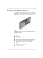
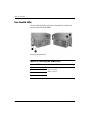
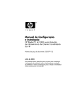
HP BladeSystem bc1500 Blade PC Features
The Blade PC is simple to install, deploy, and service. A Blade PC
that requires out-of-the-rack upgrades, service, or maintenance can be
easily replaced by another Blade PC. The following figure shows a
Blade PC.
Blade PC
A Blade PC supports processor and system architecture technology,
including the following:
■
Processor
■
Memory
■
Mass storage
■
Blade PC status and monitoring
■
Diagnostic adapter (requires optional graphics diagnostic card)
■
Video (connector for a graphics diagnostic card; optional
graphics diagnostic card part number is 346204-001)
■
ROM
■
2 LOM (LAN on mother board)
■
Health and power control
Setup and Installation Guide
www.hp.com
2-5
HP CCI Solution Technology
Processor
Each Blade PC ships with an integrated AMD Athlon™ 64 1500+
with 512KB cache.
Ä
CAUTION: The processor heatsink assembly is integrated into the system
board and cannot be removed.
Memory
The Blade PC supports the following memory features:
■
DDR 333 (2 SODIMM connectors)
For more information, refer to QuickSpecs located on the HP
website: www.hp.com
■
512MB system memory expandable to 2GB with two 1GB
SODIMMs Mass Storage
The Blade PC ships with one ATA hard drive attached with screws.
Blade PC Status and Monitoring
A Blade PC provides the following status and monitoring features:
2-6
■
Blade PC Unit Identification (UID) button/LED
■
Blade PC health LED
■
Blade PC network activity LEDs
■
Hard drive activity LED
■
Power button/LED
■
Diagnostic support through the Computer Setup (F10) Utility, the
Integrated Management Log (IML), and HP Systems Insight
Manager
www.hp.com
Setup and Installation Guide
HP CCI Solution Technology
Diagnostic Adapter and Graphics Diagnostic Card
Each Blade PC has a diagnostic connector. Using the diagnostic
adapter and the graphics diagnostic card (available together as an
after-market option), the following capabilities are available:
■
USB connectivity for two USB devices including diskette drive,
CD-ROM drive, keyboard, and mouse
■
PS/2 connectivity for keyboard and mouse
■
Video connectivity through a standard 15-pin VGA connector
(optional graphics diagnostic card required for video)
■
Serial connectivity for facilitating software maintenance
diagnostic adapter may be represented under System Devices in
✎ The
Device Manager as “Generic Bus.”
Video (optional)
The Blade PC supports video through the diagnostic adapter and the
graphics diagnostic card (available together as an after-market
option). Video features include:
■
Support for SVGA, VGA, and EGA graphics resolution
■
Video is obtained by attaching an optional graphics diagnostic
card to the Blade PC (the optional graphics diagnostic card
supports a resolution of up to 1024 x 768 @ 24 bit color depth)
■
4MB SDRAM video memory
ROM
Blade PC ROM features include:
■
1MB ROM to support system and video
■
Flashbin utility used to upgrade the system ROM
■
Hardware boot block protection
■
Remote ROM flash support
■
Bootable USB diskette drive support
■
Bootable USB CD-ROM drive (limited support)
Setup and Installation Guide
www.hp.com
2-7
HP CCI Solution Technology
NICs
The two embedded NICs on the Blade PC have the following
features:
■
Embedded 10/100-Mbps Broadcom 5705F Fast Ethernet NICs
■
Preboot eXecution Environment (PXE) support (first NIC only)
■
Auto-negotiation of 10/100-Mbps link speeds
■
Full-duplex Ethernet support
■
Teaming for network fault tolerance or load balancing (also
known as port bonding or trunking)
Software Deployment and Management Features
HP offers an extensive set of features and optional tools to support
effective software deployment and management. See Chapter 5,
“Deployment and Management,” for more detailed descriptions of the
following:
■
HP PC Blade Enclosure Integrated Administrator
The HP PC Blade Enclosure Integrated Administrator is a
centralized management and monitoring system for the HP PC
BL Enclosure and blade PCs. The Integrated Administrator acts
as a combination terminal server and remote power controller,
enabling out-of-band, secure, serial console connections to all
Blade PCs in the enclosure.
■
Computer Setup (F10) Utility
Computer Setup performs a wide range of configuration activities
and provides access to numerous settings, including those for
system devices, security, storage, and boot order.
■
HP Rapid Deployment Pack
HP Rapid Deployment Pack features include:
2-8
❏
A graphical deployment console which provides intuitive
drag-and-drop events, such as scripts and images, to deploy
the operating systems and applications on any combination of
Blade PCs installed in the enclosures
❏
Simultaneous deployment of multiple Blade PCs
www.hp.com
Setup and Installation Guide
HP CCI Solution Technology
❏
Advanced features that can detect and display Blade PCs
based on their physical rack, enclosure, and bay locations
❏
The ability to set the deployment console to automatically
install pre-defined configurations on newly-installed Blade
PCs
For more information about HP Rapid Deployment Pack, refer to
your authorized reseller, the Rapid Deployment CD that ships
with the enclosure, or visit the HP website: www.hp.com
■
HP Systems Insight Manager
HP Systems Insight Manager provides in-depth fault, inventory,
and configuration management of HP server platforms (including
hundreds of Blade PCs) from a single console.
■
Automatic System Recovery-2 (ASR-2)
ASR-2 is a diagnostic/recovery feature that automatically restarts
the Blade PC in the event of a critical operating system failure.
■
Enclosure Self Recovery (ESR)
ESR, similar to ASR-2, is a self-monitoring reliability feature of
the Integrated Administrator. If the Integrated Administrator does
not boot or hangs during operation, ESR automatically resets the
Integrated Administrator for an attempted self-recovery. The
Blade PCs and interconnect tray are not affected by ESR.
■
Integrated Management Log (IML)
The IML provides a detailed log of key system events. This log,
which also monitors the health log, is accessible by utilities,
including HP Systems Insight Manager.
■
Flashbin
Flashbin enables you to upgrade the firmware (BIOS) with
system or option Flashbin utilities.
■
Online ROM Flash
Using the Smart Components for Remote ROM Flash with the
Remote Deployment Utility (RDU) console application, Remote
ROM Flash enables you to upgrade the firmware (BIOS) from a
remote location.
■
Setup and Installation Guide
HP PC Blade Enclosure C-GbE Interconnect Switch
www.hp.com
2-9
HP CCI Solution Technology
The interconnect switch concentrates the forty 10/100 Ethernet
Blade PC network connections into four RJ-45 Gigabit Ethernet
uplink connectors. Each uplink can communicate with all 40
network connections; thus, only one to all four of these
connectors may be used providing up to a 40-to-1 reduction in the
number of network cables connected to the enclosure. The
interconnect switch is compatible with industry standards and is
fully pre-configured for immediate use.
For more information about these tools and utilities, see Chapter 5,
“Deployment and Management.”
Diagnostic Features
The hardware, software, and firmware diagnostic tools that are
available include:
2-10
■
HP PC Blade Enclosure Integrated Administrator
■
Diagnostic adapter for local Blade PC access (requires optional
graphics diagnostic card)
■
Optional graphics diagnostic card
■
HP Systems Insight Manager
■
Power-On Self Test (POST)
■
Diagnostics Utility
■
Flashbin
■
Health monitoring LEDs
www.hp.com
Setup and Installation Guide
3
Planning the Installation
Optimum Environment
For maximum performance and availability from your HP CCI
solution, be sure that your operating environment meets the required
specifications for the following:
■
Floor strength
■
Space
■
Power
■
Electrical grounding
■
Temperature
■
Airflow
For detailed information on these requirements, refer to the HP PC
Blade Enclosure System Overview and Planning white paper at the
HP website: www.hp.com
Rack Warnings and Cautions
Before installing your rack, observe the following warnings and
cautions:
Å
WARNING: To reduce the risk of personal injury or equipment damage,
be sure that:
• The rack is adequately stabilized before installing or removing a
component.
• Only one component is extended at a time.
• The leveling jacks are extended to the floor.
• The full weight of the rack rests on the leveling jacks.
• The stabilizers are attached to the rack for single-rack installation.
Setup and Installation Guide
www.hp.com
3-1
Planning the Installation
Å
WARNING: To reduce the risk of personal injury or equipment damage,
AT LEAST two people are needed to safely unload the rack from the pallet.
An empty 42U rack can weigh as much as 115 kg (253 lb), can stand
more than 2.1 m (7 ft) tall, and may become unstable when being moved
on its casters.
Never stand in front of the rack when it is rolling down the ramp from the
pallet; always handle the rack from both sides.
Å
WARNING: When installing the enclosure in a Telco rack, be sure that
the rack frame is adequately secured to the top and bottom of the building
structure.
Ä
CAUTION: When using a Compaq branded 7000 Series rack, you must
install the high airflow rack door insert [P/N 327281-B21 (for 42U rack)
and P/N 157847-B21 (for 22U rack)] to provide proper front-to-back
airflow and cooling and to prevent damage to the equipment.
Ä
CAUTION: If an HP or third-party rack is used, observe the following
additional requirements to ensure adequate airflow and to prevent
damage to the equipment:
• Front and rear doors: If the 42U rack includes closing front and rear doors,
you must allow 5,350 sq cm (830 square inches) of holes evenly
distributed from top to bottom to permit adequate airflow (equivalent to the
required 64 percent open area for ventilation).
• Side: The clearance between the installed rack component and the side
panels of the rack must be a minimum of 7 cm (2.75 inches).
Ä
3-2
CAUTION: The PC Blade Enclosure is shipped without blanking panels.
Always use blanking panels (available as an option) to fill all remaining
empty front panel U-spaces in the rack. This arrangement ensures proper
airflow. Using a rack without blanking panels results in improper cooling
that can lead to thermal damage.
www.hp.com
Setup and Installation Guide
Planning the Installation
HP PC Blade Enclosure Warnings and Cautions
Before installing the HP PC Blade Enclosure, carefully review the
following warnings and cautions:
Å
WARNING: To reduce the risk of personal injury or damage to
equipment, heed all warnings and cautions throughout the installation
instructions.
Å
WARNING: A risk of injury or damage to the equipment from
hazardous energy is present. The access door provides access to
hazardous energy circuits. The door should remain locked during normal
operation or troubleshooting, or the system should be installed in a
controlled access location where only qualified personnel have access to
the system.
Å
WARNING: To reduce the risk of electrical shock or damage to the
equipment:
• Only enter or perform service on specific parts of the HP CCI solution as
instructed in the user documentation.
• Do not disable the power cord grounding plugs. The grounding plugs are
an important safety feature.
• Plug both power cords into a grounded (earthed) electrical outlet that is
easily accessible at all times.
• Unplug the power cords from the power supplies to disconnect power to
the enclosure.
Å
WARNING: To reduce the risk of personal injury from hot surfaces,
allow the internal system components to cool before touching them.
Setup and Installation Guide
www.hp.com
3-3
Planning the Installation
Å
WARNING: The HP PC Blade Enclosure is very heavy. To reduce the risk
of personal injury or damage to the equipment:
• Observe local occupational health and safety requirements and guidelines
for manual material handling.
• Remove Blade PCs and power supplies from the enclosures before
installing or removing the enclosures.
• Use caution and get help to lift and stabilize an enclosure during
installation or removal, especially when the enclosure is not fastened to the
rack. If the enclosure is being loaded into the rack above chest level, a
third person MUST assist with aligning the enclosure with the rails while the
other two people support the weight of the enclosure.
3-4
Å
WARNING: The HP PC Blade Enclosure has two power cords for
redundant AC power sources. If it is necessary to remove power for
servicing, disconnect all power by removing both power supply cords from
either the wall or the AC connectors on the rear of the enclosure.
Ä
CAUTION: When servicing non-hot-plug components, you must power
down the Blade PCs and/or the enclosure and Blade PCs. However, it
may be necessary to leave the Blade PCs powered up when performing
other operations, such as hot-plug replacement or troubleshooting.
Ä
CAUTION: Protect your equipment from power fluctuations and
temporary interruptions with a regulating UPS device. This device protects
the hardware from damage caused by power surges and voltage spikes
and keeps the system in operation during a power failure.
Ä
CAUTION: Always be sure that equipment is properly grounded before
beginning any installation procedure. Electrostatic discharge resulting
from improper grounding can damage electronic components. For more
information, see Appendix B, “Electrostatic Discharge.”
Ä
CAUTION: Do not remove a power supply without a replacement ready
to install. A failed power supply must remain in the system for proper
airflow to prevent overheating while the system is operating.
www.hp.com
Setup and Installation Guide
Planning the Installation
Preparing for Software Deployment
To prepare for software deployment, you must first set up HP Rapid
Deployment Pack or another deployment method. These deployment
methods are discussed in Chapter 5, “Deployment and Management.”
HP Rapid Deployment Pack
To deploy your Blade PCs using HP Rapid Deployment Pack, be sure
that you have a DHCP server for IP address assignment, a deployment
server (can be the same system as the DHCP server), and the Rapid
Deployment CD included with your enclosure.
Alternate Deployment Method
If you are not using HP Rapid Deployment Pack, use your preferred
deployment infrastructure. Blade PCs have a PXE-enabled NIC (the
first NIC only) and support bootable USB CD-ROM and USB
diskette drives (attached via the diagnostic adapter).
Shipping Contents
IMPORTANT: All of the rack-mounting hardware necessary for installing
the HP PC Blade Enclosure into an HP, Compaq branded, or third-party
rack is included with your enclosure. For Telco racks, a separate option kit
with Telco rack-mounting hardware is available.
Setup and Installation Guide
www.hp.com
3-5
Planning the Installation
Blade Enclosure
The HP PC Blade Enclosure ships with the following:
■
Two redundant hot-plug power supplies and power cords
■
C-GbE Interconnect Switch with Integrated Administrator
■
Four redundant hot-plug fans
■
Documentation CD.
■
Rack-mounting hardware for HP, Compaq branded, and
third-party racks
Ä
CAUTION: Always install either a Blade PC or a Blade PC blank in each
Blade PC bay to maintain proper airflow and cooling. Improper airflow
can lead to thermal damage.
Ä
CAUTION: Do not remove a power supply without a replacement ready
to install. A failed power supply must remain in the system for proper
airflow to prevent overheating while the system is operating.
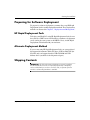
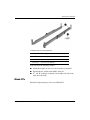
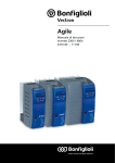
Rack-Mounting Hardware
The following figure and table show the standard rack-mounting
hardware (for HP, Compaq-branded, and third-party racks) that ships
with the HP PC Blade Enclosure.
Ä
CAUTION: Do not ship the blade PCs and enclosure while inside the
rack without first installing the HP PC Blade Enclosure Shipping Bracket
(part number PH555A). Failure to use the shipping bracket may cause
damage to the blade PC and/or enclosure, thereby voiding the warranty.
Refer to the documentation in the option kit for more information.
IMPORTANT: All of the rack-mounting hardware necessary for installing
the HP PC Blade Enclosure into an HP, Compaq branded, or third-party
rack is included with your enclosure. For Telco racks, a separate option kit
with Telco rack-mounting hardware is available.
3-6
www.hp.com
Setup and Installation Guide
Planning the Installation
Standard rack-mounting hardware
Item
Description
1
Rack rails (2, left and right)
2
Bag of screws
Not shown
Enclosure rack template
Rack rails have the following features:
■
Adjustable depth of 61 cm to 91 cm (24 inches to 36 inches)
■
Depth indicator, visible in the middle of the rail
■
"L" and "R" markings to identify left and right rack rails (from
the front of the rack)
Blade PCs
Blade PCs ship in packages of one or ten Blade PCs.
Setup and Installation Guide
www.hp.com
3-7
Planning the Installation
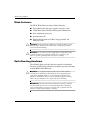
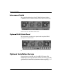
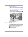
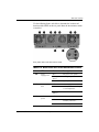
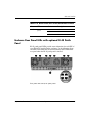
Interconnect Switch
The standard configuration of the PC Blade Enclosure includes a
C-GbE Interconnect switch installed into the back of the enclosure.
Rear of enclosure with Interconnect switch
Optional RJ-45 Patch Panel
The interconnect switch may be replaced with an optional RJ-45
patch panel as shown below.
Rear of enclosure with optional RJ-45 patch panel installed
Optional Installation Service
You may choose to have HP install your HP CCI solution. This
method helps ensure top performance from the start and is especially
valuable for business-critical environments. Contact your HP account
representative to obtain more detailed information and pricing.
3-8
www.hp.com
Setup and Installation Guide
4
Installing and Cabling the HP CCI
Solution
This chapter contains the following procedures:
■
Measuring with the rack template
■
Installing the rack rails
■
Installing the enclosure into the rack
■
Cabling the HP CCI solution
❏
Identifying interconnect tray connectors
❏
Cabling the enclosure
■
Powering up the HP CCI solution
■
Powering down the HP CCI solution
❏
Powering down a Blade PC
❏
Powering down the enclosure
■
Installing a Blade PC
■
Removing a Blade PC
■
Installing additional memory
■
Attaching the diagnostic adapter and optional graphics diagnostic
card
Setup and Installation Guide
www.hp.com
4-1
Installing and Cabling the HP CCI Solution
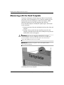
Measuring with the Rack Template
Using the rack template, identify the proper holes for inserting the
tabs on the vertical rack supports. Use a pencil to mark the top and
bottom edges for the rack supports on the rack template, which
identify the position for the rails supporting the enclosure.
To use the rack template to identify the required space and location
for the enclosure:
1. Stand at the front of the rack and identify the front side of the rack
template.
2. Starting at the top of the last item installed, secure the rack
template against the front of the rack by sliding the two push tabs
into the holes in the rack supports.
Å
WARNING: Racks must be adequately stabilized before and after
product installation. If you are installing an enclosure into an empty rack,
you must install the enclosure at the bottom of the rack and work your
way up with additional enclosures as needed.
IMPORTANT: Match the hole pattern on the rack template with the
holes in the rack supports.
Measuring with the rack template
4-2
www.hp.com
Setup and Installation Guide
Installing and Cabling the HP CCI Solution
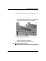
3. Align the rack template so that its sides are square with the sides
of the rack.
IMPORTANT: Tick marks on the rack supports help you to maintain
proper alignment of the rack template.
4. Use a pencil to mark an “M” at the locations on the rack where
the rack rails are to be inserted 1.
5. On the rack, mark the top and bottom edges of the rack template
to help align the rack template for the next enclosure 2.
Marking the rack for enclosure installation
6. Remove the rack template from the front of the rack and move to
the back of the rack.
7. Identify the back side of the rack template.
8. Repeat steps 2 through 5 for the back of the rack.
✎ Store the rack template for future use.
Setup and Installation Guide
www.hp.com
4-3
Installing and Cabling the HP CCI Solution
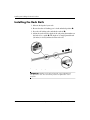
Installing the Rack Rails
1. Measure the depth of your rack.
2. Be sure that the rail locking gear is in the unlocked position 1.
3. Press the rail locking tab to unlock the rack rail 2.
4. Adjust the rack rail to the depth of the rack using the numbers on
the rack rail as a guide 3. The depth of a Compaq branded rack
(29 inches) is clearly indicated on the rack rails.
Unlocking and adjusting a rack rail
IMPORTANT: Numbers on the rack rail provide a gross adjustment of
the depth of the rack. The rack rail may need to be tightened to ensure
proper fit.
4-4
www.hp.com
Setup and Installation Guide
Installing and Cabling the HP CCI Solution
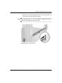
5. Insert the rear of the right rack rail into the rack at the marks you
made when measuring with the template.
rack rails feature “L” and “R” markings to identify the left and
✎ The
right rack rails (from the front of the rack).
Inserting the rear of the rack rail
Setup and Installation Guide
www.hp.com
4-5
Installing and Cabling the HP CCI Solution
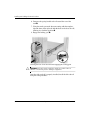
6. Compress the spring-loaded rack rail toward the rear of the
rack 1.
7. Using the marks you made when measuring with the template,
align the front of the right rail with the holes and release the rail,
allowing it to lock into position 2.
8. Engage the locking gear 3.
Inserting the front of the rack rail and engaging the locking gear
Ä
CAUTION: Rack rails must be installed as tightly as possible. Failure to
obtain a correct fit may result in damage to equipment.
Once the right rack rail is properly installed, install the left rack rail
using the same procedure.
4-6
www.hp.com
Setup and Installation Guide
Installing and Cabling the HP CCI Solution
Installing the Enclosure into the Rack
The enclosure ships with two different sizes of thumbscrews:
■
Size 10-32 thumbscrews with white hexagonal washers, which
are compatible with Compaq-branded racks and some HP and
third-party racks
■
Size M6 thumbscrews with black hexagonal washers, which are
compatible with some third-party racks that require metric sizes
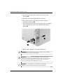
To replace a thumbscrew:
1. Pull the thumbscrew outward 1.
2. Unscrew the thumbscrew 2 while holding on to the hexagonal
washer.
3. Remove the thumbscrew and hexagonal washer 3.
Removing a thumbscrew and hexagonal washer
Setup and Installation Guide
www.hp.com
4-7
Installing and Cabling the HP CCI Solution
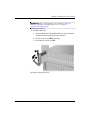
4. Place the hexagonal washer at the back of the hole in the
enclosure 1.
5. Insert the screw through the hole in the enclosure.
6. Press the head of the screw inward so that the spring is
completely compressed 2.
7. Screw the hexagonal washer onto the shaft of the screw until it
passes all the threads and is secure within the thumbscrew
housing 3.
Replacing a thumbscrew, spring, and hexagonal washer
8. Repeat steps 1 through 7 for the other thumbscrew.
4-8
Å
WARNING: Remove the two hot-plug power supplies before installing
the enclosure into the rack to reduce weight.
Å
WARNING: At least two people must lift the enclosure into the rack
together. If the enclosure is loaded into the rack above chest level, a third
person must assist with aligning the enclosure with the rails while the
other two people support the weight of the enclosure.
Ä
CAUTION: Do not remove the enclosure from the rack by the
thumbscrews. Use the handles located above the thumbscrews.
www.hp.com
Setup and Installation Guide
Installing and Cabling the HP CCI Solution
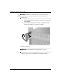
To load the enclosure into the rack:
1. Refer to the “Measuring with the Rack Template” section in this
chapter.
2. Stand at the front of the rack.
3. Align the bottom of the enclosure with the top of the rack rails.
4. Slide the enclosure fully into the rack 1.
5. Tighten the thumbscrews to secure the enclosure in the rack 2.
Installing the enclosure into the rack
Cabling the HP CCI Solution
An HP CCI solution requires no internal cabling. External cabling is
achieved through the interconnect switch installed in your solution.
The procedure for cabling an enclosure consists of the following
steps:
■
Identifying the interconnect switch connectors
■
Cabling the blade enclosure
Setup and Installation Guide
www.hp.com
4-9
Installing and Cabling the HP CCI Solution
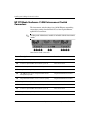
HP PC Blade Enclosure C-GbE Interconnect Switch
Connectors
The interconnect switch reduces forty 10/100 Ethernet networking
connections coming from the Blade PCs to four Gigabit Ethernet
uplink RJ-45 connectors.
Integrated Administrator module is included with the interconnect
✎ An
switch.
Interconnect switch connectors
Item
Description
Location
1
Gigabit Ethernet jack for port 43
Interconnect switch
2
Socket for optional GBIC SFP module for port 43
Interconnect switch
3
Socket for optional GBIC SFP module for port 44
Interconnect switch
4
Gigabit Ethernet jack for port 44
Interconnect switch
5
10/100 Ethernet jack for Integrated Administrator
management port 42
Integrated Administrator module
6
Integrated Administrator console connector (serial)
Integrated Administrator module
7
Gigabit Ethernet jack for port 45
Interconnect switch
8
Socket for optional GBIC SFP module for port 45
Interconnect switch
9
Socket for optional GBIC SFP module for port 46
Interconnect switch
-
Gigabit Ethernet jack for port 46
Interconnect switch
4-10
www.hp.com
Setup and Installation Guide
Installing and Cabling the HP CCI Solution
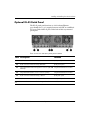
Optional RJ-45 Patch Panel
The RJ-45 patch panel functions as a fault tolerant Ethernet
pass-through for a 1 to 1 mapping between each NIC on each Blade
PC to one of the 40 RJ-45 ports on the back of this tray-mounted
patch panel.
Rear of enclosure with RJ-45 patch panel installed
Item Description
Location
1
RJ-45 connector for Blade PC bay 20 NIC A
RJ-45 patch panel
2
RJ-45 connector for Blade PC bay 20 NIC B
RJ-45 patch panel
3
Integrated Administrator management connector (10/100 Integrated Administrator module
Ethernet)*
4
Integrated Administrator console connector (serial)*
Integrated Administrator module
5
RJ-45 connector for Blade PC bay 1 NIC B
RJ-45 patch panel
6
RJ-45 connector for Blade PC bay 1 NIC A
RJ-45 patch panel
✎
*These items denote connectors for the Integrated Administrator module.
Setup and Installation Guide
www.hp.com
4-11
Installing and Cabling the HP CCI Solution
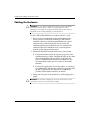
Cabling the Enclosure
Ä
CAUTION: Do not connect external devices to the enclosure link (RJ-45)
connectors unless the device is listed as a supported device on the
Quickspecs. Connecting an unsupported external device to the enclosure
link (RJ-45) connectors may damage your external device.
To cable a HP PC Blade Enclosure already installed in a rack:
1. For accessing and configuring the Integrated Administrator
locally, connect a client device (running VT-100 terminal
emulation software) to the Integrated Administrator console
connector using a null-modem cable. For accessing and
configuring the Integrated Administrator over your network,
connect the Integrated Administrator to your management
network via the management connector.
2. Connect the Blade PC network connectors to your network
❏
For the interconnect switch, be sure that at least one of the
uplink connectors is cabled. Any Blade PC NIC can be routed
to any of the uplink connectors. However, because only
NIC A is PXE-enabled by default on each Blade PC, it is
recommended that either port 45 or 46 be used for PXE
functions.
❏
For the RJ-45 patch panel, be sure that cables are connected
for each Blade PC you intend to install in the enclosure. Only
the NIC 1 (bottom) RJ-45 connector for each Blade PC
provides PXE-enabled connectivity by default.
3. Connect the AC power cord (provided) to each hot-plug power
supply.
Ä
4-12
CAUTION: The enclosure will power up as soon as an AC power cord is
connected to a power source and a power supply.
www.hp.com
Setup and Installation Guide
Installing and Cabling the HP CCI Solution
4. Bundle network and power cables together and route them to the
outer edge of the rack.
Cabling the solution with the interconnect switch
Cabling the solution with the RJ-45 patch panel
Setup and Installation Guide
www.hp.com
4-13
Installing and Cabling the HP CCI Solution
IMPORTANT: Be sure to route the cables for your enclosure in a manner
that provides rapid, easy access to the console connector for a local client
device, such as a laptop computer. Also be sure to route the cables so
they do not block or restrict airflow from any of the fan openings.
5. Repeat steps 1 through 4 for each Blade PC enclosure you have
installed.
Null-Modem Cable
If you are cabling a serial device such as a laptop computer to the
console connector on the Integrated Administrator, be sure to use a
null-modem cable and not a straight-through cable. The following
table defines the wiring of a null-modem cable.
Cable Pinout for a Null-Modem Cable
4-14
Signal Name
EM PIN
DB-9 PIN
DB-25 PIN
TxD
3
2
3
RxD
2
3
2
RTS
7
8
5
CTS
8
7
4
GND
5
5
7
DSR
6
4
20
CD
1
4
20
DTR
4
1&6
6&8
TxD
3
2
3
www.hp.com
Setup and Installation Guide
Installing and Cabling the HP CCI Solution
Installing a Blade PC
Ä
CAUTION: Electrostatic discharge can damage electronic components.
Properly ground yourself before beginning any installation procedure. See
Appendix B, “Electrostatic Discharge,” for more information.
To install a Blade PC:
1. Determine your hardware configuration and deployment process.
See Chapter 5, “Deployment and Management.”
2. Install or upgrade memory before installing Blade PCs into an
enclosure. See the “Installing Additional Memory” section in this
chapter.
Ä
CAUTION: The HP PC Blade Enclosure is shipped without Blade PC
blanks. Always populate the Blade PC bays with either a Blade PC or a
Blade PC blank (available as an option). Proper airflow can only be
maintained when the bays are populated. Unpopulated bays can lead to
improper cooling and thermal damage.
Setup and Installation Guide
www.hp.com
4-15
Installing and Cabling the HP CCI Solution
3. If Blade PC blanks have been installed, remove the Blade PC
blank:
a. Press the ejector tabs on the Blade PC blank 1.
b. Slide the Blade PC blank out of the bay 2.
Removing a single-bay Blade PC blank
Removing a five-bay Blade PC blank
✎ Store the Blade PC blank for future use.
4-16
www.hp.com
Setup and Installation Guide
Installing and Cabling the HP CCI Solution
IMPORTANT: Before installing Blade PCs for the first time, define your
hardware configuration and deployment process. See Chapter 5,
“Deployment and Management.”
4. Install the Blade PC:
a. Align the Blade PC with the Blade PC bay on the enclosure
and slide the blade partially into the enclosure.
b. Press the release latch 1 on the blade.
c. Pull down the ejector lever 2.
Opening the blade eject lever
Setup and Installation Guide
www.hp.com
4-17
Installing and Cabling the HP CCI Solution
Ä
CAUTION: The Blade PC is keyed to fit only one way in the bay. If the
Blade PC does not slide easily into the bay, be sure that the Blade PC is
oriented properly.
d. Slide the Blade PC inward until the ejector lever engages the
enclosure 1.
e. Close the ejector lever until you hear an audible click that
indicates the Blade PC is properly seated 2.
Installing a Blade PC
IMPORTANT: Install a Blade PC for each of the blanks you have
removed.
5. Repeat steps 2 to 4 for each Blade PC you wish to install.
4-18
www.hp.com
Setup and Installation Guide
Installing and Cabling the HP CCI Solution
Powering Up the HP CCI Solution
As soon as you connect an AC power cord to a hot-plug power supply
on the rear panel, the enclosure powers up. All Blade PCs already
installed in the enclosure also power up one at a time in
approximately one-second intervals. Plug in the second power supply
for redundancy.
A Blade PC installed into a powered enclosure will immediately
power up.
Powering Down the HP CCI Solution
You can power down one or more Blade PCs or the entire enclosure.
Powering Down a Blade PC
To power down a Blade PC:
1. Be sure that the Blade PC is not active.
For specific information about Blade PC LEDs, see Appendix E,
“LEDs and Switches.”
2. If the Blade PC is active, notify users and stop applications as
necessary.
3. Shut down the operating system. This may shut off the Blade PC
power.
Setup and Installation Guide
www.hp.com
4-19
Installing and Cabling the HP CCI Solution
4. If the Blade PC still has power, power down the Blade PC by
either:
❏
Using the Integrated Administrator
or
❏
Pressing the power button on the front of the Blade PC
IMPORTANT: Refer to the HP PC Blade Enclosure Integrated
Administrator User Guide to power down the Blade PC using the
Integrated Administrator.
Powering down the Blade PC
To perform an emergency shut down of a Blade PC, press and hold
the blade power button for four seconds.
Ä
4-20
CAUTION: Performing an emergency shutdown on a Blade PC may
result in the loss of any unsaved data.
www.hp.com
Setup and Installation Guide
Installing and Cabling the HP CCI Solution
Powering Down the Enclosure
To perform a graceful shutdown of the enclosure and all the Blade
PCs, press the enclosure power button. If your operating system is
Microsoft Windows XP, the enclosure automatically performs a
graceful shutdown of all Blade PCs, and then removes power from the
enclosure.
To perform an emergency shut down of the enclosure and all Blade
PCs at the same time, press and hold the enclosure power button for
four seconds.
Ä
CAUTION: Performing an emergency shutdown on the enclosure may
result in the loss of any unsaved data on all Blade PCs.
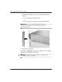
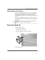
Removing a Blade PC
To remove a Blade PC:
1. Press the release latch 1.
2. Pull down the ejector lever 2.
3. Remove the Blade PC from the enclosure 3.
Removing a Blade PC
Setup and Installation Guide
www.hp.com
4-21
Installing and Cabling the HP CCI Solution
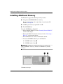
Installing Additional Memory
The Blade PCs support the following memory features:
■
Unregistered SODIMM DDR 333 memory
For more information, refer to QuickSpecs located on the HP
website: www.hp.com
■
512MB system memory expandable to 2GB
■
Two SODIMM slots
To install SODIMMs on a Blade PC:
1. Power down the Blade PC. See the “Powering Down a Blade PC”
section in this chapter.
2. Remove the Blade PC from the enclosure. See the “Removing a
Blade PC” section in this chapter.
3. Place the Blade PC on a level, nonconductive surface.
4. Locate the SODIMM socket keys on the Blade PC:
❏
SODIMM socket 1 keys 1
❏
SODIMM socket 2 keys 2
IMPORTANT: SODIMMs are installed inverted from one another. If the
labels on SODIMM 1 are face-up, the labels on SODIMM 2 are probably
face-down.
SODIMM socket keys
4-22
www.hp.com
Setup and Installation Guide
Installing and Cabling the HP CCI Solution
IMPORTANT: Step 5 applies only when you wish to upgrade
SODIMMs.
5. Remove the existing SODIMM:
a. Release the latches on each side of the SODIMM slot 1 1.
b. Remove the SODIMM from the Blade PC 2.
Removing an SODIMM
Setup and Installation Guide
www.hp.com
4-23
Installing and Cabling the HP CCI Solution
6. Install SODIMM 1:
a. Match the notch on the SODIMM with the tab on the
SODIMM socket and insert the SODIMM into the socket at a
slight angle 1.
b. Press the SODIMM down towards the board, ensuring that it
is fully seated and the latches snap into place 2.
Installing an SODIMM
7. Repeat step 6 to install a second SODIMM into SODIMM slot 2.
4-24
www.hp.com
Setup and Installation Guide
Installing and Cabling the HP CCI Solution
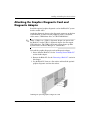
Attaching the Graphics Diagnostic Card and
Diagnostic Adapter
Install the optional graphics diagnostic card on the Blade PC system
board to enable video.
Attach the diagnostic adapter to the diagnostic connector on the front
of the Blade PC in order to attach peripherals such as a keyboard,
video, mouse, USB diskette drive, or USB CD-ROM drive.
a USB 2.0 or a USB 1.1 diagnostic adapter can operate with
✎ Either
the Blade PC, but the USB 1.1 diagnostic adapter does not support
USB 2.0 devices. The USB 2.0 diagnostic adapter shows up under
System Devices in Device Manager as “Generic Bus.”
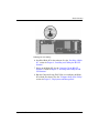
To install the graphics diagnostic card and diagnostic adapter:
1. Power down the Blade PC. See the “Powering Down a Blade PC”
section in this chapter.
2. Remove the Blade PC. See the “Removing a Blade PC” section in
this chapter.
3. Lay the Blade PC down on a flat surface and install the optional
graphics diagnostic card into the sockets.
Installing the optional graphics diagnostic card
Setup and Installation Guide
www.hp.com
4-25
Installing and Cabling the HP CCI Solution
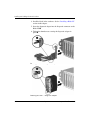
4. Install the blade in the enclosure. See the “Installing a Blade PC”
section in this chapter.
5. Insert the diagnostic adapter into the diagnostic connector on the
Blade PC 1.
6. Tighten the thumbscrews securing the diagnostic adapter in
place 2.
Attaching the USB 2.0 diagnostic adapter
Attaching the USB 1.1 diagnostic adapter
4-26
www.hp.com
Setup and Installation Guide
Installing and Cabling the HP CCI Solution
Use the following figure and table to identify connectors on the
USB 2.0 diagnostic adapter.
Connectors on the USB 2.0 diagnostic adapter
Item
Setup and Installation Guide
Description
1
PS/2 Mouse connector
2
PS/2 Keyboard connector
3
Serial connector
4
Video connector
5
USB 2.0 #1
6
USB 2.0 #2
www.hp.com
4-27
Installing and Cabling the HP CCI Solution
Use the following figure and table to identify connectors on the
USB 1.1 diagnostic adapter.
Connectors on the USB 1.1 diagnostic adapter
Item
4-28
Description
1
PS/2 Mouse connector
2
USB 1.1 #2
3
Serial connector
4
PS/2 Keyboard connector
5
USB 1.1 #1
6
Video connector
www.hp.com
Setup and Installation Guide
5
Deployment and Management
This chapter provides the following information:
■
■
Setup and Installation Guide
An overview of available methods for deploying software on
Blade PCs
❏
Automated deployment using HP Rapid Deployment Pack
❏
Alternate deployment methods
❏
Diagnostic adapter and optional graphics diagnostic card
A description of the configuration software and utilities
supported by the HP CCI solution
❏
Supported operating systems
❏
Computer Setup (F10) Utility
❏
Flashbin Utility
❏
Remote ROM Flash
❏
HP PC Blade Enclosure Integrated Administrator
❏
HP Systems Insight Manager
❏
HP PC Blade Enclosure C-GbE Interconnect Switch
management tools and utilities
www.hp.com
5-1
Deployment and Management
Blade PC Deployment Options
The Blade PCs are designed for rapid deployment and are ideally
suited for headless (unattended), network-based software installation
and configuration. HP Rapid Deployment Pack is the optimum choice
for Blade PCs and facilitates the configuration of a few or hundreds
of blades from an easy-to-use, remote-based graphical deployment
console. The PXE-enabled NIC (only the first NIC) and support for
bootable USB diskette and USB CD-ROM drives on the Blade PC
also facilitate the use of other deployment methods.
Automated Deployment Using HP Rapid Deployment
Pack
HP Rapid Deployment Pack (RDP) integrates two powerful products:
Altiris Deployment Solution and the ProLiant Integration Module.
The RDP console’s graphical interface provides intuitive
drag-and-drop events, such as scripts and images, for deploying
operating systems and applications to multiple Blade PCs
simultaneously. HP Rapid Deployment Pack also has advanced
features that can detect and display Blade PCs based on their physical
rack, enclosure, and bay locations. You can set the deployment
console to automatically install pre-defined configurations on newly
installed Blade PCs.
For more information about HP Rapid Deployment Pack, refer to
your authorized reseller, the Rapid Deployment CD that ships with
your enclosure, or visit the following website:
www.hp.com/servers/rdp
Alternate Deployment Methods
Blade PCs have a PXE-enabled NIC (the first NIC only) and support
bootable USB diskette and CD-ROM drives, as well as a keyboard,
video, and a mouse attached via the diagnostic adapter. These
features enable you to use your own network-based or local, attended
deployment methods for booting and installing software onto Blade
PCs.
5-2
www.hp.com
Setup and Installation Guide
Deployment and Management
Diagnostic Adapter and Optional Graphics Diagnostic
Card
The diagnostic adapter and the optional graphics diagnostic card
enable local health monitoring and management by enabling you to
attach peripheral devices directly to a Blade PC. Using the diagnostic
adapter and optional graphics diagnostic card, you can:
■
View Blade PC event messages (See the “Blade PC Event
Messages” section in this chapter.)
■
Flash the Blade PC ROM (See the “Flashing the Blade PC ROM”
section in this chapter.)
■
View software information during deployment
For instructions on how to attach the diagnostic adapter and optional
graphics diagnostic card, see Chapter 4, “Installing and Cabling the
HP CCI Solution.”
IMPORTANT: You can hot-plug peripheral devices using the diagnostic
adapter if the devices support hot-plug capability.
Setup and Installation Guide
www.hp.com
5-3
Deployment and Management
Blade PC Features and Supported Software
Configuring your Blade PC includes installing an operating system,
applications, and optimized drivers.
HP Rapid Deployment Pack enables you to auto-detect and configure
your hardware and to install optimized drivers.
Supported Operating Systems
Blade PCs support Microsoft Windows XP Professional SP1a or
later.
Computer Setup (F10) Utility
The Computer Setup (F10) Utility performs configuration activities
and enables you to view Blade PC configuration information. The
Blade PC comes pre-configured and does not require interaction with
Computer Setup, unless you would like to change the default settings.
The following table contains the Computer Setup menu options.
To access the Computer Setup (F10) Utility, install the optional
graphics diagnostic card and the diagnostic adapter along with a
keyboard and monitor on the blade you want to access and press the
F10 key during boot.
For remote console users, you can access the Computer Setup (F10)
Utility through the Integrated Administrator. Reboot the blade
through the Integrated Administrator and press the Esc key then press
the 0 (zero) key. Refer to the HP PC Blade Enclosure Integrated
Administrator User Guide for details.
function keys in remote console are accessed by pressing Esc
✎ The
then the numbers 1 through 0 for F1 through F10. F11 is accessed
by pressing Esc then ! and F12 is accessed by pressing Esc then @.
Blade PC configuration information can also be managed remotely
using System Software Manager (SSM). For more information, refer
to the following website: www.hp.com/go/ssm
5-4
www.hp.com
Setup and Installation Guide
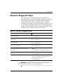
Deployment and Management
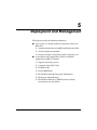
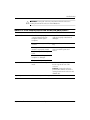
Computer Setup (F10) Utility
Heading
Option
Description
File
System Information
Lists:
• Product Name
• Processor Type
• Processor Stepping
• Cache Size (L1/L2) (dual core processors
have this listed twice)
• HyperTransport™ Speed
• Memory Size
• Integrated MAC (address for embedded,
enabled NIC A)
• Integrated MAC 2 (address for
embedded, enabled NIC B)
• System BIOS (includes family name
and version)
• Blade Serial Number
• Asset Tracking Number
• Rack Name
• Enclosure Name
• Enclosure Model
• Enclosure Serial Number
About
Displays copyright notice.
Set Time and Date
Allows you to set system time and date.
for specific Computer Setup options may vary depending on the hardware
✎ Support
configuration.
Setup and Installation Guide
www.hp.com
5-5
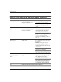
Deployment and Management
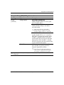
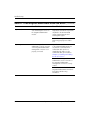
Computer Setup (F10) Utility (Continued)
Heading
Option
Description
File
(continued)
Replicated Setup
Save to Removable Media
Saves system configuration, including CMOS,
to a formatted 1.44-MB diskette, a USB flash
media device, or a diskette-like device (a
storage device set to emulate a diskette drive).
Restore from Removable Media
Restores system configuration from a diskette,
a USB flash media device, or a diskette-like
device.
Storage
Apply Defaults and Exit
Applies the currently selected default settings
and clears any established passwords.
Ignore Changes
and Exit
Exits Computer Setup without applying or
saving any changes.
Save Changes and Exit
Saves changes to system configuration or
default settings and exits Computer Setup.
Device Configuration
Lists all installed BIOS-controlled storage
devices.
When a device is selected, detailed
information and options are displayed.
The following options may be presented.
Diskette Type
Identifies the highest capacity media type
accepted by the diskette drive.
Legacy Diskette Drives
Options are 3.5" 1.44 MB and
5.25" 1.2 MB.
for specific Computer Setup options may vary depending on the hardware
✎ Support
configuration.
5-6
www.hp.com
Setup and Installation Guide
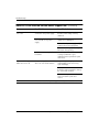
Deployment and Management
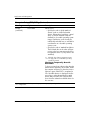
Computer Setup (F10) Utility (Continued)
Heading
Option
Description
Storage
(continued)
Device Configuration
(continued)
Drive Emulation
Allows you to select a drive emulation type for
a certain storage device. (For example, a Zip
drive can be made bootable by selecting
diskette emulation.)
Drive Type
Emulation Options
ATAPI Zip drive
None (treated as Other).
Diskette (treated as
diskette drive).
ATA Hard Disk
None (treated as Other)
Disk (treated as hard
drive)
Legacy Diskette
No emulation options
available.
CD-ROM
No emulation options
available.
ATAPI LS-120
None (treated as Other).
Diskette (treated as
diskette drive).
Multisector Transfers (ATA disks only)
Specifies how many sectors are transferred
per multi-sector PIO operation. Options
(subject to device capabilities) are Disabled,
8, and 16.
Transfer Mode (IDE devices only)
Specifies the active data transfer mode.
Options (subject to device capabilities)
are PIO 0, Max PIO, Enhanced DMA, Ultra
DMA 0, and Max UDMA.
for specific Computer Setup options may vary depending on the hardware
✎ Support
configuration.
Setup and Installation Guide
www.hp.com
5-7
Deployment and Management
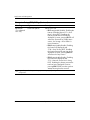
Computer Setup (F10) Utility (Continued)
Heading
Option
Description
Storage
(continued)
Device Configuration
(continued)
Translation Mode (ATA disks only)
Lets you select the translation mode to be
used for the device. This enables the BIOS to
access disks partitioned and formatted on
other systems and may be necessary for
users of older versions of UNIX (e.g., SCO
UNIX version 3.2). Options are Automatic,
Bit-Shift, LBA Assisted, User, and None.
Ordinarily, the translation
Ä CAUTION:
mode selected automatically by the BIOS
should not be changed. If the selected
translation mode is not compatible with
the translation mode that was active when
the disk was partitioned and formatted,
the data on the disk will be inaccessible.
Default Values IDE
Allows you to specify the default values for the
Multisector Transfers, Transfer Mode, and
Translation Mode for ATA devices.
Translation Parameters (ATA disks only)
feature appears only when User
✎ This
translation mode is selected.
Allows you to specify the parameters (logical
cylinders, heads, and sectors per track) used
by the BIOS to translate disk I/O requests
(from the operating system or an application)
into terms the hard drive can accept. Logical
cylinders may not exceed 1024. The number
of heads may not exceed 256. The number of
sectors per track may not exceed 63. These
fields are only visible and changeable when
the drive translation mode is set to User.
for specific Computer Setup options may vary depending on the hardware
✎ Support
configuration.
5-8
www.hp.com
Setup and Installation Guide
Deployment and Management
Computer Setup (F10) Utility (Continued)
Heading
Option
Description
Storage
(continued)
Storage Options
Removable Media Boot
Enables/disables ability to boot the system
from removable media.
Removable Media Write
Enables/disables ability to write data to
removable media.
saving changes to Removable
✎ After
Media Write, the computer will restart.
Turn the computer off, then on, manually.
BIOS IDE DMA Transfers
(enable/disable) Allows you to control how
BIOS disk I/O requests are serviced. When
“Enable” is selected, the BIOS will service
ATA disk read and write requests with DMA
data transfers. When “Disable” is selected,
the BIOS will service ATA disk read and write
requests with PIO data transfers.
DPS Self-Test
Allows you to execute self-tests on ATA hard
drives capable of performing the Drive
Protection System (DPS) self-tests.
selection will only appear when at
✎ This
least one drive capable of performing the
DPS self-tests is attached to the system.
for specific Computer Setup options may vary depending on the hardware
✎ Support
configuration.
Setup and Installation Guide
www.hp.com
5-9
Deployment and Management
Computer Setup (F10) Utility (Continued)
Heading
Option
Description
Storage
(continued)
Boot Order
Allows you to:
• Specify the order in which attached
devices (such as a USB flash media
device, diskette drive, hard drive, optical
drive, or network interface card) are
checked for a bootable operating system
image. Each device on the list may be
individually excluded from or included for
consideration as a bootable operating
system source.
• Specify the order of attached hard drives.
The first hard drive in the order will have
priority in the boot sequence and will be
recognized as drive C (if any devices are
attached).
drive lettering assignments may
✎ MS-DOS
not apply after a non-MS-DOS operating
system has started.
Shortcut to Temporarily Override
Boot Order
To boot one time from a device other than the
default device specified in Boot Order, restart
the computer and press F9 when the monitor
light turns green. After POST is completed, a
list of bootable devices is displayed. Use the
arrow keys to select the preferred bootable
device and press Enter. The computer then
boots from the selected non-default device for
this one time.
for specific Computer Setup options may vary depending on the hardware
✎ Support
configuration.
5-10
www.hp.com
Setup and Installation Guide
Deployment and Management
Computer Setup (F10) Utility (Continued)
Heading
Option
Description
Security
Setup Password
Allows you to set and enable setup
(administrator) password.
setup password is set, it is required
✎ Iftothechange
Computer Setup options, flash
the ROM, and make changes to certain
plug and play settings under Windows.
Device Security
Device Available/Device Hidden
• All USB ports
Network Service Boot
Enables/disables the computer’s ability to
boot from an operating system installed on
a network server.
System IDs
Allows you to enter:
• Asset Tag (18-byte identifier) and
ownership Tag (80-byte identifier
displayed during POST).
• Ownership Tag
• Operating System
• System Name
• UUID
• Keyboard locale setting (for example,
U.S. or Deutsche) for System ID entry.
for specific Computer Setup options may vary depending on the hardware
✎ Support
configuration.
Setup and Installation Guide
www.hp.com
5-11
Deployment and Management
Computer Setup (F10) Utility (Continued)
Heading
Option
Description
Advanced*
*For advanced
users only.
Power-On Options
Allows you to set:
• F9 Prompt (enable/disable). Enabling this
feature will display the text “F9 = Boot
Menu” during POST. Disabling this
feature prevents the text from being
displayed. However, pressing F9 will still
access the Shortcut Boot [Order] Menu
screen. See Storage > Boot Order for
more information.
• F10 Prompt (enable/disable). Enabling
this feature will display the text
“F10 = Setup” during POST. Disabling
this feature prevents the text from being
displayed. However, pressing F10 will
still access the Setup screen.
• F12 Prompt (enable/disable). Enabling
this feature will display the text
“F12 = Network Service Boot” during
POST. Disabling this feature prevents the
text from being displayed. However,
pressing F12 will still force the system to
attempt booting from the network.
for specific Computer Setup options may vary depending on the hardware
✎ Support
configuration.
5-12
www.hp.com
Setup and Installation Guide
Deployment and Management
Computer Setup (F10) Utility (Continued)
Heading
Option
Description
Advanced*
(continued)
*For advanced
users only.
Power-On Options
(continued)
Allows you to set: (continued)
• Option ROM Prompt (enable/disable)
Enabling this feature will cause the system
to display a message before loading
option ROMs. (This feature is supported
on some models only.)
• POST Delay (in seconds) (None, 5, 10
15, or 20). Enabling this feature will add
a user-specified delay to the POST
process. This delay is sometimes needed
for hard disks on some PCI cards that spin
up very slowly; so slowly that they are not
ready to boot by the time POST is
finished. The POST delay also gives you
more time to select F10 to enter
Computer (F10) Setup.
• I/O APIC Mode (enable/disable).
Enabling this feature will allow Microsoft
Windows Operating Systems to run
optimally. This feature must be disabled
for certain non-Microsoft Operating
Systems to work properly.
• ACPI/USB Buffers @ Top of Memory
(enable/disable). Enabling this feature
places USB memory buffers at the top
of memory. The advantage is that
some amount of memory below 1 MB is
freed up for use by option ROMs. The
disadvantage is that a popular memory
manager, HIMEM.SYS, does not work
properly when USB buffers are at top of
memory AND the system has 64 MB or
less of RAM.
for specific Computer Setup options may vary depending on the hardware
✎ Support
configuration.
Setup and Installation Guide
www.hp.com
5-13
Deployment and Management
Computer Setup (F10) Utility (Continued)
Heading
Option
Advanced*
(continued)
*For advanced
users only.
PCI Devices
Description
• Lists currently installed PCI devices and
their IRQ settings.
• Allows you to reconfigure IRQ settings for
these devices or to disable them entirely.
These settings have no effect under an
APIC-based operating system.
Device Options
Allows you to set:
• Num Lock State at Power-On (off/on).
• S5 Wake on LAN (enable/disable).
• To disable Wake on LAN during the off
state (S5), use the arrow (left and right)
keys to select the Advanced > Device
Options menu and set the S5 Wake on
Lan feature to “Off.” This obtains the
lowest power consumption available on
the computer during S5. It does not
affect the ability of the computer to
Wake on LAN from suspend or
hibernation, but will prevent it from
waking from S5 via the network. It does
not affect operation of the network
connection while the computer is on.
• If a network connection is not required,
completely disable the network
controller (NIC) by using the arrow (left
and right) keys to select the Security >
Device Security menu. Set the Network
Controller option to “Device Hidden.”
This prevents the network controller from
being used by the operating system and
reduces the power used by the computer
in S5.
• Processor Cache (enable/disable).
• Spread Spectrum (enable/disable)
for specific Computer Setup options may vary depending on the hardware
✎ Support
configuration.
5-14
www.hp.com
Setup and Installation Guide
Deployment and Management
Computer Setup (F10) Utility (Continued)
Heading
Option
Description
Advanced*
(continued)
*For advanced
users only.
Device Options
(continued)
Allows you to set: (continued)
• NIC PXE Option ROM Download
(enable/disable). The BIOS contains an
embedded NIC option ROM to allow the
unit to boot through the network to a PXE
server. This is typically used to download
a corporate image to a hard drive. The
NIC option ROM takes up memory space
below 1MB commonly referred to as DOS
Compatibility Hole (DCH) space. This
space is limited. This F10 option will
allow users to disable the downloading of
this embedded NIC option ROM thus
giving more DCH space for additional
PCI cards which may need option ROM
space. The default will be to have the NIC
option-ROM-enabled.
• USB 2.0 Capability (automatic,
enable/disable)
for specific Computer Setup options may vary depending on the hardware
✎ Support
configuration.
Restoring the Configuration Settings
Restoring the configuration settings requires that you first perform
the Save To Removable Media command within the Computer Setup
(F10) Utility before Restore is needed.
is recommended that you save any modified computer
✎ Itconfiguration
settings to removable media, and save the removable
media for possible future use.
To restore the configuration, insert the removable media with the
saved configuration into a USB drive (attached via the diagnostic
adapter) and perform the Restore from Removable Media command
with the Computer Setup (F10) Utility.
Setup and Installation Guide
www.hp.com
5-15
Deployment and Management
must install an optional graphics diagnostic card on the Blade PC
✎ You
before you can use a monitor with the diagnostic adapter.
Restoring the configuration setting can also be performed from the
operating system using System Software Manager (SSM). For more
information, refer to the following website: www.hp.com/go/ssm
Flashing the Blade PC ROM
There are two methods for flashing your ROM:
■
Upgrading the Blade PC ROM using Flashbin Utility
■
Remote ROM flash
Upgrading the Blade PC ROM Using Flashbin Utility
Use Blade PC Flashbin utilities to upgrade your system BIOS.
following steps also apply when recovering the system if the
✎ The
system enters Boot Block mode due to a ROM flash failure.
information on creating a bootable Drive Key, refer to the
✎ For
following website:
http://wwss1pro.compaq.com/support/reference_library/viewdocum
ent.asp?source=338111.xml&dt=21
To use the Flashbin Utility:
1. Download the latest version of the system BIOS and the Flashbin
utility for the Blade PC onto a USB Drive Key. The latest system
BIOS and Flashbin utility are available at: www.hp.com
2. Power down the blade. See the “Powering Down a Blade PC”
section in Chapter 4.
3. Remove the Blade PC. See the “Removing a Blade PC” section in
Chapter 4.
4. Install the optional graphics diagnostic card on the Blade PC.
5. Install the Blade PC in the enclosure.
6. Attach the diagnostic adapter to the Blade PC.
5-16
www.hp.com
Setup and Installation Guide
Deployment and Management
7. Attach the USB Drive Key with the downloaded system BIOS, a
keyboard, a monitor, and a mouse to the diagnostic adapter.
8. To begin flashing the ROM:
a. Power on the Blade.
b. Change to the directory containing the BIOS and Flashbin
utility.
c. Type Flashbin.
d. Press Enter.
Remote ROM Flash
Remote ROM Flash allows the system administrator to safely
upgrade the ROM from a remote location. Enabling the system
administrator to perform this task remotely results in a consistent
deployment of and greater control over HP ROM images over the
network. It also results in greater productivity and lower total cost of
ownership.
For more information on remote ROM flash, refer to the following
website: www.hp.com/go/ssm
HP PC Blade Enclosure Integrated Administrator
The HP PC Blade Enclosure Integrated Administrator is a centralized
management and monitoring system for the HP PC Blade Enclosure
and blade PCs. The Integrated Administrator acts as a combination
terminal server and remote power controller, enabling out-of-band,
secure, serial console connections to all Blade PCs in the enclosure,
and offers all of the following:
■
Setup and Installation Guide
Full Command Line Interface (CLI) and Web interface
❏
Blade PC privileges can be set on a user basis
❏
Virtual power button to power Blade PC on or off
❏
More than 100 scriptable commands to enable automated
deployment and management
www.hp.com
5-17
Deployment and Management
■
■
Remote administration
❏
Enables access to Blade PC’s serial console
❏
Enables full control over Blade PC’s Power-On Self Test
(POST) and boot process, including the Computer Setup
(F10) Utility
Hardware health monitoring
The Integrated Administrator monitors and controls the enclosure
fans, temperature sensors, power supplies, and blade status.
■
■
■
5-18
Offline console buffering (when not connected) and event
logging
❏
Operating system console logging
❏
Blade PC and enclosure hardware events
Security features
❏
Secure Shell access
❏
User administration for up to 25 users
❏
Event generation for invalid login attempts
❏
Logging of user actions in event log
❏
Selective enabling of all protocols, such as Telnet
❏
Out-of-band management using Integrated Administrator's
RS-232 console
❏
Secure Sockets Layer (SSL) (Web interface)
❏
Customer installable SSL certificates
Increased availability
❏
The Integrated Administrator is a self-contained embedded
system with its own processor, memory, NIC, and flash
ROM.
❏
The enclosure itself is intelligent and fault-tolerant, and
continues to function even if the Integrated Administrator
fails.
❏
The Integrated Administrator enables online firmware update
with code signing to ensure only certified software releases
are installed.
www.hp.com
Setup and Installation Guide
Deployment and Management
■
HP Systems Insight Manager integration
❏
HP Systems Insight Manager identifies the Integrated
Administrator as a blade Management Processor.
❏
The Integrated Administrator status is part of the Blade PC
status. If the Integrated Administrator is degraded, all Blade
PCs managed by that Integrated Administrator are shown as
degraded.
❏
HP Systems Insight Manager can capture the Integrated
Administrator SNMP traps.
❏
HP Systems Insight Manager enables the user to launch the
Integrated Administrator Web interface.
The Integrated Administrator Web interface enables full access and
control of the Blade PCs and enclosure via a browser, including:
■
Enclosure management
❏
Monitor fans, power supplies, and temperature
❏
Graceful enclosure and Blade PC power shutdown
❏
Enclosure unit identification (UID) control
❏
Interface to management tools and utilities associated with
the optional interconnect switch
For details on the management tools and utilities associated
with the optional interconnect switch, refer to the HP PC
Blade Enclosure C-GbE Interconnect Switch User Guide.
■
■
Setup and Installation Guide
Blade PC management
❏
Virtual power and unit identification (UID) buttons
❏
Remote serial console
❏
General health status
User management
❏
Add/remove/modify administrators/groups/users
❏
Blade PCs assigned to groups
❏
Two levels of user access to groups
www.hp.com
5-19
Deployment and Management
For more information, including instructions on flashing the
Integrated Administrator ROM, refer to the HP PC Blade Enclosure
Integrated Administrator User Guide on the Documentation CD that
ships with your enclosure.
Blade PC Event Messages
The event list displays the affected components and the associated
error messages.
The following table identifies the event types (affected components)
and associated event messages.
Blade PC Event Messages
Event Type
Event Message
Blade PC Environment
Overheat condition*
System Overheating (Zone X)
Operating System
Automatic operating system
shutdown
Automatic Operating System Shutdown Initiated Due to Fan
Failure
Automatic Operating System Shutdown Initiated Due to
Overheat Condition
Enclosure Environment
Overheat Condition
The Integrated Administrator has issued an alert that its health
state has changed **
Fan Failure
The Integrated Administrator has issued an alert that its health
state has changed **
✎ *For specific operating temperature ranges, see Appendix F, “Specifications.”
**Refer to the Integrated Administrator log for detailed messages.
5-20
www.hp.com
Setup and Installation Guide
Deployment and Management
HP Systems Insight Manager
IMPORTANT: You can install HP Systems Insight Manager using the
Management CD included with your enclosure or download it from the
HP website.
HP Systems Insight Manager provides in-depth fault, inventory, and
configuration management of HP server platforms (including
hundreds of Blade PCs) from a single console. You can use HP
Systems Insight Manager to view each Blade PC and the Integrated
Administrator of each blade enclosure. The system parameters that
are monitored describe the status of all key Blade PC and enclosure
components. By being able to view the events that occur to these
components, you can take immediate action.
Use the instructions in the following section to view and print the
event list from within HP Systems Insight Manager. You can also
mark a critical or caution event as repaired after the affected
component has been replaced.
Viewing the Event List
To view the event list for discovered systems:
1. In the HP Systems Insight Manager System Lists window,
a. Expand the System List.
b. Expand the Systems by Type.
c. Select All Systems, All Enclosures, or All Clients to view
the list of Blade PCs or enclosures.
2. On the displayed list, click on the appropriate enclosure or client.
3. Click on the Events tab on the newly displayed page.
4. Click on an event for the event details.
Setup and Installation Guide
www.hp.com
5-21
Deployment and Management
Printing the Event List
To print the List of Events, click on the Print button on the lower
right corner of the event page.
To print the details of an individual event:
1. Click on the event.
2. Scroll down the page and click on View Printable Details.
3. When the new page opens, click on the browser File/Print.
HP PC Blade Enclosure C-GbE Interconnect Switch
Management Tools and Utilities
The interconnect switch offers a wide variety of out-of-band and
in-band configuration and management capabilities. The interconnect
switch includes a default configuration for immediate operation.
Configuration and management is supported on any of the
interconnect switch’s four uplink ports as well as on the Integrated
Administrator management Ethernet and serial console connectors.
Supported interfaces include:
■
■
■
HTTP-based via Web browser
❏
Full-featured management interface
❏
Supported on all common Web browsers
❏
Includes graphical representations of the interconnect switch
❏
Access via any Gigabit Ethernet uplink connector and the
Integrated Administrator management connector
Menu driven console with local and Telnet access
❏
Full-featured management interface
❏
Access locally via the Integrated Administrator console
connector or remotely via Telnet
SNMP agent support for interconnect switch management,
configuration, and monitoring using generic SNMP manager with
an MIB compiler
❏
5-22
SNMP V1-V3 (RFC 1157) and RMON V1 (RFC 1757;
groups 1 Statistics, 2 History, 3 Alarm, and 9 event) support
www.hp.com
Setup and Installation Guide
Deployment and Management
❏
Scripting capabilities are available via an SNMP scripting
utility
❏
Access via any interconnect switch uplink connector and the
Integrated Administrator management connector
The interconnect switch also offers additional configuration and
management features including:
■
■
Interconnect switch configuration and restore via TFTP server
❏
Upload to and download from a TFTP server a copy of the
interconnect switch configuration
❏
Enables rapid deployment of multiple interconnect switches
with similar configuration
❏
Provides backup and restore capabilities
Connector mirroring support for networking diagnostics
Monitor network traffic on an interconnect switch connector by
mirroring a copy of its data to a different (mirror) connector
■
Link speed and activity LEDs on each Gigabit Ethernet uplink
connector
■
Two-level (level 1, level 15) username and password for all
management interfaces
Setup and Installation Guide
❏
Ability to recover from lost management-level password
❏
Configurable time-out period on Telnet and console sessions
www.hp.com
5-23
A
Regulatory Compliance Notices
Regulatory Compliance Identification Numbers
For the purpose of regulatory compliance certifications and
identification, your product has been assigned a unique series
number. The series number can be found on the product nameplate
label, along with all required approval markings and information.
When requesting compliance information for this product, always
refer to this series number. The series number should not be confused
with the marketing name or model number of the product.
Federal Communications Commission Notice
Part 15 of the Federal Communications Commission (FCC) Rules
and Regulations has established Radio Frequency (RF) emission
limits to provide an interference-free radio frequency spectrum. Many
electronic devices, including computers, generate RF energy
incidental to their intended function and are, therefore, covered by
these rules. These rules place computers and related peripheral
devices into two classes, A and B, depending upon their intended
installation. Class A devices are those that may reasonably be
expected to be installed in a business or commercial environment.
Class B devices are those that may reasonably be expected to be
installed in a residential environment (for example, personal
computers). The FCC requires devices in both classes to bear a label
indicating the interference potential of the device as well as additional
operating instructions for the user.
The rating label on the device shows the classification (A or B) of the
equipment. Class B devices have an FCC logo or FCC ID on the
label. Class A devices do not have an FCC logo or FCC ID on the
label. After the Class of the device is determined, refer to the
corresponding statement in the following sections.
Setup and Installation Guide
www.hp.com
A-1
Regulatory Compliance Notices
Class A Equipment
This equipment has been tested and found to comply with the limits
for a Class A digital device, pursuant to Part 15 of the FCC Rules.
These limits are designed to provide reasonable protection against
harmful interference when the equipment is operated in a commercial
environment. This equipment generates, uses, and can radiate radio
frequency energy and, if not installed and used in accordance with the
instructions, may cause harmful interference to radio
communications. Operation of this equipment in a residential area is
likely to cause harmful interference, in which case the user will be
required to correct the interference at personal expense.
Class B Equipment
This equipment has been tested and found to comply with the limits
for a Class B digital device, pursuant to Part 15 of the FCC Rules.
These limits are designed to provide reasonable protection against
harmful interference in a residential installation. This equipment
generates, uses, and can radiate radio frequency energy and, if not
installed and used in accordance with the instructions, may cause
harmful interference to radio communications. However, there is no
guarantee that interference will not occur in a particular installation.
If this equipment does cause harmful interference to radio or
television reception, which can be determined by turning the
equipment off and on, the user is encouraged to try to correct the
interference by one or more of the following measures:
A-2
■
Reorient or relocate the receiving antenna
■
Increase the separation between the equipment and receiver
■
Connect the equipment into an outlet on a circuit that is different
from that to which the receiver is connected
■
Consult the dealer or an experienced radio or television
technician for help
www.hp.com
Setup and Installation Guide
Regulatory Compliance Notices
Declaration of Conformity for Products Marked with the
FCC Logo, United States Only
This device complies with Part 15 of the FCC Rules. Operation is
subject to the following two conditions: (1) this device may not cause
harmful interference, and (2) this device must accept any interference
received, including interference that may cause undesired operation.
For questions regarding your product, contact us by mail or
telephone:
■
Hewlett-Packard Company
P. O. Box 692000, Mail Stop 530113
Houston, Texas 77269-2000
■
1-800-HP-INVENT (1-800-474-6836) (For continuous quality
improvement, calls may be recorded or monitored.)
For questions regarding this FCC declaration, contact us by mail or
telephone:
■
Hewlett-Packard Company
P. O. Box 692000, Mail Stop 510101
Houston, Texas 77269-2000
■
281-514-3333
To identify this product, refer to the part, series, or model number
found on the product.
Modifications
The FCC requires the user to be notified that any changes or
modifications made to this device that are not expressly approved by
Hewlett-Packard Company may void the user’s authority to operate
the equipment.
Cables
Connections to this device must be made with shielded cables with
metallic RFI/EMI connector hoods in order to maintain compliance
with FCC Rules and Regulations.
Setup and Installation Guide
www.hp.com
A-3
Regulatory Compliance Notices
Canadian Notice (Avis Canadien)
Class A Equipment
This Class A digital apparatus meets all requirements of the Canadian
Interference-Causing Equipment Regulations.
Cet appareil numérique de la classe A respecte toutes les exigences
du Règlement sur le matériel brouilleur du Canada.
Class B Equipment
This Class B digital apparatus meets all requirements of the Canadian
Interference-Causing Equipment Regulations.
Cet appareil numérique de la classe B respecte toutes les exigences du
Règlement sur le matériel brouilleur du Canada.
European Union Notice
This product complies with the following EU directives:
■
Low Voltage Directive 73/23/EEC
■
EMC Directive 89/336/EEC
Compliance with the directives implies conformity to applicable
harmonized European standards (Europen Norms) which are listed on
the EU Declaration of Conformity issued by Hewlett-Packard for this
product or product family. This compliance is indicated by the
following conformity markings placed on the product:
This marking is valid for non-Telecom products
and EU harmonized Telecom products (e.g. Bluetooth).
xxxx*
This marking is valid for EU non-harmonized Telecom products .
*Notified body number (used only if applicable - refer to the product label)
A-4
www.hp.com
Setup and Installation Guide
Regulatory Compliance Notices
Japanese Notice
Korean Notice
Class A Equipment
Class B Equipment
Setup and Installation Guide
www.hp.com
A-5
Regulatory Compliance Notices
Taiwanese Notice
Laser Compliance
This product may be provided with an optical storage device (that is,
CD or DVD drive) and/or fiber optic tranceiver. Each of these devices
contains a laser that is classified as a Class 1 Laser Product in
accordance with US FDA regulations and the IEC 60825-1. The
product does not emit hazardous laser radiation.
Each laser product complies with 21 CFR 1040.10 and 1040.11
except for deviations pursuant to Laser Notice No. 50, dated May 27,
2001 and with IEC 60825-1:1993/A2:2001.
Å
WARNING: Use of controls or adjustments or performance of
procedures other than those specified herein or in the laser product’s
installation guide may result in hazardous radiation exposure. To reduce
the risk of exposure to hazardous radiation:
• Do not try to open the module enclosure. There are no
user-serviceable components inside.
• Do not operate controls, make adjustments, or perform procedures
to the laser device other than those specified herein.
• Allow only HP Authorized Service technicians to repair the unit.
A-6
www.hp.com
Setup and Installation Guide
Regulatory Compliance Notices
Battery Replacement Notice
Your computer is equipped with a lithium manganese dioxide, a
vanadium pentoxide, or an alkaline internal battery or battery pack.
There is a danger of explosion and risk of personal injury if the
battery is incorrectly replaced or mistreated. Replacement is to be
done by an authorized service provider using the spare designated for
this product. For more information about battery replacement or
proper disposal, contact your authorized reseller or your authorized
service provider.
Å
WARNING: Your computer contains an internal lithium manganese
dioxide, a vanadium pentoxide, or an alkaline battery pack. There is risk
of fire and burns if the battery pack is not properly handled. To reduce the
risk of personal injury:
• Do not attempt to recharge the battery.
• Do not expose to temperatures higher than 60°C.
• Do not disassemble, crush, puncture, short external contacts, or
dispose of in fire or water.
• Replace only with the spare designated for this product.
Batteries, battery packs, and accumulators should not
be disposed of together with the general household
waste. To forward them to recycling or proper
disposal, please use the public collection system or
return them to HP, your authorized HP partners, or
their agents.
Setup and Installation Guide
www.hp.com
A-7
B
Electrostatic Discharge
To prevent damaging the system, be aware of the precautions you
need to follow when setting up the system or handling parts. A
discharge of static electricity from a finger or other conductor may
damage system boards or other static-sensitive devices. This type of
damage may reduce the life expectancy of the device.
Preventing Electrostatic Damage
To prevent electrostatic damage, observe the following precautions:
■
Avoid hand contact by transporting and storing products in
static-safe containers.
■
Keep electrostatic-sensitive parts in their containers until they
arrive at static-free workstations.
■
Place parts on a grounded surface before removing them from
their containers.
■
Avoid touching pins, leads, or circuitry.
■
Always be properly grounded when touching a static-sensitive
component or assembly.
Setup and Installation Guide
www.hp.com
B-1
Electrostatic Discharge
Grounding Methods
There are several methods for grounding. Use one or more of the
following methods when handling or installing electrostatic-sensitive
parts:
B-2
■
Use a wrist strap connected by a ground cord to a grounded
workstation or computer chassis. Wrist straps are flexible straps
with a minimum of 1 megohm ± 10 percent resistance in the
ground cords. To provide proper ground, wear the strap snug
against the skin.
■
Use heel straps, toe straps, or boot straps at standing
workstations. Wear the straps on both feet when standing on
conductive floors or dissipating floor mats.
■
Use conductive field service tools.
■
Use a portable field service kit with a folding static-dissipating
work mat.
www.hp.com
Setup and Installation Guide
C
POST Error Messages
Use POST error messages to assist in troubleshooting and performing
basic diagnostic functions. The following table lists the numeric
codes and text messages specific to Blade PCs.
the recommended actions in the order in which they are
✎ Attempt
listed.
POST Error Messages
Code/Message
Health LED
Possible Cause
101-Option ROM
Checksum Error
Red
Blade system board has
failed.
Recommended Action
1. Clear CMOS.
2. Flash the system ROM.
3. Replace the blade.
102/103-System
Board Failure
Red
162-System Options
Not Set
Amber
Blade system board has
failed.
1. Clear CMOS
CMOS was cleared or
the blade’s battery has
failed.
1. Reset the system time
and date in Computer
Setup (F10).
2. Replace the blade.
2. Replace the blade’s RTC
battery.
163-Time & Date Not
Set
Amber
Setup and Installation Guide
CMOS was cleared
www.hp.com
Reset the system time and
date in Computer Setup
(F10).
C-1
POST Error Messages
POST Error Messages (Continued)
Code/Message
Health LED
Possible Cause
164-Memory Size
Error
Amber
Memory configuration is
incorrect.
Recommended Action
1. Ensure the SODIMM(s)
are properly installed.
2. Verify that the proper
type of SODIMM is
installed.
3. Reseat the SODIMM(s).
4. Replace the SODIMM(s).
5. Replace the blade.
201-Memory Error
Red
An SODIMM may not be
seated correctly or is
bad.
1. Ensure the SODIMM(s)
are properly installed.
2. Verify that the proper
type of SODIMM is
installed.
3. Reseat the SODIMM(s).
4. Replace the SODIMM(s).
5. Replace the blade.
303-Keyboard
Controller Error
Amber
Keyboard controller has
failed.
1. Reconnect the keyboard
with the blade turned off.
2. Use a different keyboard
that is known to work
properly.
3. Replace the blade.
304-Keyboard or
System Unit Error
Amber
Keyboard has failed.
1. Reconnect the keyboard
with the blade turned off.
2. Use a different keyboard
that is known to work
properly.
3. Replace the blade.
1720-SMART Hard
Drive detects imminent
failure
Amber
Hard drive is about to
fail.
1. Run Drive Protection
System if applicable.
2. Apply firmware patch
(www.hp.com/support).
3. Back up contents and
replace the hard drive.
C-2
www.hp.com
Setup and Installation Guide
POST Error Messages
POST Error Messages (Continued)
Code/Message
Health LED
Possible Cause
1780-Disk 0 Failure
Amber
Hard drive has failed.
Recommended Action
1. Run IDE Self-Test from
Computer Setup (F10).
2. Replace the hard drive.
1782-Disk Controller
Error
Red
Hard drive circuitry error
has occurred.
1. Run IDE Self-Test from
Computer Setup (F10).
2. Replace the hard drive.
3. Replace the blade.
1790-Disk 0 Error
Amber
Hard drive has failed.
1. Run IDE Self-Test from
Computer Setup (F10).
2. Replace the hard drive.
3. Replace the blade.
1800-Temperature
Alert
Amber
Internal temperature
exceeds specification.
1. Ensure that the system
fans are functioning
properly and that the
enclosure has adequate
ventilation.
2. Check the processor heat
sink.
3. Replace the blade.
1998-Master Boot
Record Backup has
been lost. Press any
key to enter Setup to
update the MBR
Backup.
Amber
The previously saved
copy of the MBR has
been corrupted.
Invalid Electronic
Serial Number
Amber
Electronic serial number
has been lost.
Run Computer Setup to
update the MBR backup.
1. Run Computer Setup. If
data is loaded/will not
allow changes,
download SP5572.EXE
(SNZERO.EXE) from
www.hp.com.
2. Run Computer Setup,
enter serial number
under Security, System
ID, then save changes.
Setup and Installation Guide
www.hp.com
C-3
D
Troubleshooting
This appendix provides specific troubleshooting information for the
HP CCI solution. Use it to find details about the enclosure and Blade
PC startup and operation errors.
For information on LEDs and switches specific to the Blade PCs and
enclosure, see Appendix E, “LEDs and Switches.”
Å
WARNING: A risk of injury or damage to the equipment from
hazardous energy is present. The access door provides access to
hazardous energy circuits. The door should remain locked during normal
operation or troubleshooting, or the system should be installed in a
controlled access location where only qualified personnel have access to
the system.
This appendix includes the following topics:
■
When the enclosure does not start
You are provided with initial instructions on what to try and
where to go for help for the most common problems encountered
during initial enclosure startup.
■
Enclosure diagnostic steps
If the enclosure does not start after you have performed initial
troubleshooting procedures, use the tables in this section to
identify possible reasons for the problem and possible solutions.
■
When the Blade PC does not start
You are provided with initial instructions on what to try and
where to go for help for the most common problems encountered
during initial POST. The Blade PC automatically performs this
test each time you power up, before the Blade PC can load the
operating system and start running software applications.
Setup and Installation Guide
www.hp.com
D-1
Troubleshooting
■
Blade PC diagnostic steps
If the Blade PC does not start after you have performed initial
troubleshooting procedures, use the tables in this section to
identify possible reasons for the problem and possible solutions.
■
Problems after initial boot
Once the Blade PC has passed the POST, you may still encounter
errors, such as an inability to load your operating system. You are
provided with instructions on what to try and where to go for help
when you encounter errors after the Blade PC completes the
POST.
■
Remote troubleshooting
Some troubleshooting can be performed remotely. You are
provided with instructions for opening a remote console session,
accessing the Blade PC Computer Setup (F10) Utility, reviewing
Blade PC activity, and powering off a Blade PC.
D-2
www.hp.com
Setup and Installation Guide
Troubleshooting
When the Enclosure Does Not Start
This section provides systematic instructions on what to try and
where to go for help for the most common problems encountered
during initial startup of the HP PC Blade Enclosure. If you are having
specific Blade PC trouble, see the “When the Blade PC Does Not
Start” section in this appendix.
If the enclosure does not start:
1. Check the enclosure for the normal power up sequence:
a. The front panel enclosure health LED and rear panel fan
health, Integrated Administrator health, and power supply
LEDs turn to solid green.
b. The power supply fans and main fans start up.
2. Be sure that the enclosure is plugged into a working power outlet.
3. Be sure your power sources are working properly by checking the
power LED on each power supply in the rear of the enclosure.
For information about the location and function of all enclosure
LEDs, see Appendix E, “LEDs and Switches.”
4. Be sure your power supplies are working properly by checking
the fault LED on your power supplies in the back of the enclosure
(see Tables E-2 or E-3).
5. Be sure that the enclosure has power by checking the enclosure
power LED on the rear of the enclosure (see table E-2 or E-3).
6. Be sure the fans are functioning by checking the fan health LED
on the rear panel of the enclosure (see Table E-4).
7. Be sure the center wall assembly is delivering power to your
enclosure by checking if the enclosure health LED on the front of
the enclosure is illuminated (see Table E-1).
8. If the Integrated Administrator is rebooting repeatedly, be sure
that it is not rebooting due to a problem that initiates an Enclosure
Self Recovery (ESR) reboot.
Refer to the following sections in the HP PC Blade Enclosure
Integrated Administrator User Guide on the Documentation CD
that ships with your enclosure:
❏
Setup and Installation Guide
“Enclosure Self Recovery”
www.hp.com
D-3
Troubleshooting
❏
“System Short Circuit” for other continuous rebooting
problems
9. Restart the enclosure by pressing the enclosure power button on
the fan cage on the rear of the enclosure.
Ä
CAUTION: Pressing the enclosure power button while the enclosure is
running shuts down the enclosure and all Blade PCs.
IMPORTANT: If the enclosure does not restart, proceed to “Table D-1:
Enclosure Diagnostic Steps” in this appendix.
10. Be sure that connectors and components are seated properly.
Refer to the “General Loose Connections” section in the Servers
Troubleshooting Guide on the Documentation CD that ships with
your enclosure.
D-4
www.hp.com
Setup and Installation Guide
Troubleshooting
Enclosure Diagnostic Steps
If your enclosure does not function properly, use Table D-1 to
determine appropriate actions based on the symptoms observed. Start
with question 1 and work your way through the table in order to
narrow down possible causes and identify actions or solutions.
According to the answers you give to the questions in Table D-1, you
are directed to the appropriate table in the section that immediately
follows. That table outlines possible reasons for the problem, options
available to assist in diagnosis, and possible solutions.
Table D-1: Enclosure Diagnostic Steps
Question
Answer
Question 1: Is the power LED on both power
supplies solid green?
If yes, continue to Question 2 of this table.
If no, see Table D-2.
Question 2: Is the fault LED on both power
supplies off?
If yes, continue to Question 3 of this table.
If no, see Table D-3.
Question 3: Is the enclosure power LED on the
rear panel green?
If yes, continue to Question 4 of this table.
If no, see Table D-4.
Question 4: Is the enclosure health LED on the
front of the enclosure on?
If yes, continue to Question 5 of this table.
If no, see Table D-5.
Question 5: Is the local management console
displaying information when connected to the
enclosure?
If yes, use the displayed information for further
diagnosis.
If no, see table D-6, or continue to Question 6.
Question 6: Is the Integrated Administrator health
LED green?
If yes, continue to Question 7 of this table.
If no, see Table D-7.
Question 7: Is the fan health LED green?
If yes, and you are still unable to access the local
console, contact HP or your authorized service
provider for parts and service.
If no, see Table D-8.
Ä
CAUTION: Pressing the enclosure power button while the enclosure is
running shuts down the enclosure and all Blade PCs.
Setup and Installation Guide
www.hp.com
D-5
Troubleshooting
Table D-2: Is the Power LED on Both Power Supplies Solid Green?
Answer
Possible Reasons
Possible Solutions
No, they are both off.
The power supply is not
connected to AC power or no
AC power is available.
Be sure that all power cords are
connected to the power supplies.
One power supply is not
connected to AC power or no
AC power is available.
Be sure that the power cord is
connected to the power supply. You
still have adequate power, but no
redundancy; return to Table D-1.
No, one is green and one
is off.
Be sure that all power cords are
plugged into working, grounded
outlets.
Be sure that the power cord is
plugged into a working, grounded
outlet. You still have adequate
power, but no redundancy; return to
Table D-1.
No, they are both
blinking green.
Both power supplies are in
standby mode.
Press the enclosure power button on
the redundant fan cage in the rear of
the enclosure.
Caution: Pressing the enclosure
power button while the enclosure is
running shuts down the enclosure and
all Blade PCs.
Be sure that the pins on the power
supplies are not damaged.
Be sure that the power supplies are
fully seated in the power supply bays.
No, one is solid green
and one is blinking
green.
One power supply is in standby
mode.
Be sure that the pins on the power
supplies are not damaged. You still
have adequate power, but no
redundancy; return to Table D-1.
Be sure that the power supplies are
fully seated in the power supply bays.
You still have adequate power, but
no redundancy; return to Table D-1.
Yes.
D-6
If both power LEDs are solid green, return to Table D-1.
www.hp.com
Setup and Installation Guide
Troubleshooting
Table D-3: Is the Fault LED on Both Power Supplies Off?
Answer
Possible Reasons
Possible Solutions
No, one or both are
amber.
The power supply is not
connected to AC power or no
AC power is available.
Be sure that all power cords are
connected to the power supplies.
An over-voltage condition has
occurred.
Check your power source to be sure
that the correct voltage is being
delivered.
Be sure that all power cords are
plugged into working, grounded
outlets.
Be sure that the pins on the power
supplies are not damaged.
Be sure that the power supplies are
fully seated in the power supply bays.
No, one or both are
blinking amber.
An over-temperature condition
has occurred.
Be sure that nothing is preventing the
power supply fan blades from
spinning.
At least one power supply fan
has failed.
Contact HP or your authorized
service provider for parts and
service.
The power supply has shut off
due to an over-current condition.
Inspect the power supply and center
wall assembly connectors for any
signs of damage.
Look at all other health LEDs to
determine which component may be
causing the over-current condition.
Contact HP or your authorized
service provider for parts and
service.
Setup and Installation Guide
www.hp.com
D-7
Troubleshooting
Table D-3: Is the Fault LED on Both Power Supplies Off? (Continued)
Answer
Possible Reasons
Possible Solutions
No, one is amber and
one is off.
An over-voltage condition has
occurred on one power supply.
Check your power source to be sure
that the correct voltage is being
delivered.
An over-temperature condition
has occurred on one power
supply.
Be sure that the pins on the power
supply are not damaged.
Be sure that the power supply is fully
seated in the power supply bays.
Be sure that nothing is preventing the
fan blades from spinning.
No, one is blinking
amber and one is off.
At least one power supply fan
has failed.
You no longer have adequate
cooling. Contact HP or your
authorized service provider for parts
and service.
One power supply has shut off
due to an over-current situation.
Inspect the power supply and center
wall assembly connectors for any
signs of damage.
Check other health LEDs to determine
if another component may be causing
the over-current condition.
Contact HP or your authorized
service provider for parts and
service.
Yes.
D-8
If the fault LEDs on both power supplies are off, return to Table D-1.
www.hp.com
Setup and Installation Guide
Troubleshooting
Ä
CAUTION: Pressing the enclosure power button while the enclosure is
running shuts down the enclosure and all Blade PCs.
Table D-4: Is the Enclosure Power LED on the Rear Panel Green?
Answer
Possible Reasons
Possible Solutions
No, it is off.
The cable is not properly
connected between the fan
backplane and the power
backplane.
Be sure that the connectors on the fan
cable are properly seated and not
damaged.
The interconnect tray is not fully
inserted.
Remove and reseat the interconnect
tray.
The Integrated Administrator
module is not properly seated.
Contact HP or your authorized
service provider for parts and
service.
The fan backplane assembly has
failed.
The connector on the power
backplane is damaged.
The power backplane has failed.
No, it is amber.
The enclosure is in standby
mode.
Yes, it is green.
If the enclosure power LED is green, return to Table D-1.
Setup and Installation Guide
www.hp.com
Push the enclosure power button on
the fan cage at the rear of the
enclosure.
Caution: Pressing the enclosure
power button while the enclosure is
running shuts down the enclosure and
all Blade PCs.
D-9
Troubleshooting
Table D-5: Is the Enclosure Health LED on the Front of the Enclosure On?
Answer
Possible Reasons
Possible Solutions
No, it is off.
The enclosure status cable is
disconnected from the center
wall assembly or the enclosure
status assembly.
Securely attach the enclosure status
cable.
The enclosure status assembly or
the center wall assembly is not
functioning properly.
Contact HP or your authorized
service provider for parts and
service.
A system component is
degraded but your system is still
functional.
Check your local or remote console
for error messages. Go to Table D-6.
Yes, it is amber.
Check system fans. Go to Table D-8.
Contact HP or your authorized
service provider for parts and
service.
Yes, it is red.
A system component has a
critical failure.
Check your local or remote console
for error messages. Go to Table D-6.
Check system fans. Go to Table D-8.
Contact HP or your authorized
service provider for parts and
service.
Yes, it is green.
D-10
The Integrated Administrator has
not detected any degraded or
failed components.
www.hp.com
Check your local or remote console
for error messages. Go toTable D-6.
Contact HP or your authorized
service provider for parts and
service.
Setup and Installation Guide
Troubleshooting
Table D-6: Is the Local Management Console Displaying Information
When Connected to the Enclosure?
Answer
Possible Reasons
Possible Solutions
No.
The local management console
may not be connected properly.
Be sure that the local management
console cable is securely connected.
The Integrated Administrator
module has failed.
Go to table D-7.
The Integrated Administrator
firmware may be damaged.
If these steps do not solve the
problem, contact HP or your
authorized service provider for
assistance.
Yes.
Video is available for diagnosis. Determine the next action by observing
POST progress and system event logs. Refer to the Appendix C, “POST
Error Messages” for a complete description of each POST error message.
Table D-7: Is the Integrated Administrator Health LED Green?
Answer
Possible Reasons
Possible Solutions
No, it is off.
The Integrated Administrator is
booting.
If the enclosure is powered up, wait
one minute while the Integrated
Administrator is booting. If the
Integrated Administrator health LED
remains off, contact HP or your
authorized service provider for parts
and service.
No, it is amber.
Software has detected a
condition within the Integrated
Administrator that requires
attention.
Press the reset button on the
Integrated Administrator.
Check the system fans. Go to Table
D-8.
Contact HP or your authorized
service provider for parts and
service.
Setup and Installation Guide
www.hp.com
D-11
Troubleshooting
Table D-7: Is the Integrated Administrator Health LED Green? (Continued)
Answer
Possible Reasons
Possible Solutions
No, it is red.
An over temperature condition
was detected by the sensors on
the Integrated Administrator
module.
Be sure that the room meets
temperature and airflow requirements
described in the HP ProLiant BL
e-Class System Overview and
Planning white paper.
Be sure that the system fans are
functioning properly. Go to Table
D-8.
Yes, it is green.
Either the Integrated
Administrator console connector
or the Integrated Administrator
management connector is not
properly connected.
If you have a serial device connected
to the Integrated Administrator, be
sure that it is connected with a
null-modem cable and not a
straight-through cable. See the
null-modem cable pin out table in
Chapter 4, “Installing and Cabling
the HP CCI Solution.”
Be sure that the Integrated
Administrator console connector or
the Integrated Administrator
management connector is securely
seated.
Refer to the HP PC Blade Enclosure
Integrated Administrator User Guide
for further troubleshooting
information.
D-12
www.hp.com
Setup and Installation Guide
Troubleshooting
Table D-8: Is the Fan Health LED Green?
Answer
Possible Reasons
Possible Solutions
No, it is off.
The fan cable or connectors are
not properly connected.
Be sure that the connectors on the fan
cable are properly seated and not
damaged.
The Integrated Administrator
module is not properly seated.
Contact HP or your authorized
service provider for parts and
service.
At least two fans have failed or
are not properly seated. You no
longer have adequate cooling.
Open the fan cage and look for
amber LEDs to determine which fans
have failed. Replace all failed fans.
No, it is red.
Contact HP or your authorized
service provider for parts and
service.
No, it is amber.
At least one redundant fan has
failed. Your system still has
adequate cooling, but is no
longer redundant.
Contact HP or your authorized
service provider for parts and
service.
Yes, it is green.
All fans are functional.
Check your local or remote console
for error messages. Go to table D-6.
If these steps have not identified the
problem, contact HP or your
authorized service provider for
assistance.
Setup and Installation Guide
www.hp.com
D-13
Troubleshooting
When the Blade PC Does Not Start
This section provides systematic instructions on what to try and
where to go for help for the most common problems encountered
during initial Power On Self-Test (POST) of a Blade PC. The Blade
PC must first complete this test each time you power up, before it can
load the operating system and start running software applications.
If you have the same problem with several Blade PCs, you may have
an enclosure problem. See “When the Enclosure Does Not Start”
section in this appendix.
If the Blade PC does not start:
1. If the Blade PC is rebooting repeatedly, be sure that the Blade PC
is not rebooting due to a problem that initiates an Automatic
System Recovery-2 (ASR-2) reboot.
You can enable ASR-2 to reboot your Blade PC.
2. Reseat the Blade PC.
IMPORTANT: If the Blade PC does not restart, proceed to “Table D-9:
Blade PC Diagnostic Steps” in this appendix.
3. Check the Blade PC for the normal power up sequence.
Do this by checking that the Blade PC health LED turns to solid
green. For location and function of the Blade PC health LED, see
the “Blade PC and USB 1.1 Diagnostic Adapter LEDs” section in
Appendix E, “LEDs and Switches.”
4. Check the monitor (installed to the Blade PC via the diagnostic
adapter) for the following messages that ensure that your Blade
PC meets the minimal hardware requirements and is powered up
during normal operations:
D-14
❏
HP logo
❏
Memory test
❏
ROM information
❏
Copyright information
❏
Processor initialization
❏
PXE initialization
www.hp.com
Setup and Installation Guide
Troubleshooting
❏
Operating system initialization
must install the optional graphics diagnostic card on the Blade
✎ You
PC before using a monitor with the diagnostic adapter.
If the Blade PC completes POST and attempts to load the operating
system, go to the “Problems After Initial Boot” section in this
appendix.
Setup and Installation Guide
www.hp.com
D-15
Troubleshooting
Blade PC Diagnostic Steps
If your Blade PC does not start, or powers up but does not complete
POST, answer the questions in Table D-9 to determine appropriate
actions based on the symptoms observed.
According to the answers you give, you are directed to the
appropriate table in the section that immediately follows. That table
outlines possible reasons for the problem, options available to assist
in diagnosis, and possible solutions.
Table D-9: Blade PC Diagnostic Steps
Question
Action
Question 1: Is the power LED on the Blade PC
green?
If yes, continue to Question 2 of this table.
If no, see Table D-10.
Question 2: Is the health LED on the Blade PC
green?
If yes, continue to Question 3 of this table.
If no, see Table D-11.
Question 3: Is the NIC A or NIC B LED on the
Blade PC illuminated?
If yes, continue to Question 4 of this table.
If no, see Table D-12.
Question 4: Is the monitor displaying information
when connected to the Blade PC through the
diagnostic adapter?
If yes, use the POST messages for further
diagnosis, or continue to Table D-14.
If no, see Table D-13.
D-16
www.hp.com
Setup and Installation Guide
Troubleshooting
Table D-10: Is the Power LED on the Blade PC Green?
Answer
Possible Reasons
Possible Solutions
No, it is off.
Blade PC is not seated properly.
Remove Blade PC and re-install.
Either the Blade PC or the Blade
PC bay is not functioning
properly.
Determine whether the problem lies
with the Blade PC or with the
enclosure:
• Remove the Blade PC from the
enclosure, and insert it into a
different bay. If the power LED
on the Blade PC comes on and
turns green, the problem lies with
the original bay.
• If the power LED on the Blade PC
does not come on, try placing a
different Blade PC in the original
bay. If the power LED on the new
Blade PC comes on, the old
Blade PC may have failed.
• Contact HP or your authorized
service provider for replacement
parts and service.
No, it is amber.
Yes.
Setup and Installation Guide
The Blade PC is in a ready state
but is not powered on.
Push the power button on the Blade
PC. If the Blade PC does not power
on, check the Integrated
Administrator for bay status and
messages.
The Blade PC has failed.
Replace the Blade PC. Contact HP or
your authorized service provider for
replacement parts and service.
If the power LED on the Blade PC is green, go to Table D-11.
www.hp.com
D-17
Troubleshooting
Table D-11: Is the Health LED on the Blade PC Green?
Answer
Possible Reasons
Possible Solutions
No, it is off.
The Blade PC is off.
Press the power button on the Blade
PC.
The enclosure power supplies
have failed or the blade’s system
board power circuitry has failed.
Check to see if the enclosure power
supplies have failed. If the enclosure
reports that the health is good, try the
blade in another bay. If the failure
follows the blade, replace the blade.
If the power LED is off or yellow,
the blade experienced a
Tcaution graceful shutdown due
to a thermal trip point being
crossed.
Ensure that the enclosure fans are
functioning properly (see table D-8)
and that the enclosure has adequate
ventilation. If so, check the processor
heat sink. Replace the system board if
the condition still exists after
corrective actions have been taken.
No, it is amber.
is one thermal
✎ Tcaution
safeguard point away
from Tdeadly.
If the power LED is green, the
computer may have stopped at
F1.
Check the POST error message or
check the remote console log in the
IA to see what POST messages were
in the log last.
No, it is solid red.
The processor is not seated
properly or is missing, or the
VRM has failed (this condition
will be reported by the enclosure
as a VRM failure).
Be sure that the processor is properly
seated. If the problem persists,
replace the blade.
No, it blinks red two
times, once per second,
followed by a two second
pause.
Processor thermal protection is
activated.
Ensure that the enclosure fans are
functioning properly (see table D-8)
and that the enclosure has adequate
ventilation. If so, check the processor
heat sink. Replace the system board if
the condition still exists after
corrective actions have been taken.
No, it blinks red three
times, once per second,
followed by a two second
pause.
CPU has failed.
Replace the blade.
D-18
www.hp.com
Setup and Installation Guide
Troubleshooting
Table D-11: Is the Health LED on the Blade PC Green? (Continued)
Answer
Possible Reasons
Possible Solutions
No, it blinks red four
times, once per second,
followed by a two second
pause
The enclosure power connector
for the blade has failed or the
enclosure power supply has
failed.
Move the blade to a different bay to
see if the blade functions properly. If
this corrects the problem, there is a
problem with the enclosure
backplane. Contact HP or your
authorized service provider for
replacement parts and service.
System board (hot swap
circuitry) has failed.
If the solution above did not resolve
the problem, replace the blade.
No, it blinks red five
times, once per second,
followed by a two second
pause.
SODIMM(s) may not be seated
correctly, SODIMM(s) may be
bad, or blade system board may
be bad.
Check to see if memory is present. If
so, then try re-seating the memory
and rebooting. If the error still occurs
then try replacing the memory.
Replace the blade if the new memory
produces the same failure result.
No, it blinks red six times,
once per second,
followed by a two second
pause.
The optional graphics diagnostic
card or blade system board has
failed.
Replace the optional graphics
diagnostic card. If the condition still
exists, replace the blade.
No, it blinks red seven
times, once per second,
followed by a two second
pause.
The blade system board has
failed.
Replace the blade.
No, it blinks red eight
times, once per second,
followed by a two second
pause.
A bad ROM upgrade (checksum
error) has occurred and the
blade is running out of recovery
ROM.
Retry flashing the ROM. If the error
still exists then the ROM flash image
may be corrupt. Try downloading or
using another ROM image.
Yes, it is green.
If the health LED on the Blade PC is green, go to Table D-12.
Setup and Installation Guide
www.hp.com
D-19
Troubleshooting
Table D12: Is the NIC A or NIC B LED on the Blade PC Illuminated?
Answer
Possible Reasons
Possible Solutions
No.
The NIC is not connected to an
active network connector.
Connect the NIC to an active network
connector. Go to table D-13.
Yes, it is blinking green.
The connector is working normally, the link is active, and data is being
transferred. Go to table D-13.
Yes, it is green.
The connector is working normally, and the link is active. Go to table
D-13.
Table D-13: Is the Monitor Displaying Information When Connected to
the Blade PC Through the Diagnostic Adapter?
Answer
Possible Reasons
Possible Solutions
No
The monitor may not have
power.
Be sure that the monitor power cord
is plugged in and that the monitor
power button has been pressed.
Video may not be connected
properly.
Be sure the video connection to the
diagnostic adapter is secure.
The diagnostic adapter may not
be securely attached to the
Blade PC.
Tighten the thumbscrews to secure the
diagnostic adapter to the Blade PC.
The optional graphics diagnostic
card may not be seated properly
or is not installed.
Install or reseat the optional graphics
diagnostic card.
Nonvolatile RAM (CMOS) may
be corrupted.
Clear CMOS. See Appendix E, “LEDs
and Switches” for instructions on
clearing CMOS.
The system ROM may be
corrupted.
Contact HP or your authorized
service provider for assistance.
Yes
D-20
Video is available for diagnosis. Determine the next action by observing
POST progress and error messages. Refer to the Appendix C, “POST Error
Messages” for a complete description of each POST error message.
www.hp.com
Setup and Installation Guide
Troubleshooting
Problems After Initial Boot
Once your Blade PC has passed POST, you may still encounter
errors, such as an inability to load your operating system. Use Table
D-14 to troubleshoot Blade PC installation problems that occur after
the initial boot.
Table D-14: Problems After Initial Boot
Problem
Possible Cause
Possible Solution
You cannot install the
operating system.
You cannot access the network.
Be sure that the NIC link LED on the
front of the Blade PC is green or
blinking green. If not, check the
network connections on the rear of
the system.
You cannot access the PXE
desktop.
Be sure that you are connected to the
network through NIC A (PXE enabled
by default), and that the link LED is
green or blinking green.
The boot order is incorrect.
Go into Computer Setup and change
the boot order.
The hard drive has failed.
Look for error messages to determine
if a hard drive has failed.
You cannot boot an
installed operating
system.
Contact HP or your authorized
service provider for replacement
parts and service.
The operating system image has
corrupted.
Look for error messages to determine
if the operating system image has
corrupted.
Re-install the operating system.
You can access information on service and support upgrades by
visiting the following website:
www.hp.com/go/bizsupport
Setup and Installation Guide
www.hp.com
D-21
Troubleshooting
Remote Troubleshooting
This section explains the Integrated Administrator management
functionalities of managing Blade PCs that can be helpful for
troubleshooting:
■
Opening a remote console session to a Blade PC
■
Accessing Computer Setup (F10) Utility of a Blade PC
■
Reviewing the activity of a Blade PC
■
Powering off a Blade PC
Opening a Remote Console Session to a Blade PC
IMPORTANT: Enclosure administrators and group administrators with
access to the bay can click the Remote Console button to open a remote
text-based console to the Blade PC in the bay.
Web-Based Interface
To access the remote console using the Web-based user interface:
1. Click the Bays tab.
2. Click Bay List in the left panel.
3. Select the Blade PC from the blade list.
4. Click Remote Console.
The Remote Console screen appears.
5. Click Remote Console.
A new window opens that enables you to connect to the server
blade terminal interface.
Command Line Interface
To access the remote console using the command line interface, type:
CONNECT BAY <bay number>
IMPORTANT: A Blade PC can only support one remote console session
at a time.
D-22
www.hp.com
Setup and Installation Guide
Troubleshooting
Accessing the Computer Setup (F10) Utility for a
Blade PC
IMPORTANT: Enclosure administrators and group administrators with
access to the bay can select the Remote Console button to open a remote
text-based console to the server blade in the bay.
Web-Based Interface
To access the Computer Setup (F10) Utility of a Blade PC using the
Web-based user interface:
1. Click the Bays tab.
2. Click Bay List in the left panel.
3. Select the bay from the bay list.
4. Click Remote Console.
The Remote Console screen appears.
5. Click Remote Console.
A new window opens that enables you to connect to the server
blade terminal interface.
6. If the Blade PC is running the operating system:
a. Return to the Web-based user interface and click Virtual
Buttons in the left panel.
Ä
CAUTION: Without the Blade PC health driver, the Integrated
Administrator cannot reboot a Blade PC.
b. If the Blade PC is off, select Power On at the bottom of the
screen; otherwise, select Reboot at the bottom of the screen.
c. Click Apply and return to the remote console session.
7. When prompted to press F10 for the Computer Setup (F10)
Utility:
a. Press Esc.
b. Press 0 (zero).
Setup and Installation Guide
www.hp.com
D-23
Troubleshooting
8. To exit Computer Setup from the file menu:
a. Select one of the following:
◆
Apply Defaults and Exit
◆
Ignore Changes and Exit
◆
Save Changes and Exit
b. When prompted to press F10, press Esc and 0 (zero) to
confirm.
9. To close the remote console session:
a. Press Ctrl_ (control underscore).
b. Press D.
Command Line Interface
To access the Computer Setup (F10) Utility of a Blade PC using the
command line interface:
1. If the Blade PC is running the operating system, reboot the Blade
PC by typing the following commands sequentially:
REBOOT BAY <bay number>
Yes
2. Connect to the Blade PC by observing its bay number and typing:
CONNECT BAY <bay number>
3. When prompted to press F10 for the Computer Setup (F10)
Utility:
a. Press Esc.
b. Press 0 (zero).
4. To exit the Computer Setup (F10) Utility:
a. Press Esc.
b. When prompted to press F10, press Esc and 0 (zero) to
confirm.
D-24
www.hp.com
Setup and Installation Guide
Troubleshooting
5. To close the remote console session:
a. Press Ctrl_ (control underscore).
b. Press D.
Reviewing Activity of a Blade PC
IMPORTANT: This task can only be performed for a given Blade PC
bay by enclosure administrators, group administrators, and group
members with access rights to the Blade PC bay.
Web-Based Interface
To access the console log for a Blade PC using the Web-based user
interface:
1. Click the Bays tab.
2. Click Bay List in the left panel.
3. Select the bay from the bay list.
4. Click Console Log under Bay Information.
Command Line Interface
To view the system log for a Blade PC using the command line
interface, type:
SHOW SYSLOG BAY <bay number>
IMPORTANT: Pressing the letter q quits the command. Pressing any
other key shows the next screen, if more information is available to
display. The system log of the Blade PC is not stored between reboots, so
the information only includes what has taken place since the last
power-on of the Integrated Administrator.
Setup and Installation Guide
www.hp.com
D-25
Troubleshooting
Powering Off the Blade PC
Ä
CAUTION: Rebooting or powering off the Blade PC removes all power
from the server blade and ends all open sessions.
Web-Based Interface
To reboot or power off the Blade PC using the Web-based user
interface:
1. Click the Bays tab.
2. Click Bay List in the left panel.
3. Click the Blade PC you wish to reboot or power off.
4. Click Virtual Buttons at the bottom of the screen.
5. Click Reboot, Power Off, or Power Off Immediately.
6. Click Apply.
When the Blade PC power is off, the Power Off button becomes
the Power On button.
Command Line Interface
To reboot the blade PC using the command line interface, type:
REBOOT BAY <bay number> { [ , | - ] <bay number>}
{FORCE} { [PXE | HDD ] }
To power off the Blade PC (immediately or otherwise) using the
command line interface, type:
POWEROFF BAY <bay umber> { [ , | - ] <bay number>}
{FORCE}
IMPORTANT: If the FORCE argument is invoked, the Blade PC powers
down immediately and could lose data or become unstable.
D-26
www.hp.com
Setup and Installation Guide
E
LEDs and Switches
LEDs
The HP CCI solution features LEDs in the following areas:
■
Enclosure front panel LEDs
■
Enclosure rear panel LEDs with interconnect switch
■
Enclosure rear panel LEDs with optional RJ-45 patch panel
■
Fan health LEDs
■
Blade PC and diagnostic adapter LEDs
Enclosure Front Panel LEDs
Use the following figure and table to determine the location and
function of the enclosure status LEDs on the front panel of the HP PC
Blade Enclosure.
Enclosure front panel LEDs
Setup and Installation Guide
www.hp.com
E-1
LEDs and Switches
Table E-1. Enclosure Front Panel LEDs
Item
1
2
LED
Status
Description
Enclosure unit
ID (UID)
Off =
Off
Blue =
Identification of unit
Enclosure
health
Off =
Enclosure off and health
good
Green =
Enclosure on and health
good
Amber =
Enclosure degraded:
Redundant component has
failed
Red =
Enclosure critical: Immediate
attention required, enclosure
at risk of down time
Enclosure Rear Panel LEDs
Use the following figures and tables to determine the location and
function of the enclosure status LEDs on the rear panel of the HP PC
Blade Enclosure. Enclosure rear panel LEDs provide the following
information:
■
Enclosure status
■
Power supply status
■
Integrated Administrator status
Enclosure Rear Panel LEDs with Interconnect Switch
HP PC Blade Enclosure C-GbE Interconnect Switch LEDs provide
the following information:
E-2
■
Interconnect switch health
■
Connector speed
■
Link/activity
www.hp.com
Setup and Installation Guide
LEDs and Switches
Use the following figure and table to determine the location and
function of the LEDs on the rear panel when the interconnect switch
is installed.
Rear panel LEDS with interconnect switch
Table E-2. Rear Panel LEDs with Interconnect Switch
Item
1
2
3
Setup and Installation Guide
LED
Status
Description
Power
supply power
Off =
No power to the system
Blinking
green =
Standby, AC present
Green =
System power turned on
Off =
Power supply OK
Amber =
No AC power or over-voltage
or over-temperature
Blinking
amber =
Current limit
Off =
No power to enclosure
Amber =
Enclosure shutdown; power
available; hibernate
Green =
Enclosure power on
Power supply
fault
Enclosure
power
www.hp.com
E-3
LEDs and Switches
Table E-2. Rear Panel LEDs with Interconnect Switch
Item
4
5
6
7
8
9
E-4
LED
Status
Description
Fan health
Off =
Enclosure off, fan health
good
Green =
Enclosure on, fan health
good
Amber =
Fan subsystem degraded
Red =
Fan subsystem critical
Off =
Off
Blue =
Identification of unit
Off =
Enclosure off, Integrated
Administrator health good
Green =
Enclosure on, Integrated
Administrator health good
Amber =
Integrated Administrator
critical
Green =
Interconnect switch health
good
Yellow =
Interconnect switch health
degraded
Red =
Interconnect switch health
critical
Off =
Switch booting/No power
Green =
Base unit
Yellow =
Slave unit
Off =
No stacking
Green =
Network link
Flashing
green =
Network activity
Yellow =
Port disabled
Off =
No network link
Enclosure UID
Integrated
Administrator
health
Interconnect
switch health
Stacking
Link/activity
www.hp.com
Setup and Installation Guide
LEDs and Switches
Table E-2. Rear Panel LEDs with Interconnect Switch
Item
:
LED
Status
Description
Connector
speed
Green =
1000
Yellow =
100
Off =
10
Enclosure Rear Panel LEDs with optional RJ-45 Patch
Panel
RJ-45 patch panel LEDs provide status information for each NIC of
every Blade PC installed in the enclosure. Use the following figure
and table to determine the location and function of the LED on the
rear panel when the RJ-45 patch panel is installed.
Rear panel LEDs with RJ-45 patch panel
Setup and Installation Guide
www.hp.com
E-5
LEDs and Switches
Table E-3. Rear Panel LEDs with RJ-45 Patch Panel
Item
1
2
3
4
5
6
E-6
LED
Status
Description
Power
supply power
Off =
No power to the system
Blinking
green =
Standby, AC present
Green =
System power turned on
Off =
Power supply OK
Amber =
No AC power or over-voltage
or over-temperature
Blinking
amber =
Current limit
Off =
No power to enclosure
Amber =
Enclosure shutdown; power
available; hibernate
Green =
Enclosure power on
Off =
Enclosure off, fan health
good
Green =
Enclosure on, fan health
good
Amber =
Fan subsystem degraded
Red =
Fan subsystem critical
Off =
Off
Blue =
Identification of unit
On =
Network link
Off =
No network link
Flashing =
Network activity
Power supply
fault
Enclosure
power
Fan health
Enclosure UID
RJ-45 link
activity
www.hp.com
Setup and Installation Guide
LEDs and Switches
Table E-3. Rear Panel LEDs with RJ-45 Patch Panel
Item
7
Setup and Installation Guide
LED
Status
Description
Integrated
Administrator
health
Off =
Enclosure off, Integrated
Administrator health good
Green =
Enclosure on, Integrated
Administrator health good
Amber =
Integrated Administrator
critical
www.hp.com
E-7
LEDs and Switches
Fan Health LEDs
Use the following figure and table to determine the location and
function of the fan health LEDs.
Hot-plug fan health LEDs
Table E-4. Hot-Plug Fan Health LEDs
E-8
Item
LED
1
Fan 1
2
Fan 2
3
Fan 3
4
Fan 4
Status
Green = Normal
Amber = Failed
www.hp.com
Setup and Installation Guide
LEDs and Switches
Blade PC and USB 1.1 Diagnostic Adapter LEDs
The Blade PC and USB 1.1 diagnostic adapter LEDs have the same
orientation and function. Use the following figures and table to
determine the location and function of the LEDs.
✎ The USB 2.0 diagnostic adapter has no LEDs.
Blade PC LEDs
USB 1.1 Diagnostic adapter LEDs
Setup and Installation Guide
www.hp.com
E-9
LEDs and Switches
Table E-5. Blade PC and USB 1.1 Diagnostic Adapter
LEDs
Item
1
2
3
4
5
6
E-10
LED
Status
Description
Unit
Identification
Off =
Off
Blue =
Identification of Blade PC
Blue
(blinking) =
Being accessed remotely
Off =
Blade PC off
Green =
Blade PC on and health good
Amber =
Blade PC degraded, or
power-up prohibited by the
Integrated Administrator
Red =
Blade PC critical
Red
(blinking) =
Blade PC critical (see table
D-11 in Appendix D,
“Troubleshooting”)
Off =
No connection
Green =
Linked to network
Blinking
green =
Linked and activity on the
network
Off =
No connection
Green =
Linked to network
Blinking
green =
Linked and activity on the
network
Off =
No drive activity
Blinking
green =
Drive activity
Off =
No AC power to enclosure or
Blade PC
Amber =
Enclosure on and health
good
Green =
Blade PC power turned on
Health
NIC A
NIC B
Drive activity
Power
www.hp.com
Setup and Installation Guide
LEDs and Switches
Switches
The HP CCI solution features switches in the following areas:
■
Front panel
■
Rear panel
Front Panel
Use the following figure and table to determine the location and
function of the switches on the front panel of the enclosure and
Blade PC.
Enclosure front panel and Blade PC buttons
Table E-6. Enclosure Front Panel Buttons
Setup and Installation Guide
Item
Description
Function
1
Blade PC UID
button
Activates the UID LED for easy Blade PC
identification
2
Enclosure UID
button
Activates the UID LED for easy enclosure
identification
3
Blade PC power
button
Powers up or down a Blade PC; hold down
for four seconds to perform an emergency
shutdown
www.hp.com
E-11
Rear Panel
Use the following figure and table to determine the location and
function of the buttons on the rear panel of the enclosure.
1
2
3
Enclosure rear panel buttons
Table E-7. Enclosure Rear Panel Buttons
Item
Description
On/Off Function
1
Enclosure UID
button
Activates the UID LED for easy enclosure
identification
2
Enclosure power
button
Powers the enclosure and all Blade PCs up
or down
3
Integrated
Administrator
reset button
Restarts the Integrated Administrator
enclosure power and UID buttons are recessed. A non-metallic
✎ The
tool, such as a pencil, may be needed to press these buttons.
CMOS
Press the CMOS button (labeled SW50) on the Blade PC’s system
board for 2 seconds to clear CMOS.
F
Specifications
This appendix provides operating and performance specifications for
the following HP CCI solution components:
■
Blade enclosure
■
Blade PC
■
Hot-plug power supply
Setup and Installation Guide
www.hp.com
F-1
Specifications
Blade Enclosure
Enclosure Operating and Performance Specifications
Dimensions
Height
13.34 cm
5.25 in
Depth
68.58 cm
27 in
Width
48.26 cm
19 in
No Blade PCs
26.76 kg
59 lb
20 Blade PCs
46.7 kg
103 lb
Rated input voltage
100 to 127 VAC
200 to 240 VAC
Rated input frequency
47 to 63 Hz
Rated input current
8.5A at 120 VAC
Rated input power
1000 W
Weight with interconnect tray
Input requirements
BTUs per hour
4.3A at 240 VAC
3416
Temperature range
Operating (See note)
10° to 35°C
50° to 95°F
Non-operating (See note)
-30° to 60°C
-22° to 140°F
Relative humidity
(noncondensing)
Operating (See note)
10% to 90%
Non-operating (See note)
5% to 95%
temperature has an altitude derating of 1°C per 1,000
✎ Operating
ft. No direct sunlight. Storage maximum humidity of 95% is based
on a maximum temperature of 45°C. Minimum pressure for
storage is 70 KPa.
F-2
www.hp.com
Setup and Installation Guide
Specifications
Blade PC
Blade PC Operating and Performance Specifications
Dimensions
Height
11.94 cm
4.7 in
Depth
39.37 cm
15.5 in
Width
2.03 cm
0.8 in
1.0 kg
2.2 lb
Operating (See note)
10° to 35°C
50° to 95°F
Non-operating (See note):
-30° to 60°C
-22° to 140°F
Weight (maximum)
Temperature range
Relative humidity
(noncondensing)
Operating (See note)
10% to 90%
Non-operating (See note):
5% to 95%
temperature has an altitude derating of 1°C per 1,000
✎ Operating
ft. No direct sunlight. Storage maximum humidity of 95% is based
on a maximum temperature of 45°C. Minimum pressure for
storage is 70 KPa.
Setup and Installation Guide
www.hp.com
F-3
Specifications
Hot-Plug Power Supply
Hot-Plug Power Supply Operating and Performance
Specifications
Dimensions
Height
9.14 cm
3.579 in
Depth
28.45 cm
10.24 in
Width
11.43 cm
4.47 in
2.95 kg
6.5 lbs
Rated input voltage
100 to 127 VAC
200 to 240 VAC
Frequency range
47 to 63 Hz
Rated input power
1000 W
Rated input current
8.5 A at 120 VAC
Weight
Input voltage
specifications
Maximum peak power
4.3 A at 240 VAC
1167 W
Output voltage
specifications
Rated output voltage
5.05 V, 3.33 V, 12.1 V
and 5 Vaux
Rated output power
600 W
Rated output current
5.01 V - 0.5 A ~ 34 A
3.33 V - 0.5 A ~ 36 A
12.1 V - 0.5 A ~ 38 A
5 Vaux - 0.2 A ~ 8 A
Maximum peak power
700 W
Ambient temperature
range
F-4
Operating
10° to 35°C
50° to 95°F
Non-operating
-30° to 60°C
-22° to 140°F
www.hp.com
Setup and Installation Guide
Specifications
Hot-Plug Power Supply Operating and Performance
Specifications (Continued)
Relative humidity
(noncondensing)
Operating
10% to 90%
10% to 90%
Non-operating
5% to 95%
5% to 95%
Dielectric voltage
withstand
Input to output
2000 VAC Min.
Input to ground
1500 VAC Min.
temperature has an altitude derating of 1°C per 1,000
✎ Operating
ft. No direct sunlight. Storage maximum humidity of 95% is based
on a maximum temperature of 45°C. Altitude minimum for storage
is 70 KPa.
Setup and Installation Guide
www.hp.com
F-5
G
Blade PC Battery
Each Blade PC has one memory device that requires a battery for
retaining stored information.
Blade PC Battery Replacement
When your Blade PC no longer automatically displays the correct
date and time, you may need to replace the battery that provides
power to the real-time clock. Under normal use, battery life is usually
about 5 to 10 years. Use an HP 200-mAh, lithium, 3-V replacement
battery (spare P/N 166899-001).
To install a new battery:
1. Power down the Blade PC. See the “Powering Down a Blade PC”
section in Chapter 4, “Installing and Cabling the HP CCI
Solution.”
2. Remove the Blade PC from the enclosure. See the “Removing a
Blade PC” section in Chapter 4, “Installing and Cabling the HP
CCI Solution.”
Setup and Installation Guide
www.hp.com
G-1
Blade PC Battery
3. Locate the battery holder on the Blade PC.
4. Remove the existing battery.
Locating and removing the battery on the Blade PC
Å
WARNING: For proper battery disposal, see the “Battery Replacement
Notice” section in Appendix A, “Regulatory Compliance Notices.”
5. Install the new battery.
G-2
www.hp.com
Setup and Installation Guide
Blade PC Battery
Installing the new battery
6. Install the Blade PC in the enclosure. See the “Installing a Blade
PC” section in Chapter 4, “Installing and Cabling the HP CCI
Solution.”
7. Power up the Blade PC. See the “Powering Up the HP CCI
Solution” section in Chapter 4, “Installing and Cabling the HP
CCI Solution.”
8. Run the Computer Setup (F10) Utility to reconfigure the Blade
PC with the new battery. See the “Computer Setup (F10) Utility”
section in Chapter 5, “Deployment and Management.”
Setup and Installation Guide
www.hp.com
G-3
Index
A
Altiris Deployment Solution 5–2
Automatic System Recovery-2 (ASR-2)
features 2–9
reboot D–14
B
batteries
installing G–1
life G–1
part number G–1
recycling or disposal A–7
replacement G–1
replacement notice A–7
replacement warning A–7
specifications G–1
BIOS
See system ROM
Blade PC blanks
removing 4–16
Blade PCs
Computer Setup (F10) Utility 5–4
diagnostic port 2–7
diagnostic steps D–16
dimensions F–3
emergency shut down 4–20
event messages 5–20
features 2–5
illustrated 2–5
installing 4–15
LEDs 2–4, 2–6, E–8, E–9
Setup and Installation Guide
power button E–11
powering down 4–19
powering up 4–19
removing 4–21
shipping contents 3–7
specifications F–3
troubleshooting D–14
UID button E–11
buttons
Blade PC power E–11
Blade PC UID E–11
enclosure power E–12
enclosure UID E–11, E–12
front panel E–11
Integrated Administrator reset E–12
rear panel E–12
C
cables and cabling
bundling 4–13
FCC compliance statement A–3
interconnect switch 4–12
NICs 4–12
null-modem 4–14
Canadian Regulatory Compliance Notice
(Avis Canadien) A–4
cautions, defined 1–3
CD-ROM drive, USB support 2–7
Center for Devices and Radiological Health
(CDRH), compliance statement A–6
Class A equipment
www.hp.com
Index-1
Index
Canadian compliance statement A–4
FCC compliance statement A–2
Class B equipment
Canadian compliance statement A–4
FCC compliance statement A–2
Computer Setup (F10) Utility
configuration 2–8
options menu 5–4
connector speed E–4
connectors
diagnostic adapter 4–27, 4–28
interconnect switch 4–10
RJ-45 patch panel 4–11
contents, rack-mounting hardware 3–5, 3–6
cooling
See hot-plug fans
current
rated input, enclosure F–2
rated input, power supply F–4
rated output, power supply F–4
D
deployment
alternate methods 3–5, 5–2
Altiris Deployment Solution 5–2
options 5–2
preparing 3–5
resources 3–5
USB diskette drive unsupported 3–5
diagnostic adapter
connectors 4–27, 4–28
features 5–3
installing 4–25
purpose 2–7
diagnostic features 2–10
diagnostic port 2–7
diskette drive, USB support 2–7
E
symbol 1–2
warning 1–2
electrostatic discharge
caution 3–4
prevention measures B–1
emergency shut down
Blade PC 4–20
enclosure 4–21
enclosure
diagnostic steps D–5
dimensions F–2
emergency shut down 4–21
features 2–2
front panel LEDs E–1
health LEDs 2–4
illustrated 2–1
input requirements F–2
installing 4–9
power button E–12
power LEDs E–3, E–6
powering down 4–21
powering up 4–19
rack template 4–2
rear panel LEDs D–9, E–2
shipping contents 3–6
specifications F–2
thermal damage caution 3–6
troubleshooting D–5
UID button E–11, E–12
Enclosure Self Recovery (ESR),
troubleshooting D–3
environment, requirements 3–1
equipment damage warnings D–1
error messages
Blade PC event messages 5–20
POST C–1
ESR
See Enclosure Self Recovery (ESR)
electric shock
Index-2
www.hp.com
Setup and Installation Guide
Index
event messages, Blade PCs 5–20
exclamation point symbol
in text 1–3
on equipment 1–1
external component health LEDs 2–4
external fan health LEDs 2–4
range, power supply F–4
rated input, enclosure F–2
front panel buttons E–11
G
graphics diagnostic card 2–5, 2–7, 4–25, 5–3
grounding methods B–2
grounding plugs 3–3
F
fans
See hot-plug fans
fault LEDs E–3, E–5
FCC (Federal Communications Commission)
Class A Equipment, compliance notice
A–2
Class B Equipment, compliance notice
A–2
Declaration of Conformity A–3
modifications A–3
notice A–1
features
Blade PCs 2–5
configuration and management 2–8
diagnostic 2–10
diagnostic connector 2–7
enclosure 2–2
hardware 2–1
hot-plug fans 2–4
hot-plug power supplies 2–4
memory 2–6, 4–22
NICs 2–8
rack rails 3–7
ROM 2–7
system health LEDs 2–4
video 2–7
Federal Communications Commission
See FCC
Flashbin Utility 2–7, 2–9
flashing the ROM 5–20
frequency
Setup and Installation Guide
H
hard drive
activity LED 2–6, E–9
error messages C–2
on Blade PC 2–6
hardware features 2–1
hazardous conditions symbols on equipment
1–1
hazardous energy circuits symbol 1–2
help
additional sources 1–4
HP website 1–4
installation service 3–8
technical support telephone numbers 1–4
hot surface
symbol 1–2
warning 1–2
hot-plug fans
features 2–4
LEDs 2–4, D–3, E–4, E–6, E–7
shipping contents 3–6
hot-plug power supplies
dimensions F–4
features 2–4
input requirements F–4
LEDs 2–4, D–3
shipping contents 3–6
specifications F–4
HP Rapid Deployment Pack 2–8, 3–5, 5–2
HP Systems Insight Manager
Blade PC configuration 2–9
www.hp.com
Index-3
Index
description 5–21
events list 5–21
humidity
Blade PCs F–3
enclosure F–2
connectors 4–10
features 2–2
LEDs E–2
management tools and utilities 5–19,
5–22
I
J
identifying
Blade PC LEDS E–8
diagnostic adapter connectors 4–27, 4–28
diagnostic adapter LEDs E–8
enclosure LEDs E–1
fan health LEDs E–7
interconnect switch connectors 4–10
RJ-45 patch panel connectors 4–11
switches E–11
symbols 1–1
IML
See Integrated Management Log (IML)
installation planning 3–1
installation service 3–8
installing
battery G–1
Blade PCs 4–15
diagnostic adapter 4–25
enclosure 4–9
graphics diagnostic card 4–25
rack rails 3–7, 4–4
SODIMMs 4–22
thumbscrews 4–7
Integrated Administrator E–12
description 2–8
diagnostic feature 2–10
features 2–3
functions 5–17, 5–22
LEDs D–3, E–4, E–6
Integrated Management Log (IML) 2–9
interconnect switch 3–8
cabling 4–12
jacks, leveling 3–1
Index-4
L
labels on equipment 1–1
laser device
radiation, warning A–6
regulatory compliance notice A–6
LEDs
Blade PC E–8, E–9
Blade PC health 2–4, 2–6, E–9
Blade PC network activity 2–6
Blade PC UID E–9
connector speed E–4
enclosure front panel E–1
enclosure health 2–4, D–3, E–2
enclosure power E–3, E–6
enclosure rear panel E–2
enclosure UID E–2, E–4, E–6
fan health 2–4, D–3, E–4, E–6
fault E–3, E–5
hard drive activity 2–6, E–9
hot-plug fan health E–7
hot-plug power supplies 2–4, D–3
Integrated Administrator D–3
Integrated Administrator health E–4, E–6
interconnect switch E–2
interconnect switch health E–4
internal fan health 2–4
network E–4
NIC1 E–9
NIC2 E–9
power E–3, E–5, E–10
RJ-45 patch panel E–5
www.hp.com
Setup and Installation Guide
Index
RJ-45 patch panel activity E–6
system health 2–4
unit identification 2–6
leveling jacks 3–1
Blade PCs 4–19
enclosure 4–19
PXE connectivity 4–12, 5–2, D–21
M
rack
stabilization 3–1
Telco, stability of 3–2
ventilation caution 3–2
warnings 3–1, 3–2
rack rails
adjusting 4–4
features 3–7
installing 3–7, 4–4
shipping contents 3–7
rack stability, warning 1–3
rack template 3–7, 4–2
rack-mounting hardware, shipping contents
3–7
rear panel buttons E–12
redundancy features 2–2
regulatory compliance notices
cables A–3
Canada A–4
Class A A–2
Class B A–2
European Union A–4
Japan A–5
Korean A–5
laser devices A–6
modifications A–3
mouse compliance statement A–4
series number A–1
Taiwan A–6
removing
Blade PC blanks 4–16
Blade PCs 4–21
SODIMMs 4–23
thumbscrews 4–7
R
mass storage
See hard drive
measuring with the enclosure rack template
4–2
memory
features 2–6, 4–22
installing 4–22
See also SODIMMs
supported speed 2–6
video 2–7
mouse compliance statement A–4
N
NICs
features 2–8
LEDs E–9
O
operating system 5–4
optimum environment 3–1
P
POST error messages C–1
power
rated input F–2, F–4
rated output F–4
warning 1–2
power button E–11, E–12
power cords, connecting 4–12
power LEDs 2–6, E–3, E–5, E–10
power sources symbol 1–2
powering down
Blade PCs 4–19
enclosure 4–21
powering up
Setup and Installation Guide
www.hp.com
Index-5
Index
requirements
environment 3–1
input F–2, F–4
RJ-45
connector locations 4–10
receptacle symbol 1–2
receptacle warning 1–2
RJ-45 patch panel 3–8
connectors 4–11
features 2–3
LEDs E–5
ROM
See system ROM
system ROM
features 2–7
flashing 5–16, 5–20
upgrading 5–16
System Software Manager (SSM) 5–4, 5–16,
5–17
T
S
safety information 1–1
screwdriver symbol 1–2
series number, regulatory compliance A–1
service and support 1–4, D–21
SODIMMs
installing 4–22
removing 4–23
See also memory
socket keys, locations 4–22
supported 2–6
specifications
Blade PCs F–3
enclosure F–2
hot-plug power supplies F–4
static electricity B–1
symbols
in text 1–3
on equipment 1–1
system
health monitoring 2–4
warnings 3–3
system board
battery replacement G–1
safety B–1
Index-6
technical support 1–4
Telco racks, stability 3–2
telephone symbol 1–2
temperature
Blade PCs F–3
enclosure F–2
hot-plug power supplies F–4
thumbscrews 4–7
troubleshooting
after initial boot D–21
Blade PC diagnostic steps D–16
Blade PC health LED D–18
Blade PC NIC LEDs D–20
Blade PC power LED D–17
Blade PC video D–20
enclosure diagnostic steps D–5
enclosure health LED D–10
enclosure power LED D–9
fan health LED D–13
hot-plug power supply LEDs C–1, D–6,
D–7
Integrated Administrator health LED
D–11
local management console D–11
overview D–1
when the Blade PC does not start D–14
when the enclosure does not start D–3
U
unit identification LEDs 2–6
USB support 2–7
utilities
www.hp.com
Setup and Installation Guide
Index
Automatic System Recovery-2 (ASR-2)
2–9, D–14
Computer Setup (F10) Utility 2–8, 5–4
Flashbin Utility 2–7, 2–9
HP Rapid Deployment Pack 2–8, 3–5
HP Systems Insight Manager 2–9, 2–10,
5–19, 5–21
Integrated Administrator
See Integrated Administrator
V
video
features 2–7
resolution 2–7
troubleshooting D–20
voltage
rated input F–2, F–4
rated output F–4
W
warnings
battery replacement A–7
defined 1–1, 1–3, 3–3
electric shock 1–2
equipment damage D–1
hazardous energy circuits D–1
heavy weight 1–3
hot surface 1–2
lasers, radiation A–6
multiple sources of power 1–2
personal injury D–1
rack stability 1–3
RJ-45 receptacle 1–2
system 3–3
websites
HP 1–4
service D–21
weight
symbol 1–3
warning 1–3
Setup and Installation Guide
www.hp.com
Index-7