1
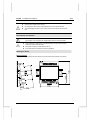
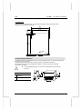
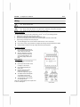
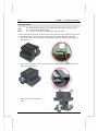
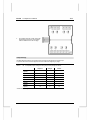
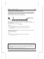
IO-AI8 I/O Expansion Module 8 Analog Inputs The IO-AI8 is an I/O Expansion Module that can be used in conjunction with specific Unitronics OPLC controllers. The module offers 8 analog inputs. The interface between the module and the OPLC is provided by an adapter. The module may either be snap-mounted on a DIN rail, or screw-mounted onto a mounting plate. Component identification 1 Module-to-module connector 2 Communication status indicator 3 Input connection points, AN4 to AN7 4 Input status indicators 5 Module-to-module connector port 6 Input connection points, AN0 to AN3 Before using this product, it is the responsibility of the user to read and understand this document and any accompanying documentation. All examples and diagrams shown herein are intended to aid understanding, and do not guarantee operation. Unitronics accepts no responsibility for actual use of this product based on these examples. Please dispose of this product in accordance with local and national standards and regulations. Only qualified service personnel should open this device or carry out repairs. User safety and equipment protection guidelines This document is intended to aid trained and competent personnel in the installation of this equipment as defined by the European directives for machinery, low voltage, and EMC. Only a technician or engineer trained in the local and national electrical standards should perform tasks associated with the device’s electrical wiring. Symbols are used to highlight information relating to the user’s personal safety and equipment protection throughout this document. When these symbols appear, the associated information must be read carefully and understood fully. Unitronics Symbol Caution Meaning Description Danger The identified danger causes physical and property damage. Warning The identified danger can cause physical and property damage. Caution Use caution. Failure to comply with appropriate safety guidelines can result in severe personal injury or property damage. Always exercise proper caution when working with electrical equipment. 1 IO- A I8 1/1 1 I/O Expansion Module Check the user program before running it. Do not attempt to use this device with parameters that exceed permissible levels. To avoid damaging the system, do not connect / disconnect the device when the power is on. Environmental Considerations Do not install in areas with: excessive or conductive dust, corrosive or flammable gas, moisture or rain, excessive heat, regular impact shocks or excessive vibration. Leave a minimum of 10mm space for ventilation between the top and bottom edges of the device and the enclosure walls. Do not place in water or let water leak onto the unit. Do not allow debris to fall inside the unit during installation. Mounting the Module DIN-rail mounting 44.5mm (1.75") 93mm (3.66") Snap the device onto the DIN rail as shown below; the module will be squarely situated on the DIN rail. 3.5mm (0.137") 1 4m m (0.55") 2 60mm (2.362") 80mm (3.15") Unitronics 1/1 1 IO- A I8 I/O Expansion Module Screw-Mounting The figure below is not drawn to scale. It may be used as a guide for screw-mounting the module. Mounting screw type: either M3 or NC6-32. 85mm (3.346") 93mm (3.66") 5.8mm (0.228") 4mm (0.16") 80mm (3.15") 68.4mm (2.693") 4mm (x2) (0.16") Connecting Expansion Modules An adapter provides the interface between the OPLC and an expansion module. To connect the I/O module to the adapter or to another module: Push the module-to-module connector into the port located on the right side of the device. Note that there is a protective cap provided with the adapter. This cap covers the port of the final I/O module in the system. To avoid damaging the system, do not connect or disconnect the device when the power is on. 1 2 Component identification 1 Module-to-module connector 2 Protective cap Unitronics 3 IO- A I8 1/1 1 I/O Expansion Module Wiring Do not touch live wires. Unused pins should not be connected. Ignoring this directive may damage the device. Do not connect the ‘Neutral or ‘Line’ signal of the 110/220VAC to the device’s COM pins. Double-check all wiring before turning on the power supply. Wiring Procedures 2 2 Use crimp terminals for wiring; use 26-12 AWG wire (0.13 mm –3.31 mm ) for all wiring purposes. 1. 2. 3. 4. Strip the wire to a length of 7±0.5mm (0.250–0.300”). Unscrew the terminal to its widest position before inserting a wire. Insert the wire completely into the terminal to ensure that a proper connection can be made. Tighten enough to keep the wire from pulling free. To avoid damaging the wire, do not exceed a maximum torque of 0.5 N·m (5 kgf·m). Do not use tin, solder, or any substance on stripped wire that might cause the wire strand to break. Install at maximum distance from high-voltage cables and power equipment. I/O Wiring—General Input or output cables should not be run through the same multi-core cable or share the same wire. Allow for voltage drop and noise interference with input lines used over an extended distance. Use wire that is properly sized for the load. Analog Inputs Shields should be connected at the signal source. Inputs may be set as either current, or voltage. To set an input Use the appropriate wiring as shown near. Open the device and set the jumpers according to the instructions beginning on page 5. The adapter and the COM signals of the analog inputs must be connected to the same 0V signal. The COM signals of each channel are internally shorted. When set to current/voltage, each 2 inputs share a common COM signal. 4 Unitronics 1/1 1 IO- A I8 I/O Expansion Module Opening the Device Before opening the device, touch a grounded object to discharge any electrostatic charge. Avoid touching the PCB board directly. Turn power off and disconnect all leads before opening the device. In order to change the jumper settings of a specific input, first open the device by prying off its back, using the blade of a flat-bladed screwdriver. The insertion points for the screwdriver are located on both sides of the module. 1. Open the first side of the device by inserting the blade between the 2 plastic moldings as shown below, then gently pushing up. 2. Taking care not to damage the cable, open the other side of the device by inserting the blade where shown below, then gently pushing up. 3. Gently remove the top of the device as shown. Unitronics 5 IO- A I8 4. 1/1 1 I/O Expansion Module The jumpers are shown at right. Change the jumper settings as required, in accordance with the tables shown on the next page. Jumper Settings The tables below show how to set a specific jumper to change the functionality of a specific input. To open the device and access the jumpers, refer to the instructions beginning on page 5. Caution Incompatible jumper settings and wiring may severely damage the device. Jumper # Voltage* Current Input 0 2 A B Input 1 4 A B Input 2 6 A B Input 3 8 A B Input 4 10 A B Input 5 12 A B Input 6 14 A B Input 7 16 A B * Default factory setting. 6 Unitronics 1/1 1 IO- A I8 I/O Expansion Module IO-AI8 Technical Specifications Max. current consumption Typical power consumption Status indicator (RUN) Analog Inputs Number of inputs Input range Input type Conversion method Normal mode Resolution at 0-10V, 0-20mA Resolution at 4-20mA Conversion time Fast mode Resolution at 0-10V, 0-20mA Resolution at 4-20mA Conversion time Input impedance Isolation Absolute maximum rating Linearity error Error limits Status indicators (OUT OF RANGE) Environmental Operating temperature Storage temperature Relative Humidity (RH) Dimensions (WxHxD) Weight Mounting 40mA maximum from the adapter’s 5VDC 0.2W@5VDC Green LED: —Lit when a communication link is established between module and OPLC. —Blinks when the communication link fails. 8 (single-ended) See Note 1. 0-10V, 0-20mA, 4-20mA. See Note 1. Either Normal or Fast mode, according to the filter type selected in software settings Voltage to frequency 14-bit (16384 units) 3277 to16383 (13107 units) 100mSec minimum per input 12-bit (4096 units) 819 to 4095 (3277 units) 25mSec minimum per input >400KΩ—voltage 500Ω—current None ±15V—voltage ±30mA—current 0.04% max of full scale 0.4% of input value Red LEDs—Lit when the corresponding input is receiving current or voltage in excess of the input range. See Note 5. IP20/NEMA1 0° to 50°C (32 to 122° F) -20° to 60°C (-4 to 140° F) 5% to 95% (non-condensing) 80mm x 93mm x 60mm (3.15 x 3.66 x 2.362”) 150g (5.3 oz) Either onto a 35mm DIN-rail or screw- mounted. Notes: 1. Each input may be set as either voltage (0-10V), or current (0-20mA, 4-20mA) via wiring, jumper and software settings. 2. The voltage or current value of analog inputs can also indicate faults, as shown in the table below. Value: 12-bit (Fast mode) -1 4096 32767 Unitronics Value: 14-bit (Normal mode) -1 16384 32767 Input Value Deviates: Slightly below the input range. Slightly above the input range. Greatly above or below the input range. 7 IO- A I8 1/1 1 I/O Expansion Module Addressing I/Os on Expansion Modules Inputs and outputs located on I/O expansion modules that are connected to an OPLC are assigned addresses that comprise a letter and a number. The letter indicates whether the I/O is an input (I) or an output (O). The number indicates the I/O’s location in the system. This number relates to both the position of the expansion module in the system, and to the position of the I/O on that module. Expansion modules are numbered from 0-7 as shown in the figure below. Adapter 0 1 2 3 4 5 6 7 Expansion module identification number The formula below is used to assign addresses for I/O modules used in conjunction with the OPLC. X is the number representing a specific module’s location (0-7). Y is the number of the input or output on that specific module (0-15). The number that represents the I/O’s location is equal to: 32 + x • 16 + y Examples Input #3, located on expansion module #2 in the system, will be addressed as I 67, 67 = 32 + 2 • 16 + 3 Output #4, located on expansion module #3 in the system, will be addressed as O 84, 84 = 32 + 3 • 16 + 4. EX90-DI8-RO8 is a stand-alone I/O module. Even if it is the only module in the configuration, the EX90-DI8RO8 is always assigned the number 7. Its I/Os are addressed accordingly. Example Input #5, located on an EX90-DI8-RO8 connected to an OPLC will be addressed as I 149, 149 = 32 + 7 • 16 + 5 The information in this document reflects products at the date of printing. Unitronics reserves the right, subject to all applicable laws, at any time, at its sole discretion, and without notice, to discontinue or change the features, designs, materials and other specifications of its products, and to either permanently or temporarily withdraw any of the forgoing from the market. All information in this document is provided "as is" without warranty of any kind, either expressed or implied, including but not limited to any implied warranties of merchantability, fitness for a particular purpose, or non-infringement. Unitronics assumes no responsibility for errors or omissions in the information presented in this document. In no event shall Unitronics be liable for any special, incidental, indirect or consequential damages of any kind, or any damages whatsoever arising out of or in connection with the use or performance of this information. The tradenames, trademarks, logos and service marks presented in this document, including their design, are the property of Unitronics (1989) (R"G) Ltd. or other third parties and you are not permitted to use them without the prior written consent of Unitronics or such third party as may own them. DSP-EXP-AI8 01/11 8 Unitronics