Download Rinnai FS35 ETR Technical data
Transcript
Flame Fire ETR Electronic Timer and Remote Operating and Installation Instructions Freestanding Royale ETR (Australia) Timberflame FS35 ETR (New Zealand) Table of Contents IMPORTANT Customer Instructions Control Panel Layout Operation Setting the Clock Operating the Timers Error Codes Safety Points Troubleshooting 2 3 5 6 7 8 9 Installation Instructions Location Flueing Gas Connection Log Installation Testing & Commissioning Technical Data Service Contact Points Wiring Diagram Installation Checklist Installer Details 10 11 11 12 13 14 14 15 16 16 This appliance shall be installed in accordance with: • Manufacturers Installation Instructions. • Local Gas fitting regulations. • Municipal Building codes. • Gas Installation Code AG5601 / AG601 - NZ 5261. • Any other relevant statutory regulation. • This appliance must only be installed, serviced and removed by an authorised person. • For Australian installation, this appliance must be installed with the supplied wire dressguard. 
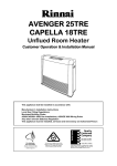
CONTROL PANEL LAYOUT TIME/TEMP. Display Shows either the time of day, temperatures or coded error messages. LOCK Button Indicates lock function CLOCK ADJUSTMENT AND TIMER INDICATORS Indicates that clock or dual timer programme is being set. Flame Function Med. High heat setting and overides thermostat TIMER Indicator Indicates that TIMER 1 or TIMER 2 has been selected to operate. TIME / TEMP. Adjustment Increases or decreases the temperature setting as well as changing hours or minutes. ON/OFF Button Main Switch for turning ON/OFF. AUTO OFF When ON, Thermostat turns heat down to OFF. When OFF, Thermostat turns heat down to LOW. OVERRIDE Temporarily changes operation from ON to OFF or OFF to ON, until next programmed setting is reached. 2 OPERATION • TO OPEN THE CONTROL PANEL Lift lightly in the centre of the lid where there is a catch. The control panel lid will then open backward to an angle. • TURNING ON Press the ON/OFF button to operate the heater. The ON indicator will glow green. The spark generator will be heard before the burner ignites and the ON indicator glows red, indicating that the heater is alight. When the heater warms up, the fan will automatically start. If the heater does not ignite on initial use, this may be due to air remaining in the gas supply line. The spark generator will only continue for 15 seconds. After this it will be necessary to press the ON/OFF button OFF, then ON again. • TURNING OFF Simply press the ON/OFF button to switch off the heater. The ON indicator light will go out. The fan will continue to operate for several minutes after the burner has gone out in order to cool the appliance. Do not unplug the appliance while the fan is running. DO NOT turn off by unplugging at the power point. The fan will continue to run until the appliance cools. • ROOM TEMPERATURE ADJUSTMENT The room temperature and pre-set temperatures can only be displayed and adjusted when the heater is running. Press the “▲“ button to increase the temperature setting or “▼“ button to decrease the temperature setting. The temperatures can be preset to: a) [L] low (about 10°C) b) [16°C] to [26°C] in 1°C steps c) [H] (continuously high) If the heater does not ignite then the pre-set temperature may not be set to a setting which is higher than the room temperature. The ON indicator will change colour from red to green when the heater reaches the pre-set temperature and stops running. • LOCK The LOCK function will help to prevent accidental operation as well as small children from altering the controls. To operate the lock simply press the LOCK button. The function is activated immediately and the LOCK indicator will glow. To deactivate the LOCK simply press the LOCK button for 3 seconds and the LOCK indicator will go out. The LOCK can be deactivated at any time in this way. During normal operation the LOCK may be activated and all controls, other than the OFF switch, will be locked. Deactivating the LOCK releases the controls. If the LOCK is activated whilst the heater is turned OFF, then all functions will be locked. If the heater is turned OFF while the LOCK is activated, it cannot be turned ON again until the LOCK is deactivated. • FLAME To operate the Flame function, simply press the FLAME button. This function will automatically override the thermostat and set the heater to a default Medium High heat setting for full visual flame effect. • AUTO OFF To operate the Auto Off function, simply press the Auto Off button. When the Auto Off function is ON, the indicator light will flash and the thermostat will turn the burners down to the OFF heat setting when the selected temperature is reached. When the Auto Off function is OFF, the indicator light will go Off and the thermostat will turn the burners down to the LOW heat setting when the selected temperature is needed. 3 • OVERRIDE This function is intended to be used to manually override the current operation of the heater. For example; If the heater is in standby mode (ie. between finishing time and starting time of a Timer), and the OVERRIDE button is selected, then the heater will begin to operate and heat the room. To operate the OVERRIDE simply press the OVERRIDE button. The OVERRIDE indicator will flash. To manually deactivate the OVERRIDE simply press the OVERRIDE button again. The OVERRIDE indicator will go out, and the heater will return to standby mode. The heater will continue to operate on OVERRIDE until the OVERRIDE button is pressed again, or one of the Timers takes over the operation of the appliance. This means that the OVERRIDE mode will automatically drop out if a programmed starting time is reached. The appliance will then return to operating at times programmed into the Timer(s). • REMOTE CONTROL Remote Control will not turn heater ON if Timer(s) have been selected. To manually operate when Timer(s) are not selected, simply press the ON or OFF button. To alter the temperature at anytime while the heater is operating, simply press the “▲“ or “▼“ buttons. ON BUTTON Operates the heater manually. TO REPLACE BATTERY Simply open the back of the remote control and replace Lithium battery. TYPE: CR 2032 OFF BUTTON Stops heater manually. TEMPERATURE ADJUSTMENT Increases or decreases the temperature setting. BATTERY Power source for operating remote control Some fluorescent lights may interfere with the transmission of remote control signals, in this case changing the position from which you are operating the remote control may help. Avoid getting the remote control wet, or dropping it. The remote control works within 5 metres and an angle of 40° to the receiver on the heater. Only use the battery type specified. (CR2032). Remove battery if control is not going to be used for a long period. This will help avoid damage from leaking batteries. If the Timer(s) have been selected, and the heater is in standby mode, and the OFF button on the Remote Control is pressed, the Timer(s) will be deactivated. 4 SETTING THE CLOCK pTR • SETTING THE CLOCK When the appliance is first plugged in or after a power failure, the Digital Display will show --:-- As an example, let’s set the clock to 10:35 am: Press the SET TIMES button once, the Clock indicator will flash. Press and hold the “▲“ button; the minutes will begin to change first, then the time will change by whole hours. Release the button when AM 10:00 shows on the Digital Display. Confirm that you have selected AM, a small indicator on the left hand side of the Digital Display indicates the AM setting. Press and hold the “▲“ button again, release the button when AM 10:35 shows. If you go past AM 10:35, then the “▼“ button can be used to change the time settings in reverse. Press the Timer Set button five times to lock in and complete setting the time. The Clock and Timer indicators will go out. A small indicator on the Digital Display will flash to show that the clock is operating. • PROGRAMMING THE ON / OFF TIMERS Before programming the Timers you must ensure that the clock has been set to the correct time. As an example, let’s program Timer 1 to heat the room by 7:10am and finish at 9:00am. Press the Set Times button twice. The Digital Display will show AM 6:00. Timer 1 indicator will flash. Press the “▲“ button until AM 7:00 appears, release the button, then press it again until AM 7:10 appears. (Press the “▼“ button if you go past AM 7:10.) Press the Set Times button again, the Timer 1 OFF indicator will flash. Press the “▲“ button until AM 9:00 appears. (Press the “▼“ button if you go past AM 9:00.) Press the Set Times button three times to lock in the program time. The Digital Display will show the current time. A small indicator on the Digital Display will flash to show that the Display has returned to the clock. Timer 2 is programmed in the same way, remember to ensure that the Timer 2 indicator is flashing when you program in the desired setting. The Timers can be programmed to operate for any two periods in any 24 hours. Turn to the next page to operate the dual timer. The programmed time must be selected and locked-in within one minute of the On Timer indicators flashing otherwise the programmed times will not be retained in the system memory. 5 OPERATING THE TIMERS • OPERATING THE TIMERS Before operating the Timer(s), the clock time must be correct and a starting time and finishing time for the Timer(s) must be programmed. See page 5. The two Timers operate in the same way. This heater does not commence operation at the programmed starting time. It will attempt to heat a room by the programmed starting time. See Pre-heat page 6, for further explanation. To select the Timer(s) to commence heating. Check the time shown on the Digital Display is correct. Check the ON and OFF times, for both Timers if necessary. Press the ON/OFF button to operate the heater. The ON indicator will glow green and the heater will begin to operate. Select the desired temperature setting. Press the Timer 1 and/or Timer 2 button(s). The timer indicator(s) will glow and the heater will remain on standby until one hour prior to the time programmed into the selected Timer(s) is reached. When this time is reached, the Timer indicator will flash and the heater will operate. The ON indicator glows red when the heater commences operation. • SET AND FORGET OPERATION Your heater can be operated to alternate between Timers automatically during cold weather by selecting Timer 1 and Timer 2 together. Both Timer indicators will glow. The appliance will remain on standby at intervals between the programmed finishing and starting times of each Timer. While the heater is operating during programmed intervals the Timer indicator will flash. If there is a power failure, the system memory will retain the Timer programs, and the clock will stop at the time the power goes off. The clock will start again when the power comes back on, but the time will be slow by the duration of the power failure. To set the clock to the correct time after the power has come back on, simply follow the instructions on page 5. • PREHEAT This function operates automatically in conjunction with either of the timers. When a timer is selected, the heater may operate anywhere within an hour prior to the programmed starting time of the timer. The preheat function will attempt to preheat the room by the programmed ON time. This function is called pre-heat due to the way it operates. The room temperature is sensed one hour before reaching the programmed time of either timer. The temperature differential at the time of sensing the room governs how long before the program ON time the microcomputer will operate the heater and ignite the burner. SERVICE Rinnai has a service and spare parts network with personnel who are fully trained and equipped to give the best service on your Rinnai appliance. If your appliance needs service, please ring one of the service contact numbers on page 14 of this booklet. Rinnai recommends that this appliance be serviced every 2 years. 6 ERROR CODES • ERROR CODE MESSAGE The Flame Fire ETR has the ability to check its own operation continuously. If a fault occurs, an Error Message will flash on the Digital Display of the control panel. This assists with diagnosing the fault, and may enable you to overcome a problem without a service call. Please quote the code displayed when enquiring about service. Error Code Probable Cause Comments 11 Ignition Failure Check gas is turned on. Service call if repeated. 12 Flame Failure Check gas is turned on. Service call if repeated. Overheat Service call. Room Overheat Lower room temperature to less than 40ºc. 31 Room temperature Sensor Faulty Service call. 32 Room temperature Sensor Faulty Service call. 33 Overheat temperature Sensor Faulty Service call. 14 16 Faulty ON / OFF Switch Service call. Faulty Solenoids Service call. 72 Faulty Flame Rod Service call. 73 Communication error Turn heater OFF, then ON again. 70 71 99 --:-- Flue Block Service call. Power Failure Turn heater OFF, then ON again. In all cases, you may be able to clear the Error Message simply by turning the heater OFF, then ON again. If the Error Message still remains or returns on the next operation, please contact your nearest service contact and arrange for a service call. 7 SAFETY POINTS Do not restrict the warm air discharge by placing articles in front of the heater. This appliance must not be used for any purpose other than heating. Do not spray aerosols whilst the heater is operating. Most aerosols contain butane gas, and can be a fire hazard if used near the heater when it is in use. Young children should be supervised at all times. Hand or body contact with the louvres should be avoided. Do not allow young children or the infirm to sleep directly in front of the heater. Do not allow anyone to sit on or lean against the appliance. Do not allow curtains or other flammable or combustible materials to come into contact with the heater. Do not allow anyone to post articles through the louvres. DO NOT PLACE ARTICLES ON OR AGAINST THIS APPLIANCE. DO NOT USE OR STORE FLAMMABLE MATERIALS NEAR THIS APPLIANCE. DO NOT SPRAY AEROSOLS IN THE VICINITY OF THIS APPLIANCE WHILST IT IS IN OPERATION. 8 TROUBLESHOOTING SOLUTION SYMPTOM CAUSE Burner will not light No power present Ensure power cord is plugged in and turned on No gas present Ensure gas supply is turned on Power cut Air in gas pipe Re-ignite after power is restored Purge air (installer) Ignition Failure Repeat lighting procedure (refer page 3) Smell of gas Leaking gas Turn gas off at meter and call installer Fan not working Heat switch not activated Allow heater to run on HIGH for 15 minutes minimum. Fan not turned on Ensure appliance fan switch is in ON position Small soot deposit Normal operation No action required Severe soot deposit forming on Glass or Logs Inadequate Flue System Log Misalignment Incorrect Gas Pressure Call Rinnai Service Dept./Agent Condensation on Glass Normal operation Allow heater to warm up Streaky lines on Glass Normal operation Remove and clean Glass Digital Error Message on Control Panel Electronic fault detected See Error Messages Page 7 • NOTE If you have any other faults or problems, please refer to your Installer. • CLEANING INSTRUCTIONS. Before cleaning, ensure the power and gas are turned off and that the heater has cooled down. Do not remove any internal wiring covers. Use only non-abrasive cleaners. Do not use solvent based cleaners. • OUTER CASE The outer case of the heater should be cleaned with a soft, damp cloth. Do not use aerosol polishes to clean the casing while the heater is in operation. • GLASS CLEANING After a period of use the glass panel may require cleaning. When your heater is cold, refer to Page 12 and follow the initial log installation instructions to remove side panels and glass for cleaning purposes. IMPORTANT NOTE. This appliance is designed with luminous flames and may exhibit slight carbon deposits. 9 LOCATION When positioning the heater, the main points governing the location are: 1. Flueing. 2. Warm air distribution. 3. The heater must not be installed where curtains or other combustible materials could come into contact with it. In some cases, curtains may need restraining. See below for minimum clearances required. 4. The heater is not designed to be built into bookcases or shelves or any combustible opening. 5. Check that room ventilation complies with local regulations. 6. Check that an EARTHED power point is within 1500mm. of the right hand side of the heater. 7. The heater does not require any additional hearth or floor protection. 10 FLUEING • This heater requires a minimum 3m. flue. • Position the heater. • Suspend a plumbline from the ceiling to the centre of the flue socket. • Mark the centre of the flue in the ceiling. • Make a small hole in the ceiling and double check that the flue system will be at least 25 mm clear of combustible materials. • Cut the hole for the flue. • Fit the ceiling plate, flue and decorative cover. The decorative cover must be able to slide up to give access to the flue spigot. The inner flue must be supported independently of the heater but allowing sufficient movement to allow connections to and disconnections from the flue spigot. GAS CONNECTION • RUN GAS SUPPLY For pipe sizing, refer to your local gas installation codes. Copper supply should be run leaving a flared connection at the position shown. PURGE SUPPLY OF AIR AND SWARF. All foreign materials such as filings must be purged from the gas supply, as they may cause the gas valve to malfunction. Connect and tighten union. On completion of work, check for gas leaks. 11 LOG INSTALLATION The logset is packed inside the heater and the packaging must be removed prior to installing the logset in its correct position. • Open both side panels. • Remove fastenings on both sides of the top glass retainer. Lift retainer away from heater. • Loosen screws on bottom glass retainer. Carefully lift glass out of bottom channel. • Carefully remove log packaging. The logset consists of a Main Log which has four pins on the top, for the location of the Top and Right Logs and two holes underneath for location onto the pins inside the heater. Place the logset into the heater ensuring that the locating pins enter the two locating holes on the bottom vvvvv face of the logset, if not already attached. Carefully position the Top Log and the Right Log on the locating pins of the Main Log as shown. Top Log Right Log Main Log Gently place loose ember bed material in front of the front log. Do not pour as dust particles from the plastic bag may block the burner ports. Level it with a pencil or screwdriver and remove excess material. Note: The ember bed material must be placed after the logs are fitted. If the logs are to be removed for any reason, the ember bed material must be removed first and replaced after the logs are refitted. Any material that prevents the logs sitting flat on the burner top can upset the burning pattern and performance of the heater. • Replace glass and top glass retainer, tighten bottom glass retainer screws. • Note: Fit glass so that the join/gap in the glass seal is at the bottom. • Take care not to damage seals. • Reinstall side panels. Note: When first lighting the heater, the logs need to be burnt in, which may take approximately 2 hours. The flame colour may change after the initial burning in period. 12 TESTING & COMMISSIONING Comple • TESTING PROCEDURE Turn gas supply on and plug the unit into the power supply. (Caution 240V.) • TO CHECK BURNER PRESSURE • Refer to Data Plate. • Remove the wiring cover panel. • Remove test point screw and attach manometer to test point. The test point is on the front side of the gas valve. • Light heater, turn to High heat setting and check pressure. • If adjustments are necessary, the regulator is situated on the front of the gas control. • After checking pressure, turn the unit off, remove manometer and replace test point screw. • Turn the heater on and off a few times to check ignition. • When you are satisfied that the heater is working correctly, reassemble panels. • All burner aeration is factory preset and cannot be adjusted. • If you are unable to get the unit to operate correctly, refer to Troubleshooting on Page 9, before contacting your local service contact as listed on Page 14. • It may take approximately 2 hours for the logs to achieve their full flame pattern and glow. • During the initial burning in period, some smoke and smell may be experienced. The heater should be run on the high position in a well ventilated room until these dissipate. It is the responsibility of the installer to check that under normal operating conditions of the appliance, all flue gases are exhausted to the outside atmosphere and that there is no spillage of combustion gases into the room. Please refer to AS5601 / AG601 clauses 5.13.3.3 • COMMISSIONING • INSTALLATION AND COMMISSIONING CHECKLIST Complete the installation / commissioning checklist and the installer / gasfitter details on page 12 and make sure that this instruction book is left with the customer. • INSTRUCT CUSTOMER ON USE OF UNIT Explain to customer about use and care of unit. Make sure the customer understands the instructions. • EXPLAIN TO THE CUSTOMER Ignition, Adjusting heat level, Fan Switch, Turning “OFF”. The guard on this appliance conforms to AGA. requirements. It is designed to prevent the risk of fire or injury from burns, and no part of it should be permanently removed. IT DOES NOT GIVE FULL PROTECTION TO YOUNG CHILDREN OR THE INFIRM. NOTE: RINNAI RESERVES THE RIGHT TO CHANGE OR MODIFY SPECIFICATIONS WITHOUT NOTICE. 13 Comple TECHNICAL DATA Model: FGL35ETRBN (NG) Australia FGL35ETRBL (LP) Australia FS35ETRN (NG) New Zealand FS35ETRL (Propane) New Zealand Rinnai Inbuilt Radiant/Convector, glass-fronted, ceramic log space heater with forced convection and natural draught flue system. 35 MJ/h Natural Gas and Propane. Rinnai Electronic Control Valve. Ceramic Logs, Ember Bed and Heat Burner. 15mm. Copper Flare Connection. Natural Gas 0.95 kPa; Propane 2.40 kPa. Natural Draught. An approved 100mm. cowl must be fitted to all installations. Electronic Spark. 230/240v. 50Hz unit is supplied with 3 pin plug and supply lead, replace only with Rinnai P/N 90179599(Aust.) 6765B(NZ). Tangential 2 Speed, Watt Rating 90W. Bottom R/H side of pillar. Description: Input: Gas Control: Burner: Gas Inlet: Test Point Pressure: Flue: Flue Termination: Ignition: Power Supply: Fan: Data Plate: SERVICE CONTACT POINTS RINNAI AUSTRALIA PTY. LTD. ACN. 005 138 769 Helpline: 1300 366 388 Mon.-Fri (8.30am-5.30pm EST) (Cost of a local call - higher from mobile or public phones) Head Office: Vic./Tas. Sales Service Internet: www.rinnai.com.au Email: [email protected] 10-11 Walker St. Braeside, Vic. 3195 Tel.(03) 9271 6625 Fax.(03) 9271 6622 Tel.(03) 9271 6666 Fax.(03) 9271 6611 Tel.(03) 9271 6699 Fax.(03) 9271 6688 QLD: 1/6 Booran Drive, Logan Central, Qld. 4114 Tel. (07) 3209 4622 Fax. (07) 3209 4722 WA: 18 Belgravia St. Belmont, WA. 6104 Tel. (08) 9478 3355 Fax. (08) 9277 2531 NSW/ACT: 62 Elizabeth St. Wetherill Park, NSW 2164 Tel. (02) 9609 2888 Fax. (02) 9729 5260 SA./NT: 140 Days Rd. Ferryden Park, SA. 5010 Tel. (08) 8345 0292 Fax. (08) 8345 4760 RINNAI NEW ZEALAND LTD. 691 Mt. Albert Rd. Royal Oak, Auckland, NZ. PO Box 24-068 Tel. (09) 625 4285 Fax. (09) 624 3018 24 Hr. Service Tel. 0800 746624 (0800 Rinnai) Internet: www.rinnai.co.nz Email: [email protected] 14 WIRING DIAGRAM 15 INSTALLATION / COMMISSIONING CHECKLIST (To be completed by certified Gas Installer) Model: ____________________ NO YES 1. Was a fireplace inspection carried out? (ie. clearances, combustibles etc.) 2. Was chimney inspected? 3. Did chimney require flue liner system to be installed? If NO, did chimney meet specified criteria as per manual? 4. Has specified gas pressure been set? 5. Are decorative logs located correctly on pins? 6. Have ember granules been placed and free of dust and powder? 7. Has appliance been sealed around the fireplace? 8. Has the appliance been commissioned? 9. Is the end-user fully aware of operating procedure? INSTALLER / GASFITTER DETAILS Company Name: ____________________________________________________________________ Gasfitters Name: ____________________________________________________________________ Address:____________________________________________________________________________ ____________________________________________________________________________ Phone: __________________________ Mobile: ____________________________ Certificate of Compliance / Certification Number: ______________________________________ Signed: _________________________________ Date: ______________________________ 16 Part Number 7567