1
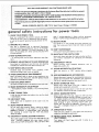
Save This Manuat
For Future Reference
MODEL NO.
/
e
/
113.243300
SAW ONLY
/
/
/ '/
/
MODEL NO.
/
/ /
\
113.243311
.\
SAW WITH LEGS
AND MOTOR
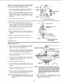
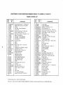
Serial
Number
Model and serial
number may be found
at the right-hand
of the frame,
side
You should record both
model and serial number
I
in a safe place for
future use.
12-iNCH
SANDER
CAUTION:
Read
GENERAL
ADDITIONAL
= assembly
and
SAFETY
• operating
INSTRUCTIONS
carefu|ly
Sold
by
Part No. 69185
SEARS,
ROEBUCK
• repair
parts
AND
Chicago,
CO.,
[L.
60684
U.S.A.
Printed in U.S.A.
FULL ONE YEAR WARRANTY
If within
one year from the date of purchase,
or workmanship.
Sears
will repair
it, free
WARRANTYSERVICE
IS AVAILABLE
CENTER/DEPARTMENTTHROUGHOUT
THiS
WARRANTY
This warranty
to state.
APPLIES
gives
SEARS.
general
ONLY
ON CRAFTSMAN
this Craftsman
Band Saw fails due to a defect
THiS
PRODUCT
THE
IS IN
legal rights, and you may also have other
ROEBUCK
AND
safety
in materia!
698/731A,
instructions
Sears Tower,
for
NEARESTSEARS
USE
you specific
CO..
SAW
of charge.
BY SIMPLY
CONTACTING
THE UNITED
STATES
WHILE
SAND
iN THE
UNITED
rights which
Chicago,
SERVICE
STATES
vary from
state
IL 60684
power
tools
1. KNOW YOUR POWER TOOL
mask if cutting
(plugs or muffs)
Read and understand
the owner's manua
and labels
affixed to the tool. Learn its a pplication
ana limitations
as well as the specific potential
hazards peculiar to this
13. SECURE WORK
toot.
2. GROUND
This
toot
Use clamps or a v=se to hold work when practical.
It's
safer than using your hand, frees both hands to operate
tool.
ALL TOOLS
is equipped
with
an
approved
3-conductor
cord and a 3-prong grounding
type plug to fit the proper
grounding
type receptacle.
The green conductor
in the
cord is the grounding
wire. Never connect
the green w_re
to a live terminal.
3. KEEP GUARDS
- in working
ment.
14. DON'T OVERREACH
Keeo orooer
and in proper
adjustment
Keep
once.
and align-
KEYS AND WRENCHES
17. AVOID
Cluttered
areas and benches
mvite
accidents.
must not be slippery due to wax or sawdust.
DANGEROUS
Floor
Make
7. KEEP CHILDREN
should
ENVIRONMENT
MAKE
WORKSHOP
C MILD-PROOF
-- with
padlocks,
switches
master
Consult
Follow
switch
starter
Do
9. DON'T FORCE TOOL
rate for which
or attachment
to do
a job
it was not
11. WEAR PROPER APPAREL
Do not wear loose clothing, gloves, neckties or jewelry
(rings,
wristwatches)
To get caught iF moving
parts.
NONSLIP
footwear
is recommended.
Wear protective
hair covering
to contain
long hair. Roll long sleeves
above the elbow.
GOGGLES
before
p[uggmg
accessories.
accessories.
may cause hazards,
not
store
materials
above
is t_pped
or near me tool
to stand on the tool
or if the
such that
to reach them.
PARTS
Before further use of the tool, a guaro or other part that
=s damaged should be carefully
checked to ensure that _t
will operate properly
and perform
its mtended
function.
Check for alignment
of moving parts, binding
of moving
parts, breakage
of parts, mountmg,
and any other conditions
that may affect
its operation
A guard or other
cart that
s damaged
should
be properly
reoaired
or
replaced.
TOOL
Don't
force tool
designed for,
13osltion
ACCESSORIES
accessories
20. CHECK DAMAGED
and safer at the
as
STARTING
is an "OFF"
Serious injury could occur if the tool
cutting tool is accidentally
contacted.
or by removing
sucn
19. NEVER STAND ON TOOL
work area_
it _snecessary
It will do the job better
it was designed.
accessories
the owner's manual for recommended
the instructions
that accompany
the
The use of improper
keys,
12. USE SAFETY
ACCIDENTAL
sure
18. USE RECOMMENDED
AWAY
be kept a safe distance from
changing
In.
Don't
use power tools in damp or wet locations
or expose mere to rain. Keep work area well lighted, Provide
adequate surrounding work space,
10. USE RIGHT
oerformchangmg
TOOLS
before
servicing;
when
blades, bits, cutters, etc.
5. KEEP WORK AREA CLEAN
8,
at all times.
tools sharp and clean for best and safest
Follow
mstructions
for luOncatlng
and
16. DISCONNECT
Form habit of checking
to see that keys and adjusting
wrenches are removed from toot before turning
it on
All visitors
and balance
TOOLS WiTH CARE
accessories.
4. REMOVE ADJUSTING
0. AVOID
footing
15. MAINTAIN
IN PLACE
oraer,
operation
is dusty,
and ear protectors
during extended
periods of operation.
21. DIRECTION
OF FEED
Feed work into a blade or cutter against the direction
rotation
of the blade or cutter only.
22. NEVER LEAVETOOL
UNATTENDED
(Head Protection)
Wear safety goggles (must comply with ANSI Z87.1) at all
times. "Everyday eyeglasses only have impact resistant
lenses, they are NOT safety glasses." Also. use face or dust
Turn
power off.
complete stop.
2
Don't
o!
RUNNING
leave tool
until
it comes to a
Safety
is a combination
of
alertness
at all times when
h. When cutting
a large piece
is supported
at table height.
operator
common
sense and
the band saw is being used.
i. Hold the work
FREEHAND
WARNING:
FOR YOUR OWN SAFETY,
DO NOT
ATTEMPT TO OPERATE YOUR BAND SAW UNTIL mT
tS COMPLETELY
ASSEMBLED
AND INSTALLED
ACCORDBNG TO THE INSTRUCTIONS
, .. AND UNTSL
YOU
HAVE
READ
AND
UNDERSTOOD
THE
FOLLOWING:
2. Getting
Safety
Instructions
To Know Your
Band Saw/Sander
3. Basic Band Saw Operation
4. Maintenance
5. Stability
for Power Tools
......
........
....................
2
18
21
...............................
of Machine
m.
Location
1.
7. Protection:
a.
d.
e.
cut pieces
of
Face, Ears, Body
material
too
small
to hold
f.
o.
Never operate the band saw with
frame cover
with
protective
cover on the unused shaft end
the motor removed.
or
of
Do
on
blade
runs downward
toward
the table
Always
sanding
adjust tension
correctly
belt being used...
for
the
blade
q.
8.
perform
layout,
assembly,
the cutting
tool
Turn
saw "OFF"
before
installing
attachment.
or setup work
is rotating.
and remove
or removing
plug from
power
an accessory
or
Should any part of this band saw be missing, or bend, or
fail in any way, or any electrical
component
fail to
perform
properly,
shut off power switch,
and remove
power
supply
cord
from
power
supply.
damaged,
missing, and/or
failed parts before
operation.
or
g.
g. Always adjust the upper blade guide and blade guard
to just clear the workpiece
to protect
the operator,
to keep blade breakage to a minimum,
and to provide
maximum
support for blade.
not
the table while
in the right direction.
Always
adjust tracking
wheel
correctly
so that
the blade does not run off the
wheels.
in the
while
Never leave the band saw work area with the power
on, before the machine
has come to a complete
stop, or without
removing
and storing
the switch
key.
p,
Never turn your band saw "ON"
before clearing the
table
of all Objects
(tools,
scraps of wood, etc.)
except for the workpiece
and related feed or support
devices for the operation planned.
or wedge
by hand
n.
by
Avoid awkv_ard
hand positions
where a sudden slip
could
cause a hand to move into the blade or the
sanding belt.
Make sure the
Turn off the band saw . . . remove plug from
povver source outlet
. . . remove
cover from
band saw. Insert a screwdriver
kerf . . . rotate
the wheels
backing up the workpiece.
use only.
Wear safety goggles that comply
with ANSI Z87.1 and
a face shield if operation
is dusty. Wear ear plugs or
muffs during
extended
periods of operation.
Do not
wear gloves..,
roll long sleeves above the elbow.
b. Do not
hand.
c.
Eyes, Hands,
for indoor
DO NOT
When
backing
up the workpiece,
the blade may
bind in the kerf (cut} . . . this is usually caused by
sawdust clogging
up the kerf or because the blade
comes out of the guides. If this happens:
The band saw should be positioned so neither the operator nor a casual observer is forced to stand in line with
the blade. This band saw is intended
table.
Use caution when cutting off round material such as
dowel rods, or tubing. They have a tendency
to roll
while being cut causing the blade to "bite".
Always
use a "V" block, or clamp round material to a miter
gauge.
22
Your band saw must be bolted
securely to a stand or
work bench. In addition,
if there is any tendency
for the
band saw to tip over or move during certain operations
such as cutting long heavy boards, bolt your bandsaw to
the floor.
6.
the
sure it
Use caution
when cutting
off
material
which
is
irregular
in cross section
which
could
pinch the
blade
before
the cut is completed.
A piece of
molding
for example
must lay fiat on the table and
not be permitted
to rock while being cut.
k.
General
against
make
Do not feed the material
too fast while cutting,
Only feed the material
fast enough so that the blade
wiil cut, Keep fingers away from the blade,
PAG E
1.
firmly
of material,
Think
Replace
resuming
Safety.
Safety
alertness
is a combination
whenever
the
of operator
band
common
saw/sander
sense and
is n operation.
additional safety instructions
for band saw/sander
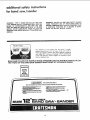
WARNING:
DO NOT ALLOW FAMiLIARiTY
(GAINED
FROM FREQUENT
USE OF YOUR BAND SAW) TO
BECOME COMMONPLACE. ALWAYS REMEMBER THAT
A CARELESS FRACTION OF A SECOND iS SUFFICIENT TO iNFLICT SEVERE iNJURY.
WARNING:
THE 5" BAND SAW PULLEY AND THE
2-I/2" MOTOR PULLEY FURNISHED, WILL RUN THE
BLADE AT APPROXIMATELY
900 RPM (OR 2700
FEET PER MINUTE) WHEN USED WiTH A 1725 RP_
MOTOR. NEVER SUBSTITUTE
THESE PULLEYS TO
iNCREASE THIS SPEED BECAUSE IT COULD BE DANGEROUS.
WEAR
YOUR
The operation
of any power tOOl can result
in foreign
objects
being thrown
into the eyes, which can result in
severe eye aamage. Always
wear safety goggles complying
with ANSi Z87.1 (shewn on Package} before commencing
power tool operation.
Safety Goggles are available at Sears
retail
READ AND
THE FRONT
or catalog stores.
FOLLOW THE INSTRUCTIONS
OF THE BAND SAW/SANDER
APPEARING
ON THE iNSTRUCTiON
PLATE
AND FRONT OF THE BLADE GUARD.
DANGER
ALLOW
TOOL TO
STOP
BEFORE
ADJUSTING
_| BELT
DRIVE
BA D
SAW-
4
SA DE
ON
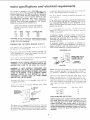
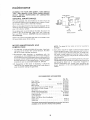
motor specifications
Qnd eledrkai
This machine
is designed
to use a 1725 RPM motor only.
Do not use any motor that runs faster than 1725 RPM. It is
wired for operation
on 110-120 volts, 60 Hz., alternating
current.
(TOOL MUST NOT BE CONVERTED
TO OPERATE
ON 230 VOLT
EVEN
THOUGH
SOME OF THE
RECOMMENDED
MOTORS
ARE
DUAL
VOLTAGE,
CHANGING
TO 230 VOLT
WILL
NOT
CONSERVE
ENERGY
AND
REQUIRES
CHANGING
THE
POWER
CORD PLUG AND MOTOR
RECEPTACLE.
THESE CRAFTSMAN
MOTORS
FOUND
TO BE ACCEP1ABLE
THIS TOOL.
HP
1/2
1/2
1/2
RPM
1725
1725
1725
VOLTS
115
115
115
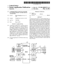
TO POWER SOURCE
This machine
must be grounded
the operator
from electric shock.
while
NO.
OUTLET
in use to
This plug
requires
outlet as shown.
a mating
protect
3-conductor
grounded
type
if the outlet you are planning
to use for this power tool is
of the two prong
type DO NOT REMOVE
OR ALTER
THE GROUNDING
PRONG
IN ANY
MANNER.
Use an
and always
It is recommended
that
rep!ace
the TWO prong
THREE
prong outlet.
CAUTION:
Do not use blower or washing machine motor_
or any motor
with an automatic
reset overload
protector,
as their use may be hazardous.
CONNECTING
is attached to the tool housing at one end and to the ground
prong in the attachment
plug at the other end.
adapter as shown below
_ug to known ground.
HAVE BEEN
FOR USE ON
CATALOG
1278
1279
1289
requirements
connect
the grounding
you have a qualified
outlet
w;th a properly
electrician
grounded
A temporary
adapter
as shown
below
is available
for
connecting
plugs
to 2-prong
receptacles.
The green
grounding
lug extending
from
the adapter
must
be
connected
to a permanent
ground
such as to a properly
grounded
outlet box.
A temporary
adapter
as illustrated
is available
for
connecting
plugs to 2-prong
receptacles.
The temporary
adapter
should
be used only until a properly
grounded
outlet can be installed
by a qualified
electrician,
GROUNDING
LUG
Plug power cord into a 110-120V
properly
grounded
type
outlet
protected
by a 15-amp dual element time delay or
Circuit-Saver
fuse or circuit
breaker.
If you are not sure that your outlet
have it check by a qualified
electrician.
is properly
grounded,
WARNING:
DO NOT PERMIT
FINGERS
TO TOUCH THE
TERMINALS
OF PLUGS
WHEN
iNSTALLING
OR REMOVING
THE
PLUG
TO OR FROM
THE OUTLET.
WARNING:
IF NOT PROPERLY GROUNDED
THIS
POWER TOOL CAN CAUSE AN ELECTRICAL
SHOCK
PARTICULARLY
WHEN USED IN DAMP LOCATIONS
CLOSE TO PLUMBING. IF AN ELECTRICAL
SHOCK
OCCURS
THERE
IS THE
POTENTIAL
OF A
SECONDARY
HAZARD
SUCH AS YOUR HANDS
CONTACTING THE SAW BLADE.
If power cord is worn
it replaced irnmediate!v.
or cut,
If your unit is for use on
that looks like below.
or damaged
less than
150
in any way,
volts
have
it has a plug
3--PRONG
PLUG
3-PRONG
_
I..._""
'_.,,-
,3_
_-_._
_)!_J
-_/
L_
MAKE SURE THIS IS
CONNECTED
TO A
_
"_
2-PRONG
RECEPTACLE
ADAPTER
NOTE:
The adapter illustrated
is for use only if you already
have a propedy
grounded
2-prong
receptacle.
Adapter
is
not allowed
in Canada by the Canadian
Electrical
Code.
The use of any extension
cord will cause some loss of
power.
To keep this to a minimum
and to prevent
overheating and motor burn-out,
use the table below to determine the minimum
wire size (A.W.G.)
extension
co_d. Use
only 3 wire extension
cords which
type
plugs and 3-pole
receptacles
plug.
Extension
Cord
Length
Up to 100 Ft.
PROPERLY
GROUNDED
100
200 Ft,
200-400
Ft,
have 3 prong grounding
which
accept the tools
Wire
Size
A.W.G.
16
14
10
OUTLET,_
CHECK
GROUNDING
PRONG
This power tobl is equipped
with a 3-conductor
cord and
grounding
type plug which has a grounding
prong, approved
by Underwriters'
Laboratories
and the Canadian Standards
Association.
The ground conductor
has a green jacket and
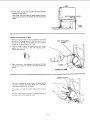
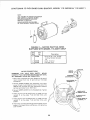
MOTOR
ROTATION
Before checking
motor rotation
make sure key is removed
from shaft. Place the motor on your workbench
or on the
floor.
Standing
clear of the shaft,
plug the cord into a
properly
grounded
outlet.
Notice rotation
of the shaft. If
motor is not turning
counterclockwise,
remove the plug and
contact your Sears store immediately,
tf motor turns counterclockwise
remove
the plug and proceed
on with the
assembly.
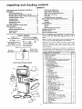
unpackm°n g and checking
contents
CONTENTS
UNPACKING
ASSEMBLY
AND
CHECKING
CONTENTS
.......
Blade Guide
6
Lateral
Assembling
Steel
Legs
........................
Saw/Sander
7
Mounting
Band
on Leg Set
........
8
Installing
Installing
Motor.
Pulley. V-Belt. and Belt Guards 8
Sawdust
Elbow
...................
11
Installing
Table
.............................
12
Installing
Blade
.............................
1 2
Adjusting
the Table
.........................
On-OH Switch
..............................
GETTING
TO KNOW
SAW/SANDER
YOUR
Adjustment
Diagrams
Tilting
...................
17
...................
17
Blade Thrust Bearing Adjustment
............
Guide Bar Lock Screw
......................
17
17
Guide
18
Bar
..................................
Installing Sanding
Attachment
..............
BASIC
BAND SAW/SANDER
OPERATION
20
20
21
17
General
.....................................
Motor
......................................
21
21
BAND
.......................
Recommended
17
................................
Accessories
.................
17
17
TROUBLE
SHOOTING
..........................
REPAIR
PARTS
.................................
17
MOTOR
CONNECTIONS
21
22
24
.......................
2g
=
TOOLS
SMALL
SCREWDRIVER
MEDIUM
NEEDED
_
113.243300
carton
but
Model
in one
113.243311
carton
and
314 INCH
SQUARE
MUST
WRENCH
BE
certain
all
packing
material.
LIllE
ALONG
LIGHT
ON
Saw/Sander
is shippec
complete
NOT
INCLUDE
Steel
Legs or
BOARD
STRAIGHT
EOG£ OIF
eOARD
3/4TRICK
rHle
THIS
EDGE
PERFECTLY
MUST
BE
any
band
until
items
are
packing
materials
and check
and "Table
of Loose
Parts,"
accounted
for,
before
discarding
each
Make
any
parts
are
missing,
do
saw,
plug
the missmg
in the
parts
TABLE
OF LOOSE
not
power
cord
are obtained
attempt
to
assemble
or turn
the
and installed
the
switch
on
correctly.
STRAIGHT
ITEM
A
B
C
D
E
F
G
H
J
A
/C
/
J
/
K
L
Fj
Band Saw/Bander'is
shipped
complete
INCLUDES
Steel
Legs and Motor.
TRUE
If
--_'_,
DeAW
Band
DOES
Separate
all parts
from
item
with
illustration
7/16 INCH WRENCH
3/8 INCH WRENCH
SCREWDRIVER
COMEINATION
Model
in one
Motor.
.
__
SCREWDRIVER
@2 PHILLIPS
18
20
.....
Sawing
.....................................
Sanding
....................................
MAINTENANCE
................................
Adjustment
Knob ...................
Scales
..............................
Table
Adjustment
"15
16
.................................
Tension
Tension
Adjustment
Guide
_M
M
PARTS
Basic Saw Assembly
........................
Owner's Manual
...........................
Saw Table
...............................
I/2 x 52-1n. V-Belt .........................
Carton containing Belt Guard, Belt*Guard Support,
Support Bracket, three Clips and three SelfTapping Screws ..........................
1/2-In. Sanding Belt ........................
I/4-1n Band Saw Blade ......................
Sawdust Elbow
...........................
Loose Parts Bag -1_69139
(Containing the following items:)
Sanding Platen
..........................
Wrench
Table Insert .............................
Pulley, 5"
. .............................
Pulley Motor, 2-1/2"
. .....................
Knob Tension Adj ........................
Tube Clamp
Foam Gasket (Strip)
Loose Parts Bag _69140
(Containing the following
items:)
Key, Sq. 3/16 x 1-1/8"
. ...................
Wing Nut, 1/4-20
........................
Spacer .................................
I
Screw, Truss Hal. 1/4-20 x 1 .................
Hex, Nut 3/8-16
..........................
Flat Washer, 17/64 x 5/8x
1/16
..............
Flat Washer, .380 x 1-9/64 x 7/64
...........
Set Screw Wrench, 1/8"
. ..................
Set Screw Wrench, 3/16"
. .................
Set Screw Wrench, 5/32"
. ................
Loose Parts Bag =;_9141
{Containing
the following
items:)
Switch Key ............................
Lockwasher,
"_
........................
Hex Nut, 6-32
Soc. Hd. Set Screw, 5/16-18
x 3/8"
. ........
Screw, Pen Hd. Ty. "T" 8_32 x 3/8"
. ........
Screw, Pan Hd. Ty. "T"
10-32 x 3/8"
. .......
Screw, Flat Hd. 6-32 x 7/16"
. .............
Cord Clamp ............................
Plate, Alignment
........................
Pointer
...............................
"L'" Bracket ..............................
QTY.
1
1
1
1
2
1
1
1
1
1
1
1
1
1
1
1
1
1
1
1
1
1
1
1
1
1
1
t
1
I
2
2
1
1
1
1
1
THE
FOLLOWBNG
MODEL
I 13,24331
PARTS'
1 ONLY.
ARE
iNCLUDED
WiTH
Description
totem
Qty. 1
I
Nut,
He× Head 1/2-13
A
A
*NutHex
B
"Screw
C
1/4-20
..............
Truss Hd.
Lockwasher,
D
E
F
" Foot,
Motor
1/4-20
x 5/8
1/4 External
.....
8
I
32
1
32
.......
32
Leveling
...............
.....................
Leg .......................
Channel, Support
G
H
..........
..............
J
Stiffener,
Stiffener,
Side ................
End ...................
K
Support,
Motor
HARDWARE
FOR
4
I
...............
MOUNTING
TOOL
i
I
4
2
t
I
2
2
I
1
I
I
F_
& MOTOR
Lockwasher
Ext. 5/16
...........
Nut,
Hex 5/16-18
..............
CA
* Washer
* Bolt,
11/32
Carriage
* Parts Contained
ID
5/16-18
In Loose
A
..............
x 3/4
.......
Parts Bag Part No. 69097
C
B
D
g
N
N
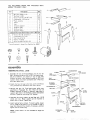
assembBy
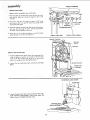
ASSEMBLING
STEEL
LEGS
HEX NUT
SCREW
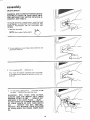
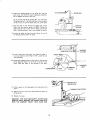
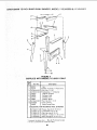
1. Assemble
the
two
(2)
End
Stiffeners
and
the
two
(2)
Side Stiffeners
using four (4) 1/4-20 Truss head screws.
The
End Stiffeners
are placed on top of each Side
Stiffener
as shown. Insert screws through
the 9/32 inch
diameter
holes and attach Iockwashers
and 1/4-20 nuts
and finger
2. Attach
tighten
the
four
using 1/4-20
3. Remove
assembled
Support
supports
and nuts.
nuts.
END
STIFFENER
STIFFENER
SIDE
STIFFENER
!
SIDE STI FFENER
]
CHANNEL
(4) legs to the Side and End Stiffeners
screws, Iockwashers
LOCKWASHER
®_f
._j_/-
"_
..jJ
__
SUPPORT _
;
I
_
CHANNEL
and nuts as shown.
the four
(4) Truss head screws which
were
in Paragraph
No. One. Place the two (2)
Channels as shown,
in position,
align holes in
with holes in the Stiffeners, replace Iockwashers
Tighten all nuts using 7/16" wrench.
LOC KWASH ER -._.___
HEX NUT _
SUPPORT
LEG
l
I/4-20
SCR EW_°_
t
I
LEGS_f"
REW
LEG _
4. Assemble
the motor support to steel legs with 1/4-20
screws and nuts. Motor
support can be mounted
to
either end of stand. Tighten
nuts.
SCREW
5. Install
leveling feet as shown. To level Leg Set, loosen
nut on inside of leg and turn nut on outside to raise or
lower feet. Adjust all four levelers, if necessary, and then
tighten
NOTE:
justment,
MOTOR
SUPPORT
LOCK_/ASHE
nuts on inside of leg.
These
levelers
are
not
intended
for
height
acF
LEVELING
FEET
"_"-_...._
,_
HEX NUT
R
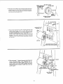
assembly
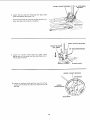
MOUNTING
BAND
SAW/SANDER
ON
LEG SET
LE FT
FOOT \
NOTE: For illustrative purposes, the Band Saw is shown
mounted on the Craftsman Catalog No. 9-22236 Steel *Leg
Set. This Leg Set is included with Model No. 113.243311.
RIGHT
FOOT
CHECK
1. Remove
the
Band
Saw
cover
by
applying
gentle
pressure on the spring tabs and release the top
of the cover by pulling it away from the frame.
procedure for bottom
portion
of cover
NOTE:
Check
Saw as shown.
the bolts
side
portion
Repeat
BOLTS
FOR
TIGHTNE_
which hold the feet to the Band
Make sure they are tight.
o
©
0
2. Place the Band Saw on the Steel Legs, position
as
shown and align the mountmg
holes in the feet of the
Band Saw with those in the END STIFFENERS (marked
with an X in the illustration),
3,
Mount saw to legs using four (4) 5/16-1BXl
" hex head
screws, Iockwashers,
and hex nuts. Tighten screws.
0 o
0 o
°° 0
Oo
©
0
©©
o
FRONT OF
SAW HERE
o
MOTOR
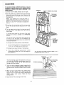
iNSTALLING
AND
BELT
MOTOR,
GUARDS
1. Locate the following
Qty.
PULLEY,
AT
THIS
END
_ARD
SUPPORT
Description
Motor
-L'" Bracket
1
1
1
1
Small Pulley (approx.
Large Pulley (approx.
Woodruff
Key 3/16"'
V-Belt 1/2 x 52
1
4
4
4
4
Motor Cord Clamp
Carnage
Bolt 5/16-18
Flat Washer
5/16
I.D.
Lockwasher
5/16
I.D.
Hex Nut 5/16-18
2
Guard Assembly
support
bracket,
2. Fasten
a belt guard
self-threading
you.
SUPPORT
0o0
V-BELT,
parrs:
1
1
3. Install
00
0
2-1/2"
Dia.)
5" Dia )
"_._./_
/
/2 _
__-.N\l
x 3/4
SHAFT
__-_
including
a guard support, guard
self-threading
screws, and clips,
support
to the band sawframewith
screws
clJ ps onto the guard
support
with
long end facing
/
SELF-THREADING
/
SCREW
HUB SET SCREW
_"
4. Place the large pulley onto the drive wheel shaft and
insert the key into the keyway of the shaft and pulley.
Position pulley hub flush with end of shaft and tighten
set screw securely
against key.
FLUSH HER£
!
3/16" KEY
Ilili
KEYWAY iN SHAFT
AND PULLEY
/
LOCKWASHER
FLAT WASHER
-NUT
CARRIAGE BOLT
5/16-18 x 3/4
5. Place motor against the motor mounting
bracket and
insert
bolts through
holes in motor base and then
through holes marked "'X" in motor mounting
bracket.
DO NOT TIGHTEN
BOLTS AT THIS TIME. The "'L'"
bracket
which
holds the guard
between
the motor
base and
bracket so motor must be loosely
at this time.
support
must be slid
the motor mounting
assembled
to bracket
MOTOR
VIEW FROM BACK OF SAW.
BOLTS GO THRU HOLES MARKED"X"
"
/i
:"L" BRACKET
TWO HOLES CLOSEST
TOGETHER
6, Slide long leg of "'L'" bracket between
motor base and
motor
mounting
bracket.
Then sandwich
the "L"
bracket between
the guard support
bracket and the
guard support
and loosely fasten together
with selfthreading
screws
as shown.
Install
clips onto belt
guard support.
J
BELT
SUPPORT
GUARD
BRACKE"
I
10-32 X 1/;= IN,
""" SEL'F-THREADING
SCREW
SUPPORT
BELT
GUARD
!i
assem61y
SMALL [2-9/2"
DIA,) MOTOR
5/32 INCH
SETSCREW
WRENCH
\
PULLEY
TIGHTEN
SET SCREW
AGAINST
FLAT
ON SHAFT
\
\
7. Install the small pulley ontothe
motor shaft and tighten
the se_ screw _n the pulley hub against the flat part of
the motor shaft,
/
PULLEY FLUSH
HERE WITH
MOTOR SHAFT
8. Push V-Belt partly through
belt guard enough to allow
belt to loop around the large pulley and push guard ove r
belt and pulley
into position
on guard support
-1
/
/
,/
I
\
OPEN
END
9. Push the lower
section
of the V-Belt
guard as in the previous
step and
small pulley on motor shaft,
10. Visually
line
up both pulleys
perpendicular
needed.
1 1. Press clown
and tighten
to the floor
hard on motor
the motor
through
and V-Belt
by sliding
until
motor
to put tension
mounting
theother
loop V-Belt
bolts
SAW --
around
they
are
sideways
as
PULLEYS
AND V-BELT
MUST
BE STRAIGHT
IN-LINE
_AT90'
WITH RELATIONSHIP
TO THE FLOOR
on the V-Bell
at this
time.
12, Check guard support
before tightening
guard support
screws to be su re tt is centered around motor shaft and
will not rub against
shaft
when
motor
=s running
Tighten
_V-BELT
---7
screws.
13. Push motor
support.
pulley
t
!
"_
belt guard
into position
onto guard
GUARDS
_
REMOVED
FOR PICTURE
CLARITY
\\'
\
,_
i/
\
#
I
t
10
t
90°
I
_
_ /
STRAIGHT LINE
UP -- DOWN
14. Route motor cord up and around
backside of saw frame.
Plug motor
saw frame
screw.
INSTALLING
1.
Remove
front
cord into outlet on upper
and secure cord with the
SAWDUST
the
Band
leg and along
section
of band
cord clamp and
ELBOW
Saw
cover
by
applying
gentle
side
SELF-THR
EADING
SCREW
pressure on the spring tabs and release the top portion
of
the cover by pulling
it away from the frame.
Repeat
procedure
for bottom
portion
of cover.
2.
Find
the
sawdust
elbow,
gasket,
and two
10-32
among the loose parts.
the clamp,
x
3/8"
the strip
of rubber
self-threading
screws
,%
3. Place the elbow in the opening at the bottom
left-hand
side of saw as shown, and attach the clamp with the two
screws.
CLAMP
SAWDUST
RUBBER
4. Peel off the protective
covering
from the rubber gasket
and stick it around
the clamp. Make sure it extends a
little beyond each end of the clamp.
The
out.
gasket
For
the
Craftsman
will
most
help
efficient
to
prevent
removal
Vac to the sawdust
sawdust
of
from
sawdust,
(
leaking
attach
a
elbow.
I1
ELBOW
GASKET
\
assembly
INSTALLING
Apply
TABLE TRUNNION
TABLE
a coat of automobile
wax to the table.
1. Place the table on the band saw so that the two trunnion
pins and the
trunnion.
table
lock bolt
go through
the slot
2. Find the 1-1/8"
din. flat washer, a sleeve 11/16"
the trunnion
lock nut and the table lock handle
among
3. Hold
tn the
long,
from
the loose parts.
the head of the table lock
bolt inside the band saw
with your left hand and oul the 1-1/8"
the sleeve, and the handle on the bolt.
din. flat washer,
4. Screw the nut on the. bolt and tighten it wit_
while the table is in a horizontal
position.
the handle
TABLE
LOCK BOLT
TABLE
LOCK
__
_
INSTALLING
THE BLADE
HANDLE
TENSION
i"_'-_"
I
,"__
STUD
POINTER
Find the blade tension knob among the loose parts. Put
a dab of grease or vaseline on the end of the knob and
screw it on the tension stud. Screw it on only a few
turns, just enough to start moving the pointer.
2.
Loosen the two
Hard.
mounting
screws
and remove
the
blade
GUIDE
BAR LOCK SCREW
GUIDE
3.
Loosen the guide bar lock screw and position
the upper
guide assembly
approximately
three inches above the
table as shown and tighten the lock screw.
UPPER BLADE.
GUIDE ASSEMBLY
12
BAR
UPPER
THRUST
BEARING
1/8"
SETSCREW
WRENCH
4.
Loosen
the two setscrews which lock
guides and separate them about 1/8".
Do that
table.
same
thing
to the
See Step 6 for location
lower
the
guides
upper
beneath
blade
the
of setscrew.
_
THRUSTBEARIN!
ADJ.
5.
SETSCREWS
i tl
/ UPPER
J t :_
/1[8"
THRUST
BEARING
KNOB
SETSCREW
WRENCH
Loosen
the setscrew
which
locks
the upper
thrust
bearing and turn the knob until the thrust bearing is all
the way back as shown.
_UIDE
LOWER
THRUST
BEARING
t CREW
6. Loosen
the
ing and turn
way back.
setscrew
the knob
which
until
locks
the
the thrust
lower
thrust
bearing
bear-
is aft the
LOWER
BLADE
GUIDE-._
f
/
SETSCREW
13
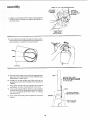
assembly
TO AVOID
BEING SCRAPED
SHOULD
BLADE
SUDDENLY UNCOIL WEAR SAFETY GOGGLES AND
CAREFULLY
UNCOIL THE BLADE HOLDING
iT AT
ARMS LENGTH.
POINTER
_--TENSION
7. Carefully uncoil the blade, holding it at arms length.
ADJ.
KNOB
8. Place the blade over the wheels with the teeth pointing
downwards
toward the table as shown. Make sure the
blade is between
the rubber tl res.
NOTE:
various
Your
widths
the blade guides
and is in the center
]
T
of
SCREW
bandsaw can be used with blades of
from 1/8" to 1/2". The saw must be
adjusted to the proper blade tension setting for the
blade to be used. A 1/4" wide blade is included with
this saw.
9. Screw down the
to 1/4. This will
blade.
tension knob
pu_ sufficient
until the pointer
points
tension on a 1/4" wide
10. Turr the upper wheel by hand a few times and notice if
the blade remains in the approx,
center of the tire on
the top wheel.
If the blade moves away from the center of the wheel
while you are turning
it, the blade is not TRACKING
properw.
The top wheel shaft is hinged which allows the wheel to
be tilted
so that the blade can be TRACKED,
By
turning the tracking adjustment
screw, the wheel will De
tilted. (see illustration).
If the blade moves toward
a.
the front
of the band saw:
Turn the tracking adjustment
screw clockwise
about
1/4 of a turn, as though you were tightening
it.
If the blade moves toward
a.
BLADE
CENTERED
ON TIRES
OF BOTH
WHEELS
the back of the band saw:
Turn
the
tracking
counterclockwise
about
were loosening it.
adjustment
screw
1/4 of a turn as though you
Turn the screw
the appro×=mate
The thrust bearings support the blade from the rear and
will rotate when the blade is pushed against them while
you are cutting.
As soon as you stop cutting,
the
bearings should stop rotating,
11
THRUST BEARING
ADJ. KNOB
THRUST
To be sure the thrust bearing is properly
supporting the
blade, turn the thrust bearing adjustment
knob so that
the bearing moves toward the blade and almost touches
it.
12. While turning
the upper wheel to the right by hand,
adjust the thrust
bearing
until
it barely
touches
the
blade and starts to rotate. Now move the bearing back
slightly,
until
it
bearing setscrew.
13. Adjust
the lower
stops
thrust
rotating.
bearing
Tighten
the
just enough to cause the blade to run in
center of the tire.
/
thrust
the same way.
14
BEARING
NOTE:
The upper and lower blade guides support
the blade
and keep it from twisting
during operation.
An adjustment
is necessary when blades are changed or replaced.
14. To adjust the upper blade guides loosen the setscrew
which locks the blade guide holder (see illustration).
APPROX.
1/32"'
BLADE GUIDE
!5. Turn
the blade guide adjustment
knob, so that the
guides move toward
the blade,
Move them until the
"ledge"
is about
1/32"
from the deepest part of the
blade teeth. This deep part is called a "gullet".
Tighten
the setscrew.
KNOB
SETSCREW
16. Adjust
the lower
guides the same way.
BLADE
v__>/
17. Press the two guides evenly
against the sides of the
blade, but don't pinch the blade. Release the guides and
rotate the upper
wheel a little bit, moving the blade
downward.
Make sure one guide is not farther
away
from the blade than the other. Tighten
both setscrews.
18. Adjust
the lower
guides
"_
GUIDE
HOLDER
SAW
BLADE
UPPER
BLADE
GUIDE
the same way.
19. Rotate the upper wheel a few times by hand, and check
the guides and thrust bearings. Make readjustments
if
necessary.
20. Replace
the blade guard
on the upper
guide support_
21. Locate the table insert and place it in the opening
table.
22. Replace
Find
THE
a
TRUSS HEAD SCREW
AND WINGNUT
the cover.
ADJUSTING
1.
1/4-20
TABLE
x
1 inch
truss
head
screw,
a regular
washer, and a 1/4-20 wing nut among loose parts.
the screw into the hole in the table top.
2.
in the
underside
of
the table,
Insert
COMBINATION
From
the
wing
tight.
nut onto the truss head screw and tighten
finger
This will keep the table flat and in alignment.
screw the washer
parts a 5/16"-18
x 3/8"
and
3.
Locate among the loose
head flat point setscrew.
4.
This setscrew acts as a 90 ° stop. Screw it partially
into
the tapped hole in the top of the table on the left side.
Use the 5/32" setscrew wrench.
5.
Raise the blade guides
6.
Loosen the
left side of
band saw.
7.
Screw in the stop screw and notice
the frame, the table will start to tilt.
8,
Place a square on the table against
the blade and
continue
to screw in the stop screw until the table is
square with the blade. Tighten "the table lock.
5/32"
SETSCREW
WRENCH
socket
all the way up.
table lock slightly
and push down on the
the table until it touches the frame of the
NOTE:
"NOTE:
SQUARE
The combination
start of "assembly"
method,"
that
as it touches
square must be "true"
-- see
section on pg. 6 for checking
9.
15
If the plastic housing should interfere
with
the underside
of the table so that4he
table
will not level, loosen the 4 boltsthat
hold the
trunnion
(see page 8) to the table and slide
the table toward the rear of the saw. Tighten
the bolts. The table should
now adjust to a
level position.
Find the pointer and a pan head thread cutting
screw
8-32 x 3/8 inches long and attach the pointer.
Set it at
0 degrees and tighten the screw.
assembJy
ON-OFF SWITCH
WARNING: DON'T CONNECT POWER COR D TO
ELECTRICAL OUTLET IN YOUR SHOP UNTIL
YOU ARE SURE THAT MOTOR ROTATION
IS
CORRECT. (SEE PAGE 5).
The On-Off Switch has a locking feature, THIS FEATURE
IS INTENDED
TO PREVENT
UNAUTHORIZED
AND
POSSIBLY
HAZARDOUS
USE
BY CHILDREN
AND
OTH E RS.
1. Insert
key into switch.
NOTE:
Rk_k
Key is made of yellow
2. To turn machine on. insert
pull end of switch out.
3.
To turn
Never
machine
leave
to a complete
band saw.
4.
the
OFF.
machine
plastic
finger
. PUSH
under
switch
lever and
lever in.
unattended
until
it has come
stop, Remove key and store remote
To lock switch
in OFF
one hand. ,. REMOVE
f
position..,
key with
hold switch
other hand.
from
IN wi_h
/
/
/
WARNING:
FOR
YOUR
OWN
SAFETY,
ALWAYS
LOCK THE SWITCH "OFF"
WHEN
MACHINE
IS NOT IN USE . . . REMOVE KEY
AND KEEP IT IN A SAFE PLACE. ,. ALSO. ,.
IN THE EVENT OF A POWER FAILURE (ALL
OF YOUR
LIGHTS GO OUT) TURN SWITCH
OFF . . . REMOVE
THE KEY. THIS WILL
PREVENT
THE MACHINE
FROM STARTING
UP AGAIN WHEN THE POWER COMES BACK
ON.
4OLD
/
I
16
/
/
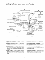
geffing to know
your band saw/sander
2
/--TENS,ON
A UST,
NG
K.OB-COVER.ETAINING
CL,P"\
8
GUIDE
BAR LOCK
SCREW
3
TENSION
(Inside)
SCALE
CORD
OUTLET
"7
THRUST
BEARING
ADJ. KNOB
(Lower Knob
Not Shown)
TI LT LOCK
HANDLE
\
SAW PULLEY
BLADEGUIDE
ADJ. KNOB
(Lower
Knob Not Shown)
BA CK
FRONT
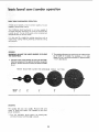
1. ADJUSTMENT
DIAGRAMS . . . Help you to become
familiar with the adjustments,
5.
2. TENSION
ADJUSTMENT
KNOB
. . . Tightening
the
knob will increase the tension on the blade. Loosening
it will decrease the tension.
3. TENSION
SCALES...
The fractional
the correct blade tension for various
6.
BLADE
GUIDE
moves
the guides
LATERAL
ADJUSTMENT
BLADE
GUIDE
guides can be adjusted
by the setscrews.
markings indicate
widths of blades.
7.
For example, when installing a 1/4" wide blade, tighten
the tension knob until the pointer is pointing to the 1/4
BLADE
THRUST
ing the knob
various widths
. - . Turning
in or out for various
ADJUSTMENT
sideways
BEARING
moves the
of blades.
widths
....
and locked
ADJUSTMENT
thrust
bearings
the knob
of blades.
The
in position
. . . Turnin or out
for
marking.
4.
TABLE
TILTING
. . . Loosen the table lock handle, tilt
the table to the desired angle and tighten the lock handle.
To return the table to the 90 ° position, tilt it until the
90 ° stop screw rests on the frame, then tighten
handle.
8.
GUIDE
BAR
LOCK
SCREW...
The upper
blade guides
should just clear the workpiece
while cutting.
Always
adjust the guides before turning
on the band saw and
lock the guide bar by tightening
the thumb screw.
the lock
17
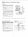
getting to know your band saw/sander
9. GUIDE
BAR
When the upper guides are raised or lowered, they must
not deflect the blade sideways. This means th at the guide
bar must be parallel to the blade, or square with the
table.
SCREW
1. Remove the blade guard, cover, blade, and the upper
guide assembly.
2.
Lower
1-3/4"
the guide bar until
from the table.
3.
Hold
4.
If the bar s not square with the table, lock the guide
bar and oosen the four screws in the guide bar
support
witl_ a 3/16"
setscrew wrench
To reach the
a square
lower
wheel
on
left screw,
ouTwara.
the
the end
table
it wil
=s approximately
against
be necessary
the
guide
to tilt
6. Be sure to
INSTALLING
replace
SANDING
_//3/16'"
bar
SETSCREW
WRENCH
BAR
COMBINATION
SQUARE
the upper
NOTE:
'The holes in the guide bar support
than the screws. This allows the support
to
5. Move the guide bar until
then tighten the screws.
(4 Total}
/
are larger
be moved.
it is square with
the table,
the blade guard before
operation.
ATTACHMENT
,/
/'
WARNING:
FOR YOUR OWN SAFETY, TURN SWITCH
"OFF" AND ALWAYS REMOVE PLUG FROM POWER
SOURCE OUTLET BEFORE INSTALLING
SANDING
ATTACHMENT.
1. Remove
the blade guard,
alignment
screw.
2. Remove the cover
the blade.
the table
release the blade tension
5.
and
the table
and remove
HEX. HD. SCREW
assembly.
Use a 7/16"
Loosen the setscrew that locks the lower thrust bearing,
ano move the bearing as far back as it will go. Retighten
setscrew
Loosen
the
two
K(O/)I
.UPPER
BLADE
GUIDE
ASSEMBLY
3, Remove
the upper blade guide
wrench to remove the screw.
4.
insert,
setscrews
that
lock the
lower
blade
guides. Spread them apart so that the end of each guide
is inside the holder. Retighten
setscrew.
18
6, Attach
the sanding platen to the guide bar with
the
same screw that held the upper blade guide assembly.
Do not tighten the screw at this time.
On the smooth side of the sanding belt, you will find a
"directional
arrow".
The belt must run in the direction
of
this
arrow
so that
the
splice
does not
7. Place the belt on the wheels and
knob until
the pointer
points
to
upper wheel by hand a few times to
belt is tracking
properly
and is not
come
apart,
3
tighten
the tension
SAND.
Rotate
the
make sure that the
rubbing the guides.
8, Loosen the guide bar lock screw and
the sanding
platen below the table.
lower
the end
PLATEN
of
¢
SANDING
ICENTER
OF SLOT
I
9. Locate among the
flat head machine
and Iockwasher.
loose parts, the alignment
plate,
a
screw 6-32 x 7/16",
a small hex nut
TABLE
_0, Attach
the alignment
plate to the insert so that the end
of the alignment
plate is in the center of the slot in the
insert.
Place
the
insert
in the
opening
in the
/
table.
iNSERT
SCREW
_
i
[
/
__[:::::::_
LOCKWASHER
_.N
PLATEN
;ANDING
BELT
U T _...//A
PLATE
LI G N M E NT
SANDING
BE LT
AND PLATEN
11.
Hotd a square on the table against
platen.
12. Tighten
the hex.
the guide bar.
13.
Replace
head
screw which
the sandinc3 belt
holds
the platen
and
COMBINATION
to
the cover.
WARNING:
FOR YOUR
OWN SAFETY,
DO NOT SAND
IRON
OR STEEL BECAUSE
THE SPARKS
COULD
IGNITE
THE
SAWDUST
INSIDE
YOUR
BAND
SAW.
19
SQUARE
basic band saw/sander
BASIC BAND SAW/SANDER
operation
OPERATION
A band saw is basically a "curve
capable of doing inside cutting.
cutting"
machine.
It is no_
Your Craftsman
Band Saw/Sander
is no_ only capable of
the usual band saw operations,
out it can he converted
into
a sander as well. You can finish wood, certain compositions
and plastics and non-ferrous
metals.
It is also used for stra ght-line
crosscutting,
ripping, mitering,
and resawing.
cutting
beveling,
operations
compound
such as
cutting,
SAWING
WARNING: ADJUST
THE WORKPIECE.
THE UPPER GUIDES
TO CLEAR
2. The smallest
1. Use both hands while feeding the work into the blade.
Hold the workpiece
firmly against the table. Use gentle
pressure,
and do not force the work, but allow the blade
to cut.
BLADE
BLADE
StZE
1"
SELECTION
GUIDE
FOR
MINIMUM
CIRCLE
3"
I"
3"
16
4
8
SANDING
The sanding
belt cuts very
scraps of wood
first
before
actual workpiece.
rapidly.
Practice
with
some
you attempt
to sand your
1. Press the workpiece
gently
against
the sanding
and keep moving it until the edge is smooth.
diameter
that can be cut out is determined
by the width
of the blade.
blade will cut a minimum
1-1/2".
CSee Chart)
belt,
20
For example,
a 1/4"
wide
diameter
of approximately
CUTTING
1"
maimtenamce
WARNING:
FOR YOUR OWN SAFETY, TURN SWITCH
"OFF"
AND REMOVE PLUG FROM POWER SOURCE
OUTLET BEFORE
MAINTAINING
OR LUBRICATING
YOUR BAND SAW,
GENERAL
ON-OFF
SWITCH
t__o o_3.
MAINTENANCE
Pitch and sawdust
that accumulate
on the tires should be
removed with a stiff brush or scraped off with a piece of wood.
Do not use a sharp knife or any kind of solvent.
POWER CORD
A
E
GREE
Do not allow pitch to accumulate
on the table, the insert, the
guides or the thrust
bearings.
Clean them with
Craftsman
Gum and Pitch Remover.
CAUTION:
Do not immerse
the
thrust bearings.
Apply a thin coat of automobile-type
the wood slides easily while cutting.
wax on the table
MOTOR
MAaNTENANCE
LUBRtCATRON
AND
GROUND
WIRING
I. The bearings, }n both end shieJds of the motor, have been
lubricated at the factory with correct lubricant.No other
requires lubrication.
2. Re-lubricate motor bearings in accordance
with the
instructions on the nameplate. Be sure to wipe off dirtor
gritifpresent around oilhole caps toprevent any possibility
of foreign material contaminating the oilwicks that supply
the bearings with oil.Use a good grade of medium weight
mineral oil,such as automobile engine oil,SAE 20.
3. If disassembly of the motor is necessary, it should be
returned
to your nearest Sears retail or mail-order
store in
order to prevent
voiding the guarantee.
RECOMMENDED
4.
of this
Cat,
...................................
No.
9-22213
9-22236
9-2222!
9-22222,
Miter Gauge
..................................
Hold-Down
Clamp for Miter Gauge
.............
Stop-Rods
for Miter Gauge
.....................
Rip Fence .....................................
Blades and Sanding
Belts ...................
Circle Cutting Attachment
......................
Table Extension
...............................
Speed Reducer
................................
Power Tool Know How Handbooks
Radial Saw
....................................
Table Saw
.....................................
9-29929
9-29928
9-29924
9-23433
See Catalog
9-24301
9-24302
9-23896
The above recommended
accessories
are current
available at the time this manual was printed.
21
cannot
be reg,;fated
o
NOTE: Motors used on wood-working
tools are particularl
susceptible
to the accumulation
of sawdust and wood chip
and should
be blown
out or "vacuumed'"
frequently
t,
prevent
interference
with
normal
motor ventilation
an,
proper
operation
of the centrifugally-operated
startin,
switch.
ACCESSORIES
Steel Leg Set
.................................
Caster Set ..........................
motor
Every effort should be made to prevent
foreign
materia
from entering
the motor When operated under condition
likely to permit accumulations
of dust, dirt, or waste withll
the motor, a visual inspection
ehou#d be made at frequef_
intervals.
Accumulations
of dry dust can usually be b_ow_
out successfully.
8tern
Stand
GROUND
DIAGRA,"_
so that
NOTE:
The speed
changed.
Floor
_ MOTOR
_ET
i
When the tires become worn they should be replaced. When
replacing
the tires, stretch
them around the wheels butdo not
glue them onto the wheels.
part of the motor
--
_J uG,r
9.2917
9-2918
and were
trouble shooting
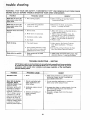
WARNING:
FOR YOUR OWN SAFETY, TURN SWITCH "OFF" AND REMOVE
SOURCE OUTLET BEFORE TROUBLE SHOOTING YOUR BAhiD SAW/SANDER.
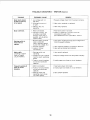
TROUBLE
PROBABLE
Blade does not run in the
approximate center of the
Blade
does not run in the
approximate
center of the
lower wheel,
Band Saw slows down when
cutting.
1. Not
tracking
1. Lower
CAUSE
properly.
wheel not
correctly
on
pivots
3, Cutting
too
4. Dull
REMEDY
1. Adjust
tracking,
see Assembly
"Installing
the Blade."
positioned
1. Rep0siLion
shaft.
Section,
1. Belt too loose.
2. Motor
PLUG FROM POWER
1. Adjust
in motor
base.
small a radius.
belt
see Assembly
the Blade."
tension,
see Assembly
Section,
"Attaching
Belt Guards."
2, Tighten
motor base clamp screws. See
Assembly Section,
"Motor
Installation".
3. Stop feeding, and back up the material
slightly,
4. Replace
blade.
the wheel,
"1 nstalling
Section,
until the band saw speeds up.
blade.
i,
Blades breaking,
Blade dulls too
1, Too much tension.
quickly.
1. Adjust
tension. See Getting To Know
Your Band Saw/Sander,
"3 Tension
Scales."
2. Kink in blade caused by cutting
too small a radius or turning the
material too fast when cutting.
2, Use correct
cutting technique.
See Basic
Band Saw/Sander
Operation
Section.
1. Blade guides
1, Adjust
set too close
to teeth.
upper
Assembly
TROUBLE
SHOOTING
and
Section
lower blade guides.
"installing
See
the Blade."
-- MOTOR
MOTE: Motors used on wood-working
tools are particularly
susceptible
to the accumulation
of sawdust and wood chips and should be blown out or "vacuumed"
frequently
to prevent
interference
with normal
motor ventilation
and proper
operation
of the centrifugallyoperated starting switch.
TROUBLE
Excessive
noise.
Motor fails to develop
full power. NOTE:
LOW VOLTAGE:
[Power
output
of motor
decreases
rapidly with
decrease
in voltage at
motor terminals.
For
example,
a reduction
of
10% in voltage
causes
a reduchon
of 19% in
maximum
of which
PROBABLE CAUSE
REMEDY
1. Motor.
1. Circuit
lights,
other
Have motor checked
oy qualified
service
technician.
Repa=r service is available
at
your nearest
Sears store.
overloaded
with
appliances
motors.
2, Undersize
wires
1. Do not use other appliances
same mrcuit when using the
and
or circu=t
on
2, Increase wire sizes, or reduce
length
of wiring.
See "Motor
Specifications
and Electrical
Requirements"
section.
too long.
3. General
overloading
power company
facilities.
or motors
saw.
of
3. Request
a voltage
corn ;)any.
power output
the motor is
capable,
and a reduction
of 20% in voltage causes
a reduction
of 36% in
maximum
power output.)
22
check
from
the
power
TROUBLE
TROUBLE
Motor starts siow{y
or faiJs to come up
to full speed.
SHOOT_NG
PROBABLE
t. Low voltage
trip relay.
2. Windings
or open.
1. Motor
will
REMEDY
not
burned
1. Request
out
not
cooling.
{Air
restricted
1. Burned
switch
contacts
1, Starting
switch
operating.
repaired
3. Have relay
replaced.
1. Feed
slower
work
from
the power
company.
or replaced.
into
blade.
to provide
normal
air
motor,
and Lubrication"
section
1. Have switch replaced and request a voltage check
from the power company,
(due to extended
hold-in
periods
caused
by tow line voltage,
etc.)
2. Shorted
capacitor
3, Loose or broken
connections.
Motor stalls
(resulting in blown
fuses or tripped
circuit breakers).
check
2. Clean out sawdust
circulation
through
See "Maintenance
through
motor due to
sawdust,
accumulating
inside of saw).
Starting switch in
motor will not
operate.
voltage
2, Have motor
overloaded.
2. Improper
circulation
(Cont.)
CAUSE
3. Starting
relay
operating.
Motor overheats.
-- MOTOR
not
2. Voltage
too low to permit
motor to reach operating
speed.
3. Fuses or circuit
breakers
do not have sufficient
2. Have
capacitor
3. Have
wiring
checked
1. Have
switch
replaced.
2. Request
3. Install
tested
voltage
proper
and
and
check
size fuses
replace
if defective,
repaired,
from
the power
or circuit
company.
breakers.
capacity.
Frequent opening of
fuses or circuit
breakers.
1. Motor
overloaded.
1. Feed
work
2. Fuses or circuit
breakers
do not have sufficient
capacity.
2. Install
3. Starting
switch
not
operating
(motor
does
not reach speed).
3. Have switch
23
slower
proper
into blade.
size fuses
replaced.
or circuit
breakers.
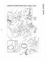
CRAFTSMAN
12-INCH
BAND
SAW/SANDER,
MODEL
113.243300
& 113.243311
"tO
Q
_o
,/
/
SEE FIGURE
FOR
EXPLODED
VIEW
32
14
f
\
/
46
m
45 _.I._
®
2
31
3
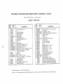
CRAFTSMAN
12-iNCH
BAND
SAW/SANDER,
Always
order by Part Number
FIGURE
PART
NO.
IKEY
NO.
69069
41815
38524
37158
41711
STD315228
69028
41812
10
11
12
13
14
15
16
17
18
19
20
21
22
23
Frame
with
Trim
Screw, Self-Locking
Ring, Retaining
5/8
Washer,
Spring
Bearing,
Ball
Wheel,
Upper Drive
Ring, Internal
Retaining
1-3/8
Key, Switch
Clip
*Bearing,
Ball
Ring, Interna! Retaining
1-11/16
*Screw,
Type "'T" 10-32 x 1/2
*Key, Square 3/16
x 1-1/4
*Screw,
Set, 5/16-18
x 1/2, Soc. Hd., Cup Pt.
tPulley,
1/2 V Groove, 5" x 5/8 Bore,
Keyed with Set Screw
Clip, "S '"
Guard, Belt
tBelt,
"V" Type, 1/2 x 52
fPulley,
1/2 V Groove, 2-1/2"
x 5/8 Bore,
Keyed with Set Screw
60256
69085
STD315238
38884
STD601105
STD580104
STD503105
STD328052
60255
60252
STD204520
STD328022
69184
60254
69183
60253
Bracket,
Mounting
Bracket, Support
Motor (Model
113.243311
Support,
Belt Guard
*Standard
?Stock
DESCRIPTION
Cover,
Tire
Hardware
Item -
Item -- May be secured
through
113.243300
& 113.243311
-- not by Key Number
1 PARTS
LiST
KEY
NO.
PART
NO.
25
26
27
28
29
30
31
32
33
34
35
36
37
38
39
40
41
42
43
44
45
46
i453068
i69084
;STD541031
STD522503
69023
65013
69004
STD601103
i69078
_69059
69058
69025
60272
_37887
_60096
37911
69062
133427
169005
STD551106
STD541006
69037
69185
69139
69140
69141
Only)
May Be Purchased
MODEL
DESCRiPTiON
*Screw,
5/16-18
x 3/4, Sems, Hex, Hd.
Foot, Frame
*Nut, Square, 5/16-18
*Screw,
Truss Hd., Slotted
1/4-20
x 3/8
Spacer, Bearing
Elbow
Clamp, Tube
*Screw,
Pan Hd. 10-32 x 3/8
Gasket, Foam
Wheel,
Lower Drive
Shaft, Lower Wheel
Lens
tBlade,
Band Saw, 1/4 x 80
tWrench,
Hex., "L", 1/8
fWrench,
Hex., "L', 5/32
tWreneh,
Hex, "L", 3/16
Platen, Sanding
*Screw,
Flat Hd., 6-32 x 7/16
Plate, Sanding Alignment
*Lockwasher,
No. 6
*Nut, Hex., 6-32
tBelt, Sanding,
1/2 x 80
Owner's
Manual
(Not Illustrated)
Bag Asm.
Bag Asm.
Bag Asm.
Loose
Loose
Loose
Parts
Parts
Parts
(Not Illustrated)
(Not Illustrated)
(Not Illustrated)
Locally.
the Hardware
Department
of most Sears or Simpsons-Sears
Retail
Sto_es or Catalog
Order
Houses.
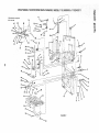
CRAFTSMAN
12-INCH
BAND
SAW/SANDER,
MODEL
113.243300
& 113.243311
Q
FOR WIRING DIAGRAM
SEE PAGE 26
67
me
=0
Q
68
\
I
I
[
9
10
2o
44\
O'
I
12
13
14
I
18
7i \
16
12
17
FIGURE 2
"_"'"_
2o
6
CRAFTSMAN
12-INCH
BAND
SAW/SANDER,
FIGURE
PART
NO.
KE_
NO
1
2
3
4
5
6
7
STD522503
60386
63266
69031
30613
STD600803
60321
8
STD502502
9
69042
10 69099
69100
69021
STD541037
69077
69072
STD551037
i38724
i69070
iSTD551!31
!9416187
!69029
ISTD572507
69068
41426
69022
69019
69089
!STD533725
i69057
ISTD541625
ISTD651025
i60323
69094
69063
69024
60190
*Standard
tStock
Hardware
Item
DESCR
Wheel
*Bolt, Carriage,
Trunnion
Tension
3/8-16
x 2-1/2
_Nut, Wing 1/4-20
*Washer,
9/32
x 5/8 x 1/16
Screw, Truss Hd., !/4-20
x 1
Table
Insert, Table
Pin, Lower Guide Support
Screw, Self-Locking,
5/16-18
x 3,/8
Item
-- May Be Purchased
-_ May be secured
through
2 PARTS
113.243300
& 113.243311
LiST
KEY
NO.
IPTION
*Screw,
Hex Hd., Type "'T', 1/4-20
x 3/8
Washer,
Plain, 15/32
x 1-3/8
x 3/64
Bushing
Knob Assy., Tension Adjustment
Clamp, Cord
*Screw,
Pan Hd, Type "'T'" 8-32 x 3/8
Screw, Thumb 5/16-18
x 1-1/2
*Screw,
Set, 1/4-20
x 1/4 Sec. Hd., FI. Pt.
Sleeve, Thrust Bearing
Knob Assy., Thrust Adjustment
Knob Assy., Guide Adjustment
Pin, Trunnion
*Nut, Hex. 3/8-16
Spacer
Wrench
*Washer,
Plain, 3/8 x 1-1/8
x 7/64
Pointer, Tilt
Frame Assy., (Incl. Key Nos. 12 & 35)
*Lockwasher,
Ext. 5/16
*Screw,
Hex, Hd., 5/16-18
x 3/4
Bumper,
Upper Wheel
*Pin, Roll 1/4 x 3/4
Guide Assy., Fulcrum
(Includes
Key No. 22)
Bracket, Upper Wheel
Support
Rod, Upper Wheel Guide
Spring,
Pointer
MODEL
37
38
39
40
41
42
43
44
45
46
47
48
49
50
51
52
53
54
55
56
57
68
59
60
61
62
63
64
65
66
67
68
69
70
71
72
73
74
PART
NO.
69039
69045
STD561031
STD581031
STD502503
STD502505
STD512505
STD315505
69038
STD522508
STD551125
69041
STD601103
69044
69043
69035
216278
69036
69034
62295
30682
STD551225
STD522512
STD372252
69014
STD551208
STD510802
69009
STD600603
STD661206
447845
69010
60257
69082
69026
STD375006
69027
67073
DESCRIPTION
Guide, Blade
Guide, Lower Blade
*Washer,
5/16 x 9/16
*Ring, Retaining,
5/16
*Screw,
Soc. Hd. Cone
*Screw,
Set, 1/4-20
x
*Screw,
Mach., 1/4-20
*Bearing,
Ball
Guide, Upper Blade
*Screw,
Mach., 1/4-20
*Lockwasher,
1/4
Support,
Upper Blade
*Screw,
Pan Hd., Type
Guard
Knob, Upper Guide
Bar, Guide
x 1/16
Pt. 1/4-20
x 1/4
3/4, Soc. Hd., FI. Pt.
x t/2,
Pan Hd.
x 7/8,
"'T'" 10-32
Department
of most Sears or Simpsons-Sears
Retai{
x 5/16
*Screw,
Soc. Hd. Cap, 1/4-20
× 1/2
Support,
Guide Bar
Spring,
Guide Bar
Spacer
*Nut, Speed
* Lockwasher,
External Tooth 1/4
*Screw,
Pan Hd., 1/4-20
x lq/4
*Bulb, Light 116/1 26V, 25 Watt, Db!.
Socket,
Light
*Lockwasher,
No. 8
*Screw,
Pan Hd., 8-32 x 1/4
Relief Strain
*Screw,
Pan Hd. 5-32 x 3/8
*Lockwasher,
Int. 6
Screw,
Pan Hd. Type "T",
Box Assy., Switch
Switch,
Locking
Gasket, Switch Box
Cord Assembly
*Connector,
Wire, 14-18
Outlet
Relief,
1/4-20
Assembly
Strain
Locally.
the Hardware
Hex. Hd.
Stores or Catalog
Order
Houses.
x 3/8
CRAFTSMAN
12-tNCH
BAND
SAW/SANDER,
3 ---'--e
MODEL
el'_'--"
113.243300
/,-'7
4
/'/7
SUPPUED
Key
, No,
1
2
3
4
5
6
7
8
9
10
FIGURE
MODEL
WiTH
Part
3
113.243311
No,
Description
62614
Leg
t'Screw,
60314
STD541025
Truss Hd,
f'Nut,
Hex 1/420
t*Lockwasher,
1/4
STD551225
68060
Channel,
Stiffener,
68059
62615
68061
STD541050
803835
Stiffener,
End
Support,
Motor
Hex Hd
f
Leveling
Foot,
'Bag
FOR
1/4-20
External
1/2-13
of Loose Parts
MOUNTING
TOOL
& MOTOR
STD523110
t'Screw,
STD551131
t*Lockwasher,
STD541231
STD551031
f'Nut,
Hex Jam 5!16-18
t'Washer,
11i32x11/16xl/16
STD532507
t'Bolt,
Hex Hd. 5/1 6-18
Hardware
Item
All
Conta=ned
In Loose
-
x 1
Ext. 5/16
Carriage
Standard
Parts
x 5/8
Support
Side
f_Nut,
69097
HARDWARE
ONLY
5/16-18
x 3/4
May Be Purchased
2$
Parts
Bag
Locally
& 113.243311
CRAFTSMAN
12-iNCH
BAND
SAW/SANDER,
MODEL
113.243300
& 113.243311
NOTE:
ANY ATTEMPT TO REPAIR THIS MOTOR
MAY CREATE A HAZARD UNLESS
REPAIR IS DONE BY QUALIFIED
SERVICE TECHNICIAN.
3
REPAIR SERVICE IS AVAILABLE
AT YOUR NEAREST SEARS STORE.
\
\
\
@-
FIGURE
SUPPLIED
Key
No.
4-MOTOR
PART NO. 69183
WiTH
MODEL
113.243311
ONLY
Part
No.
60306
Description
Screw,
8-32
x 3/8,
Cutting,
Slotted,
Hd.
Cover, Terminal
64088
64258
Cord with
Thread
Serrated
Plug
TERMINAL
MOTOR
GREEN
CONNECTIONS
WARNING:
FOR
YOUR
OWN
SAFETY,
NEVER
CONNECT
PLUG TO POWER SOURCE
OUTLET UNTIL
ALL ASSEMBLY
STEPS ARE COMPLETED.
iNTERNAL'
LOCKWASHER
1. Open motor connector
box cover located on left end of
motor (viewed
from rear of saw) using a flat blade
screwdriver.
2. Remove
GREEN
SCREW
and
Iockwasher
and
insert
screw through
round metal terminal
on the end of the
GREEN wire of power cord with tockwasher
between
terminal
and motor frame. (See illus.)
3. Reinsert
securely.
GREEN
SCREW
in the threaded
hole.
Tighten
-TO
4. Insert terminal
marked
T4 on
seated.
end of WHITE wire on spade terminal
the motor.
Push terminal
firmly
until
5. Insert terminal
marked
T1 on
seated.
end of BLACK wire on spade terminal
the motor.
Push terminal
firmly
until
GREEN
GREEN
WIRE
SCREW
STRAIN RELIEF
pOVE
TERMINAL
6. Close motor connector
box being sure that power cord is
seated in the largest strain relief groove, and tighten box
cover screws.
29
TO
T4
NOTE5
30
NOTES
31
SERVICE
Now
that
you
Saw!Sander
parts
should
or service,
Center
MODEL NO.
113.24330(}
have purchased
and
a need
simply
most
your
ever
contact
Sears,
12-Inch
exist
Band
for
repair
any Sears Service
Roebuck
Be sure to
call or visit.
provide
all
pertinent
The
number
of
your
and
Co.
stores.
facts
when
you
SAW ONLY
MODEL NO.
113.243311
model
Sander
will
be found
hand side of the saw.
SAW WITH LEGS
AND MOTOR
WHEN
HOW TO ORDER
REPAIR PARTS
ORDERING
GIVE
THE
PART
NUMBER
on
parts
Service
FOLLOWING
you
will
Parts
Sol(i
by
Part No. 69185
SEARS,
ROEBUCK
need
may
and
are
be electronically
Distribution
AND
CO.,
Form No. SP4922_2
Saw/
the
right-
at
ALWAYS
INFORMATION'
DESCRIPTION
NAME
OF ITEM
12-Inch
Band
be
most
not
Band
PARTS,
PART
listed
Center
a plate
REPAIR
MODEL NUMBER
113.243300
113.243311
All
12-Inch
ordered
Sears
stocked
from
stores.
locally,
transmitted
Center
Chicago,
for
Saw/Sander
any
If the
Sears
parts
your
order
to a Sears
Repair
handling.
IL.
60684
Printed
U.S.A.
in U.S.A.
6/87