1
JAGUAR
SERVICE BULLETIN
Number
Section
Sheet
Date
J .1
Front Suspension
1 (of 1 )
Janua.xy, 1960
TOP WISH:BCNE BALL JO:mT LUERICATION
Mark 2 Models
If di.fficulty is experienced in greasing the top wishbone ball
joints on early cars fitted with a right-angled nipple replace the
nipple with a straight type Part mnnber c. 30W1 as fitted to the lower
wishbone ball joint.
Jaguar Cars Limited 2005
March, 1960
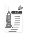
smVICE BULLETIN NO. J. 2
The
~bove
numbered Service Bulletin is not for general cir-
allation and the Distributors and Dealers whom it ooncerns have al-
ready been issued with their copy.
If you are not in possession of' a copy of' Service Bulletin
No. J.2 insert this sheet in your folder in its
~lace.
,_.
Jaguar Cars Limited 2005
JAGUAR
SERVICE BULLETIN
Number
Section
J.2
Front Suspension
1 (of 3)
Sheet
Date
January. 1 960
YODIFICATIOO TO FRC!fr SUSPmSIOO
2.;;, 3.4 and 3. 8 litre Mark 2 Kodela
All cars of the above types prior to the following cllasais
IU.Dnbers are to be oalled in with all possible speed for in3peotion
and modification as follo1f'B:-
R.H. Drive
L.H. Drive
100676
150540
125250
200279
211029
2.4-litre Mark 2
3. 4 litre Mark 2
3.8 litre Mark 2
175278
(A)
Jack up under the front suspension aross member and. reiOOve the
two front road -wheels.
If the rebound atop pla te can be s een projecting from the side
of the :t'ront upper wishbone l ever When the suspension is in the full
rebound position (as iniicated by the arrow in Fig.1.) the following
Jmdifioation must be carried out.
Parts required:.Addi tionaJ. rebound stop plate
"
"
~
"
XL.3292
XL. 3293
Right-hAM
Left-hand
(B)
On all oars prior to the dlassis nunibers quoted above and whether
or not the reboUDi stop plates were fitted correctly in origi:cal.
production the upper wishbone levers are to be changed for the
mOdified t,ype. (see Fig.3~)
No. off
Kodified type
C.16798
c.16799
Wishbone lever
Wishbone lever
2
2
Continued
Jaguar Cars Limited 2005
Modification Procedure
(1)
Place a support under the coil spring pan at each side and lower
jack sli8Ptly so that weight of suspension is taken.
(2)
Remove the two bolts securing the upper wishbone levera to the
upper ball joints.
Take care to keep the ahima and packing pieoe
in their correct relative positions or the castor angle will be
upset.
Note:
(.;)
Support the weight of' the brake disc or hub so that
the flexible brake hose is not allowed to become
extended when the wishbone levers are disconnected..
Disconnect the f'ront m::>untings of the front suspension crossmember assembly by removing the four bolts; slacken the bolt
securing each rear mounting to the chassis side member.
This
will a.f'f'ord the necessary clearance to allow the rear Wishbone
levers to be removed when the front end of the suspension un:lt
is lowered.
(4) Remove the m1t and bolt which secures the upper wishbone levers
together.
Withdraw the split pins and unscrew the two s lotted nu.ts.
Rellk)ve the washers and wishbone levers not ing that the inner
washers are c:hamfered arown the hole and that the chamfer mu.st
be fitted inwards.
(5) Out or :file a piece out of' the reb:nm:l stop plate as shown in Fig. 2.
(6)
Weld the additional. rebound stop plates on top of' the existing
plate in the position shown in Fig.2. that is, at the top, bottom
and front edges of the plates.
The plates are handed and the
widest end of the plate must be f'i tted at the rear.
Note:
The necessary welding !!1!1 be carried out with arc
welding (not gas) equipment and the bra.lce disc, coil
spring and brake flexible hose sui tabl.y protected
with asbestos sheeting or similar material f'rom
welding "f'lashes".
Before carrying out a:rzy welding dleck that the new
plate seats down on the existing plate otherwise
remve the surplus weld at the point where existing
plate is welded to f'ront suspension cross member.
Contimed
Jaguar Cars Limited 2005
Sen:ice Bulletin no.
J. 2
continued
Sheet
2 (of 3)
(7) Reassemble the modified wishbone levers
and :tUlly tighten the
slotted nuts with the wishbone levers positioned as near as
possible to the no:nnal riding position, that is, approximately
horizontal.
(8)
A:f'ter oompleting re-assembly, it will be necessary to check and
reset if necesaar.y, the castor, camber and f'rcnt wheel alignment.
The procedure f'or adjusting the castor and camber angles is
described on pages J .1 8 and J .19 ot the Front Suspension section ot
the Mark 1 2.l,/3.4 litre Service Manus] but the settings are as
follows:Camber Angle
2.4, 3.4
and
3. 8 litre Mark 2 Models
Castor Angle
! 0 :t i 0
0° :
*
0
It will be noted that there are two alternative operations.
Operation 1.
Check position of rebound stop plates.
I f inoorrect,
modifY rebound stop plates and fit JOOdified wishbone
levers for whidl the l abour allowance time will be 6i
man hours.
Operation 2.
Inspect rebound stop plates for oorrect position on
front suspension cross member.
It correct, fit modified
wishbone levers for \vhich the labour allowance time is
man hours.
st
It is the responaibility of each distributor to ensure that all
cars sold by them direct or through their dealers or to the motor trade
in their territory or held in stock in their territory are oal.led. in
for inspection and modification with all possible speed.
We do not desire this zoodif'ioa.tion to be carried out other than
by Jaguar Distributors and Dealers and cars originally supplied. through
or stocked by non-oontracting traders DllSt be called in and modi:t"ied by
the distributor or dealer who supplied the car to the tre.der.
The necessary supply of parts to cover the estimated requirements
of each distributor is being f'orwarded. by the Jaguar Spares Department to
the distril:utors concerned.
Continued
Jaguar Cars Limited 2005
Distributors and. dealers are to notit'y the Service Department,
Jaguar Cars Limited, of fm3' cars they have sold to customers not
residing in their territory which by virtue of distance they cannot
conveniently inspect ani ~n>dify and for which cars Jaf!}lllr Cars Limited,
will aJ:Tange for action to be taken by the nearest Jaguar dealer.
Individual guarantee claims for material and labour are to be
su.bnitted in the nonm~.l aa.nner, the labour section being endorsed
"Modification per Service Bulletin J.2" - Operation 1 or Operation 2
as the case may be.
For Export countries displaced wishbone levers are to be
returned to the Distributor who will be responsible for en:ruri.ng that
they are scrapped preferably by cutting the levere into two pieces.
For the Home market, displaced wishbone levers are to be
returned via the Distribt1tor to Jaguar Cars Limited., Coventry.
Jaguar Cars Limited 2005
Service Bulletin no.
J. 2
continued
FRONT
Sheet
3 (of 3)
-4-c:-
/
Widest end of
plate to rear
Jaguar Cars Limited 2005
ORIGINAL
TYPE
0
MODIFIED TYPE
Jaguar Cars Limited 2005
JAGUAR
·SERVICE BULLETIN
Number
Section
J.3
Front Suspension
1 (of 1)
Sheet
Date
March, 1960
KODIFICATICfi TO FRONT SUSPENSION COU. SPRINGS
(Ma,rk 2 Models)
Models a.f't'eoted.
Commencing Chassis Numbers
R.H. Drive
100731
150562
200301
2.4 litre Mark 2
3.4 litre Mark 2
3. 8 litre Mark 2
L.H. Drive
125269
175292
21104-1
On cars with the above chassis numbers and onwards the front
suspension coil springs are increased in length by !•• (3.2 IIIIl) and an
extra. i" (3.2 mm) packing piece fitted at the top of' the ooil spring
f rom the cxmmencem.ent of' production is no longer used.
Cars are f'i tted with coil spri,ngs and packing pieces in accorda nce with the following details.
Cars up to above
chassis numbers
2.4- litre
Coil Spring - part no.
0892lt/1
Thickness of Packing
P:!,eoes
- colour code of spring
White
Blue
Green
t:
Red
Yellow
Purple
(~"
= 3· 2
3.4- litre
3. 8 litre
C12585
Cars on and a:f'ter
above chas sis numbers
2.4 l i tre
i" =6.4 mm
C16954
C16953
t"
lf"
Not fitted
t:
Not fitted
Jilin
3.4- litre
3. 8 litre
1
It
l·
Not fitted
f" =9. 5 IIm)
/Cont'd•••
Jaguar Cars Limited 2005
-
-- -
-
- - --
InterChangeabilitx
The latest type springs are interchangeable with the earlier
type provided the packing pieces are fitted. in accordance with the
above details.
Note:
The oolour code of' the spring is represented by a small patch of
paint on the centre coils.
Jaguar Cars Limited 2005
JAGUAR
SERVICE
BULLETIN
Number
Section
J.4
Sheet
Date
Front Suspension
1 ( of 1)
May, 1960
STIFFER SETTING FRONT DAMPERS
(Mark 2 Models)
Models affected
'
CoDmencing Chassis Numbers
2.4 litre Mark 2
3.4 litre Mark 2
3.8 litre Mark 2
R. H. Drive
L. H. Drive
101847
151204
200853
1254.66
175581
212293
On oe.rs with the above chass is m.unbers and onwards front hydraulic dampers with sti:N'er settings (Part :number 0.14.935) are fitted.
This type of damper has the number NF. 640.54137 stamped on the
bo~.
Interchangeability
The above dampers are interchangeable with the previous type
fitted provided they are rep laced in pairs.
Spares Bulletin No.
J.7
refers.
Jaguar Cars Limited 2005
jAGUAR
SERVICE BULLETIN
Number J. 5
Section Front Sus pens ion
Sheet 1 (of l)
Date February, 1961
FORGED UPPER WISHBONE LEVERS
(Kark 2 Yodels)
Models Affected
2.4
2.4
3.4
3.4
3.8
litre
litre
litre
litre
litre
3.8 litre
with
with
with
with
with
with
disc
wire
disc
wire
disc
wire
Commencing Chassis Numbers
R.H. Drive
L . H. Drive
wheels
wheels
wheels
wheels
wheels
wheels
104864
104946
152964
152983
202372
202401
125898
125903
176309
176314
215151
215155
On c ars with the above c h assi s number s and onwards forged
u pper wishbone levers replace the pressed s t eel type.
If repla.cement of the upper wishbones is necessary, for example
a fter accidental damage, the fo rged type levers can be used to replace
t he pressed steel type, in car se ts , provided the following parts are
u sed.
Part Number
No . off I!er car
C.l7176
Upper wishbone lever
2
C.l7177
Upper wishbone lever
2
C.l7171
Long bolt for ball joint
2
c .17172
Rebound stop rubberR
2
C.l7170
Stop bolt
4
.FG.l06/X
Spring Washer
4
Jaguar Cars Limited 2005
JAGUAR
SERVICE BULLETIN
Number J. 6
Section Front Suspension
Sheet l (of l)
Date February, 1961
INTRODUCTION OF STIFFER ANTI-ROLL BAR
(llark 2 Models)
Models affected
Commencing Chassis Numbers
R.H. Drive
2.4 litre
3.4 litre
3.8 litre
105917
153794
203112
L.H. Drive
126131
176668
215816
On cars with the above chassis numbers and onwards a stiffer
anti-roll bar (Part number C. l4035) is fitted; to accommodate the
increased thickness of bar new support bracket bushes (Part number
C. 14983 - 2 off) are also fitt e d.
This stiffer anti-roll bar was pr eviously fitted for special
orders only.
Jaguar Cars Limited 2005
JAGUAR
SERVICE BULLETIN
Number J. 7
Section Front Suspension
Sheet l (of l )
Date June, 1961
FRONT BUB BEARING WATER DEFLECTOR
("E 1' Type and Mark 2 models)
It t rouble is experienced at the front hub, due to the
ingress of water, the following aodification ehould be ca.rried
out.
Remov~ the front roa.dwheel , brake caliper , brake disc and
hub as described in the Wark 2 Servi ce Manual, Section J "Front
Suspension". Using a suitable extractor, withdraw the hub inner
bearing inner ra.ce.
The water deflector, ( Pa.rt nuaber C.l8642) should now be
attached to the unmachined portion of the stub axle ea.rrier inboard
of the oil seal track using an epoxy res in adhesive such a.s "Araldite".
The outer lip of the deflector f aces outwards and thus shrouds the
hub bearing and oil s eal.
Replace the brake disc, hub and the brake caliper.
the hub bearing end float and bleed the braking aystea.
Set
A siailar modif i cation is to be introduced in production
in the near future. Details will be issued at a later date .
Jaguar Cars Limited 2005
JAGUAR
SERVICE
BULLETIN
Number J .8
Section Front Suspension
Sheet 1 (of 1)
Date August, 1961.
FRONT BUB BEARING WATER DEFLECTOR
Models affected
Commencing Chassis Numbers
R.H . Drive
2.4
2.4
3.4
3.4
3 .8
3.8
"E"
litre
litre
litre
litre
litre
litre
Type
Yark
llark
llark
.W.ark
llark
},(ark
2 with disc
2 with wire
2 with disc
2 with wire
2 with disc
2 with wire
wheels
wheels
wheels
wheels
wheels
wheels
108734
108872
155971
156140
205346
205519
850048
L.H . Drive
126459
126473
177302
177342
217576
217653
875133
On car s with the abov e cha ss i s numbera and onwards a water
deflector is fitted to t he stub ax le carr i er and the hub is modifie d
to suit.
For the changes in Part number s covered by this
see Spares Bulletin number J.la.
~odificat ion
A similar modification for service purposes was described
in Service Bulletin number J.7 which should now be endorsed "See also
Service Bulletin number J . 8~ .
Jaguar Cars Limited 2005
JAGUAR
SERVICE
BULLETIN
Number
J .15.
Section Front Suspension.
Sheet 1 ( of 1 )
Date October, 1963.
FRONT SUSPENSION
Models affected.
CROSS-ME~ffiER
FRONT MOUNTING.
Commencing chassis numbers.
R.H.Drive .
2.4 litre Mark 2
3.4 litre Mark 2
3.8 litre Mark 2
116073
164317
231568
L.H.Drive.
127303
179493
223123
Commencing at the above chassis numbers a new mounting (Part
number C.23314) with improved bonding is f i tted. This mounting is
identified by a small cross moulded in the rubber.
The new mounting is inte rchangeable with the previous type
(Part number C.11089) and will be suppliE1d from the Jaguar Spares
Division when stocks of Part number C.11089 are e xhausted.
Spares Bulletin No.J.32 r efers .
FRONT COIL
SPRI~
COMPRESSOR J6A AND J6X PARTS TO CONVERT J6 TO J6A .
We have been advised by the manufacturers Messrs. V.L.Churchill
that some of the above tools may have been supplied without the
hexagon nut being welded to the end of the 9/16" (14.3mm) screwed rod.
In certain circumstances, if the nut is not secured to the rod it could
unscrew itself instead of the screwed rod winding out of the end pad.
If you are in possession of this tool pl ease check that the
nut is secured to the rod. If there is any doubt about the welding,
all that is required is a blob of weld to secure the nut to the end of
the rod or alternatively the nut could be pinned.
If you cannot conveniently carry this out please return the
necessary parts to V.L.Churchill's at the following address who will
then do this work on a free of charge bas is.
Great South West Road,
Bedfont, FELTHAM,
Middlesex.
Mark "For the attention of the Chief I nspector" •
Jaguar Cars Limited 2005
JAGUAR
SERVICE BULLETIN
Number J. 1 6.
Section Front Suspension.
Sheet 1 ( of 1 )
Date March, 1964.
IMPROVED WHEEL SWIVEL GREASE SEALS.
Models affected.
Conunencing chassis numbers.
R.li.Drive.
2.4 litre
3.4 litre
3.8 litre
Mark 2
Mark 2
Mark 2
L.H.Drive.
117370
127486
166075
179733
232331
223447
plus certain individual cars
prior to these numbers.
On cars with the above chassis numbers and onwards ~proved
grease seals are fitted to the top and bottom ball joints of the wheel
swivels. In conjunction with the fitting of tnis type of seal a bleed
hole is incorporated in t he ball joint . The bleed hole ts covered by
a circular nylon-washer which lifts under pressure and allows grease to
escape and indicates when sufficient lubricant has been applied ( see
illustration overleaf). This obviat es the tendency for grease to escape
past the seals when too much pr essure is applied.
Spares Bul letin No. J.36 refers.
INTRODUCTION OF
GREASE NIPPLES ON FRONT HUBS OF DISC WHEEL CARS.
Models affected.
Commencing chassis numbers.
R.H.Drive.
2.4 litre
3.4 litre
3.8 litre
Mark 2
Mark 2
Mark 2
L.H.Drive.
117370
127486
166075
179733
232331
223447
plus certain individual cars
prior to these numbers.
Grease nipples are now fitted to the front hubs of disc
wheel cars and it will, therefore, be no longer necessary to dismantle
the front hubs and repack with grease. The front hubs should be
lubricated every 10,000 miles (16,000 km) with a grease gun. Care
should be taken not to overlubricate the hubs causing the seals to "blow".
A bleed hole is provided in the end of the dust cap to indicate when
sufficient lubricant has been applied.
Spares Bulletin No. J.36 refers.
Jaguar Cars Limited 2005
Jaguar Cars Limited 2005
JAGUAR
SERVICE BULLETIN
NumberJ.t8.
Section Front Suspension.
Sheet 1 ( of 1 )
Date December, 1964.
CASTOR AND CAMBER ANGLES.
Model
Mark 2
Camber
Castor
2 .4, 3.4 and 3.8 litre
00
+
-
120
~0
+
~0
.!P +
~0
+
~0
+
~0
'E' Type (3.8 and 4.2)
zo ~ ~0
Mark 10 (3.8 and 4.2)
00
~0
"
Jio
3.4 'S' and 3.8 'S'
00 ~ ~0
~0
+
The castor and camber angles of cars in production are now
being set to the above f i gures which vary slightly from the setti ngs
and tolerances quoted in the various Handbooks and Service Manual s.
Distributors and Deal ers should in future set the steering
geometry to the above figure s .
Jaguar Cars Limited 2005
JAGUAR
SERVICE
BULLETIN
Number J. 18 (2nd issue)
Section Front Suspension.
Sheet 1 ( of 1 )
Date April, 1965.
This Service Bulletin s upe rsedes the original issue of December, 1964
which should be destroyed.
CASTOR AND CAMBER ANGLES •
Model
Castor.
Mark 2 2.4, 3.4 and 3.8 litre
'E' Type (3.8 and 4.2)
oo
zo
Mark 10 (3.8 and 4.2)
3.4 ' S' ana 3.8 ' S'
Note:
+
~0
2
Camber.
~0 + Jio positive
+
~ 0 positive
~0
c:P !
~0
~0 ~
oo ::
~0
~
+ ~0 positive
~ positive
~0 ~ ~0 positive
1. The castor angle for each front wheel must not vary by more
than ~0 •
2. The camber angl e for each front wheel must not vary by more
than ~.
The castor and camber angles of cars in production are now
being set to the above figures which vary slightly from the settings
and tolerances quoted i n the various Handbooks and Se rvice Manuals.
Distributor s and Deal ers should in future set the s teering
geometry to the above f igur es .
Jaguar Cars Limited 2005
JAGUAR
SERVICE
BULLETIN
Number J. 19.
Section Front Suspension.
Sheet 1 ( of 1 )
Date June, 1965.
COIL SPRING PACKING - RIGHT HAND DRIVE CARS .
Models affected.
2.4
3.4
3.8
3.4
3.8
Commencing chassis numbers.
R.H. Drive
11901 7
169101
233976
1B.4000
1B.S4357
litre Mark 2
litre Mark 2
litre Mark 2
'S' Type
'S' Type
Commencing at the above chassis numbers the right-hand
spring on Right-hand cars only has )s11 (3.2 mm) more packing than the
left-hand spring to equalise the standing height side for side .
Packing rings are now f itted in accordance with the
following details which supersede the instructions given in the service
manuals.
Coil Spr.ing
Part No.
C.16953
Colour Code
of S~ring
(~lHTE
(BLUE
(GREEN
G. 16954
C.21958
Packing Required
R.H. SEring L.H. S:Ering
~" ( 9.5 mm)
k"
( 6.4 mm)
~
(3.2
mm)
lE"
~~~
( 6.4 mm)
(3.
2 mm)
lE"
None
k"
( 6.4 nm)
4
(RED
(YELLOW
(PURPLE
\"
(RED
(YELLOW
( 6. 4
\" (9.5 mm) k"
4
(PURPLE
!s"
( 9.5 nun)
k"
(6.4 mm)
4
!s" ( 3. 2 mm)
k"
( 6.4- mm)
4
(3.2 mm)
'""
( 3. 2 mm)
None
·ii
!s
11
lllll)
(3.2 mm)
None
Model
)R.H. Drive
) 2.4 litre
) Marlt. 2
)R.H.Drive
) 3.4/3.8 litre
) Mark 2
)R.H. Drive
) 3.4/3.8
) 'S' Type
The~· (9.5 mm) packing r equirement may be obtained by
using 1 off C.11874 and 1 off C. 11874/1 •
Spares Bulletin No. J.57 refers.
Jaguar Cars Limited 2005
JAGUAR
SERVICE BULLETIN
Number
J .20
Section Front Suspension
Sheet 1 of 1
Date March, 1967
STUB AXLE CARRIER -
FRO~ SUSPE~SION
(2.4 , 3.4, 3.8 litre, Mark 2 Models )
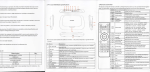
The Stub Axle Ca rrier illustration, Fig. 20, on Page J . 20 of the
Service Manual for the above cars, incorrectly quotes a dime nsi on of
3.133" (7.95 em.) between the s tub axle mounting face and the cen tre
of the top swivel bore.
This should r eao 3.1 57 11
(
7. 96 em. ) •
Jaguar Cars Limited 2005
JAGUAR
SERVICE BULLETIN
Number J. 21
Section Front Suspens ion
Sheet 1 of 3
Date March, 1 967
STEERII\C GEOMETRY
(ALL 1\UDELS)
An improved method has now been formulated for checking the Castor
and Camber angles on all cars.
This me thod, detailed below, ens ure s that the c ar is loc ked in the
mid-laden position which has been adopted as the Datum line and should
be used for all future checking operatLons.
Castor Angle Adj ustment
~:;::::==:::::----~--""
Befor e checking t he c a stor angle, exam.ine all rubber/steel bushes
for signs of dete rioration or distorti on.
Check the upper and l ower wi shbone ball j oints for exce ssive wear;
check the shock absorbe r s and mountj ngs.
Check tyre pressures.
Ensure that standing height is equal on both- side s of the car.
Make up two setting blocks and links t o the dimensions shown in
the following illustrations, according to t he c ar to be checked.
Lock the front of the c ar in the mid-l aden position by compressing
the front suspension and place the setting blocks, where applicable,
under the upper wishbone adjacent to t he bump s top r ebound rubber and
over the bracket welded to the bot tOOl of the "turret" as illustrated.
Note:
'E 1 Type cars are loc ked by links and not be blocks (see
illustration).
Using special links, lock the r e ar suspens1on in the mid-laden
position.
To fit the rear setting link, hook one end over the body br acket,
or in the c ase of car s with independent r e ar suspensi on, in the lower
hole of the rear mounting.
Depress the body and attach the oppos ite
end of the setting link (see illustration for me thod of f i tting).
Jaguar Cars Limited 2005
Check the castor angle by the nonnal me thod, usi ng an a pproved
gauge to the figures quoted in the appropriate Service Manual.
Bulletin No. J.21
March, 1967
Page 2 of 3
Camber Angle Adjustment (Front)
Proceed as detailed for Castor Angle and check with an approved
gauge to the figures quoted in the appropriate Service Manual.
Camber Angle Adjustment (Rear - Independent Suspension only)
Proceed as detailed for Castor Angle and check with an approved
gauge to the figures quoted in the appropriate Service Mahua l.
JAGUAR
l
Ml< 10
420G
'
B
~~===::----=---==~J
~ - - ------A ·-
~~- 1
C i
JAGUAR
INCHES
7"
-2%''
-Y.t~
MI;T~IC
c
f-
17·78cr.c
6·6£~-~
6· 3MM
Ml< 2.
'S'TYPE.
420 .
Jaguar Cars Limited 2005
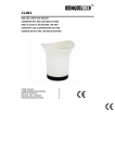
Bulletin No. J.21
March, 1967
Page 3 of 3
A
E
0/~
'E'TYPE.
JAGUAR 'S'TYPE.
300
, ..
MK 10.
INCHES
~ ~~-~~f--e 3,,~·
c
D
E
F
~--
~--
-
't.i'RAD
..
420.
420G.
METRIC
22·9cm
20-79cm
~·3mm
11
r6
I·Stnm
7·Jmm
19,32RAD IS·Omm
-9132'
·---- -- ·-· ·-· --------·-··---------A- ----·····-----·- ··--·· -·-F
--~
.----· ~--·· G
-
LJ-~[
c
..,
~ ~
-
~~~
..
f;-l
T--m~ -
G...
--·- E
H
·x·
Jaguar Cars Limited 2005
JAGUAR
SERVICE BULLETIN
Number J .23
Section Front Suspension
P:tge t of 1
Date J anuary, 1 968
Amendment to Service Bulletin J.21
Service Bulletin J.2t (page 3 of 3) incorrectly quotes the
length (dimension 'H') of the Rear Suspension Link for Mark 2 cars
as 13-7/ 1611 (37.14 em.).
Please alter your copy of J . 21 t o read
H 13-7/ 16" (34.\4 em.)
.JACU~I
Jaguar Cars Limited 2005
JAGUAR
SERVICE BULLETIN
Number L2
Section Rear Suspenaion
Sheet 1 (of 1)
Date NoT•ber, 1960
PANBARD BOD ADJUS'DD!NT
(2.4, 3.4 litre (Vark 1) and all Jlark 2 moclela)
It ia pointed out that the origi.Dal method of setting the Panbard rod by adjusting the rod to a specified length ia no longer
reocmDended.
The oorreot aethod of setting the panha.rd rod is aa
followa:•
Ensure that the
run
weight of the oar is on the wheels.
Plaoe a straight edge across one rear tyre and check the
distance to the flange of the chassis aide Dl8ber at the point at which
the rear spring centre clamping plate is bolted; repeat for the other
aide.
The point of the ohaaais side DUIDber flange at which the
dimension should be taken i s between the two bolts which secure the rear
aprin8 centre alampi.Dg plate.
'l'he dimenaion at each aide (A, in illuatra.tion) Dllst be the aaae.
U they are not, adjust the leng~ of the peDhard rod untU the two
dimensions are equal by rotating the panbard rod tube with a pair o~
grl.pa.
Fully tighten the securing nut at the rear axle brackl!lt aDd
reobeck the adjustment.
~~ tighten the 111t look:i.Dg the adjuatiDg pieoe to the panbard ~ tube.
Note:
The rear tyrea DUst be ot the same type and set at the aame
presaure when oarr,yiDg out thia chealt.
/Contimted•••
Jaguar Cars Limited 2005
Jaguar Cars Limited 2005
JAG -U AR
SERVICE
BULLETIN
Number K.6
Section Rear Suspension
Sheet 1 (of 1)
Date October, 1962.
GAS CELL TYPE REAR DAMPERS
Model affected
Commencing Chass1s Numbers
R.H.Drive
L.H.Drive
300770
351196
Mark 10
Commencing at the above chassis numbers a new type damper
(Part No: C.20606) ,incorporating a gas cell to reduce "fade" under
extreme conditions is introduced. The damper has the same setting
and is similar in outwara appearance to the early type. The
new type damper is freeLy interchangeable with the previous type
fitted.
Spares Bulletin No: J.l9
/I
MODIFIED REAR SUSPENSION CROSSBEAM
Model affected
Conmeuc1ng Chassis Numbers
R.H.Drive
Mark 10
Also introduced on 3
individual cars.
)
)
L.H.Drive
300981
351388
300718
351135
351263
Commencing at the above chassis numbers the mountings,
situated at the front and rear of the crossbeam, (see illustration
ov~rleaf) are re-positioned.
The new crossbeam (Part No: C.20174) can only be fitted to
cars having the modified body rear frame brackets. (See Service
Bulletin N.l9).
Spares Bulletin No: J.22 refers.
Jaguar Cars Limited 2005
Jaguar Cars Limited 2005
JAGUAR
SERVICE
BULLETIN
Number K.6. (2nd issue)
Section Rear Suspension
Sheet l ( of 1 )
Date January, 1963.
This Service Bulletin supersedes the original is sue of
October 1962 which should be destroyed.
GAS CELL TYPE REAR DAMPERS
Models affected
Commencing Chassis Numbers
Mark 10
2. 4 litre Mark 2
3.4 litre Mark 2
3.8 litre Mark 2
R.H.Drive
L.H.Drive
300770
114349
161805
209725
351196
127012
178844
222048
Co~nencing at the above chassis numbers a new type damper
Mark 10 (Part No. C. 20606) and Mark 2 ( Part No. C.20990) incorporating
a gas cell to reduce "fade" under extreme conditions is introduced.
The damper has the same setting and is similar in outward appearance
to the early type. The new type damper is freely interchangeable with
the previous type fitted .
Spares Bulletins No. J.l9 and J .26 refer.
MODIFIED REAR SUSPENSION CROSSBEAM
Commencing Chassis Numbers
Model affected
R.H.Drive
L.H.Drive
Mark 10
300981
351388
~ so
300718
351135
351263
introduced on 3 )
individual cars.
)
Commencing at the above chassis numbers the mountings,
situated at the f ront and rear of the crossbeam, (see illustration
overleaf) ~re re-positioned.
The new crossbeam (Part No . C.20174) can only he fit ted to
cars having the modified body rear frame brackets. (See Se rvice
Bullet.in N.19).
Spares Bulletin No . J.22 refers .
Jaguar Cars Limited 2005
Jaguar Cars Limited 2005