1
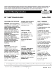
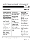
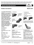
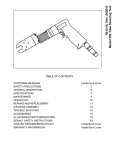
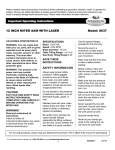
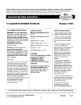
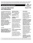
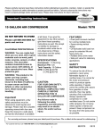
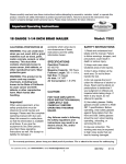
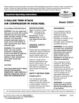
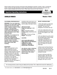
ELECTRONIC WALL SAFE
Model: 52539
SCHEMATIC DRAWING OF CASE
CAUTION: All drawings in this manual have been prepared based on the EA.
The exterior design or component positions of other models may be different
from what is indicated in the drawings, but the operation method is the same.
For Customer Service, call 1-800-348-5004 or email [email protected]
88052178
06/12
CAUTION: Upon first opening,
users can open the safe with
the emergency key (refer to
the “OPENING THE SAFE
WITH THE EMERGENCY
KEY“ section).
OPENING YOUR SAFE FOR
THE FIRST TIME
Remove the cover that
conceals the emergency lock,
and then insert the emergency
key and turn counter
clockwise.
Turn the knob clockwise the
open the door.
INSERTING THE BATTERIES:
1. Open the door
2. Remove the battery
compartment cover
3. Insert 4 AA batteries into the
battery compartment
4. Replace cover
5. If both of the red and the
green lights are on or the
electronic magnet doesn’t
work
properly, it means the voltage is
low and you should insert
new batteries.
[email protected]
Replace 4 fresh batteries
by lining them up in a
manner as indicated
by the “+” and “-” signs.
OPENING DOOR
Input your security code (3
to 8 digits) each key will
respond when pressed.
Press “A” or “B” (”C” or
“E”) buttons. (Refer to
“SETTING THE USER
CODE”)
The Correct code
combination is indicated by
an illuminated green light.
When the green light is
activated, turn the knob
clockwise within 5
seconds.
The door will open.
NOTE: The initial code is
“159”. Please input the
code again if the yellow
light flashes with three
buzzer beeps, which
means the door has failed.
CLOSING THE DOOR
Turn the knob counter
clockwise to close the
door.
2
AUTOMATIC LOCK
3 continuously wrong entries
will activate the warning beep
for 20 seconds
CAUTION: The key pad will be
disabled during beeping. You
can only stop the beeps by
opening the safe with an
emergency key and powercutting the battery.
SETTING THE USER CODE
Press the Reset button, which
will trigger a yellow light. This
indicates that it is in the state
of code setting.
Enter a new code (3-8 digits)
and press the “A” or “B” (”C” or
“E”) button to confirm with 1
buzzer beep. This
indicates the acceptance and
storage of the new code. If the
yellow light flashes with 3
buzzer beeps, this means the
code change was not effective,
and you need to try again.
OPENING THE SAFE WITH
THE EMERGENCY KEY
Remove the cover of the
emergency lock. Insert the
emergency key, turn counter
clockwise,
then turn the knob clockwise to
open the door.
Installation
1.The instructions below
apply only to installation in a
wall with wood studs.
Installation involving a
different type of wall will
require other procedures or
professional installation.
2.Choose where you want to
mount the Safe. A wall that
does not border the outside
of the structure will provide
an added layer of security.
The four Screws are for
mounting in concrete or
masonry. If you are going to
mount to another surface,
you must supply the
appropriate hardware.
3.The Wall Safe has predrilled holes in each side for
mounting in between two
wall studs. Before mounting
or drilling, make certain that
the space the safe will be
mounted in is of sufficient
depth and width to encase
the Wall Safe.
4.Open the safe
5.Wall studs are generally
located at 16” intervals,
center stud to center stud.
Use a Stud Finder(not
included) to locate existing
studs. If the existing studs
are not located at 16”
intervals, use wood blocks or
top and bottom support
brackets (not included) to
support the Wall Safe.
[email protected]
6.Use a piece of paper to
create a template using the
back of the Wall Safe. Once
you have created the
template, set it at the desired
space on the wall. Use a
carpenter’s level to set the
template evenly in place.
7.Make certain the work area
is free of furniture and any
items that my get damaged by
dust from drilling. Turn off the
circuit breaker for the area you
are working in to avoid danger
from coming into contact with
any existing wiring.
8.Nail into the wall in the
center of the section to be
pulled out and use portion of
the wall. Use a drywall saw or
jig saw to cut out the section
of wall as outlined by the
template. Depending on the
depth of the safe in relation to
the depth of walls, you may
need to cut through two walls
to allow for the depth of the
safe - the wall nearest you
and the one behind it.
9.Situate the Safe where you
want it and draw marks
through the four mounting
holes onto the mounting
surface(s). Move the Safe and
predrill the holes for the
Screws. Set the Safe in place.
If it does not fit snugly, add
shims which can be nailed to
the wall studs.
3
10.Thread the Screws into
place. Turn the expansion
bolts counterclockwise to
separate. Use the expansion
bolts to secure the case to
the wall, and then tighten all
screws.
CAUTION: Use the
expansion bolt when there is
a concrete wall surface. Use
the clamping screw(not
included) when there is a
wooden wall surface.
DO NOT RETURN TO STORE
North American Tool Industries (NATI) makes every effort to ensure that this product meets high
quality and durability standards. NATI warrants to the original retail consumer a 1-year limited
warranty from the date the product was purchased at retail and each product is free from defects in
materials. Warranty does not apply to defects due directly or indirectly to misuse, abuse, negligence,
or accidents, repairs or alterations, or a lack of maintenance. NATI shall in no event be liable for
death, injuries to persons or property, or for incidental, special, or consequential damages arising from
the use of our products. To receive service under warranty, the original manufacturer part must be
returned for examination by an authorized service center. Shipping and handling charges may apply. If
a defect is found, NATI will either repair or replace the product at its discretion.
[email protected]
4
Coffre-fort Mural Électonique
Modèle 52539
corps de coffre-fort
L`aspect de coffre-fort est en type EA,mais les panneaux frontals et les accessoires
des autres produits séries peuvent être différents du type EA,veuillez se référer aux
produits réels,mais les méthodes de fonctionnements sont identiques.
Service tél: 1-800-348-5004
mél: [email protected]
88052178
06/12
ATTENTION: Lors de la
première ouverture, les
utilisateurs peuvent ouvrir le
coffre avec la clé de secours
(Reportez-vous à la section "
OUVERTURE PAR CLÉ DE
SECOURS).
OUVERTURE DE VOTRE
COFFRE-FORT POUR LA
PREMIERE FOIS
1.Enlevez le couvercle de la
serrure d`urgence,puis insérez
la clé d`urgence et la tournez
dans le sens inverse des
aiguilles d`une montre.
2.Insésez la clé principale(ou le
bouton-volant ),la tournez dans
le sens des aiguilles d`une
montre pour ouvrir la porte.
CHANGE DES PILES
1. Ouvrez la porte
2. Insérez 4 AA piles basiques
dans le compartiment de la
batterie,et puis fermez le
couvercle.
3. En vertu de l`état normal,si
les feux rouges et les feux
verts sont allumés en même
temps,cela signifie que la
tension est faible et vous
devrez insérer de nouvelles
piles(les directions de pôle
positif et de pôle négatif
doivent être correctes
),après avoir changé les
piles,répétez I`opération une
fois de nouveau,si pas de
phénomène anormale,ferez
la porte.
[email protected]
ATTENTION:Remplacez les
4 nouvelles piles selons les
indications de symboles “+”
et ”_” dans le comparitiment
de la batterie.
OUVERTURE DE LA
PORTE
1.Saisissez votre code de
sécurité (chiffres de 3 à 8
),appuyez sur la touche “A”
ou “B” ( “C” ou “E” )pour
confirmer.
2.Avec un signal sonore bip,
er le voyant vert à LED
aluume ,cela indique que le
mot de passe est correct , à
ce moment vous avez 5
secondes pour ouvrir la
porte en tournant le bouton
de réglage dans le sens des
aiguilles d`une montre ou
par la clé principale,si vous
dépassez ce temps,la porte
sera verrouillée
automatiquement.
3. Avec trois signaux
sonoires bip,et le voyant
jaune à LED clignote,cela
indique que le mot de passe
n`est pas correct,veulliez
saisir le mot de passe de
noveau,puis appuyer sur la
touche “A” ou “B” (“C” ou
“E” )pour confirmer.
ATTENTION:le mot de
passe initial de ce produit
est 159.
2
Verrouillage automatique
1.Si vous avez saisi trois fois de
mot de passe en continu, et le mot
de passe n’est pas correct, le
système de produit sera
automatiquement verrouillé
pendant 20 secondes. Et le
buzzer sera donné l’alarme
intermittent et le voyant jaune sera
clignoté.
2.Attention:pendant le verrouillage
automatique. Le système ne peut
pas fonctionner.
Mot de passe personnalisé
1.Ouvrir le coffre-fort et appuyez
sur la touche rouge de
transcodification dans l’intérieur
de coffre-fort, à ce moment, le
voyant jaune allumera, cela
indique que vous avez entré
2.Dans l’état de changement de
mot de passe
3.Entrez le mot de passe de
l’utilisateur (chiffres de 3 à 8) et
appuyez sur la touche “A” ou “B”
(“C” ou “E”)pour confirmer, avec
deux signaux sonores bip, cela
indique le nouveau mot de passe
d’utilisateur est accepté et
sauvegardé.
4.Si le voyant jaune clignote et le
buzzer émet trois sons bip, ce qui
signifie que le changement de mot
de passe n’est pas bon, et vous
devez essayer de nouveau.
OUVERTURE PAR CLÉ DE
SECOURS
Installation
1. Les instructions ci-dessous
s'appliquent uniquement à
l'installation dans un mur avec
des poteaux en bois. Les
installations concernant les
autres types de mur demandent
d'autres procédures ou
installations professionnelles.
6. Utilisez un morceau de papier
pour créer un modèle utilisant le
dos du coffre-fort mural. Une fois
que vous avez créé ce modèle, le
mettez à l'espace désiré sur le
mur. Utilisez un niveau de
charpentier pour mettre le modèle
uniformément en place.
2. Choisissez où vous voulez
monter le coffre-fort. Le mur sans
frontière extérieure de la
structure offre une couche de
sécurité supplémentaire. Les
quatre vis de montage sont en
béton ou en maçonnerie. Si vous
allez monter sur une autre
surface, vous devez fournir le
matériel adapté.
7. Assurez-vous que la zone de
travail soit exemptée de mobiliers
et des objets qui pourraient être
endommagés par le poussière du
forage. Débrancher le disjoncteur
de circuit de la zone dans laquelle
vous êtes en train de travailler
pour éviter le danger du contact
avec le câblage existant.
8. Vissez dans le mur au centre
3. Le coffre-fort mural a des trous de la section à être tirée et utilisez
pré-percés à chaque côté pour le la portion du mur. Utilisez une scie
montage entre deux poteaux de à cloison sèche ou une scie
mur. Avant de monter ou de
sauteuse pour couper la section
forer, assurez-vous que l'espace de mur suivant ce qui est indiqué
dans lequel le coffre-fort sera
par le modèle. D’après la
monté a la profondeur et la
profondeur du coffre-fort en
largeur suffisantes pour
rapport avec la profondeur des
envelopper le coffre-fort mural.
murs, vous devriez peut-être
couper à travers deux murs pour
4. Ouvrez le coffre-fort.
permettre la profondeur du coffrefort - le mur le plus proche de
5. Les poteaux muraux sont
vous et lequel derrière lui.
généralement situés aux
intervalles 16", du poteau central 9. Situez le coffre-fort où vous
au poteau central. Utilisez un
voulez et faites les marques à
détecteur de poteaux (non inclus) travers les quatre trous de
pour localiser les poteaux
montage sur la surface de
existants. Si les poteaux
montage. Déplacez le coffre-fort
existants ne sont pas situés aux et pré-percer les trous pour les
intervalles 16", utilisez des blocs vis. Mettez le coffre-fort en place.
en bois ou consoles de support
S’il ne rentre pas bien ajusté,
supérieure et inférieure (non
ajouter des cales qui peuvent être
inclues) pour soutenir le coffreclouées aux poteaux de mur.
fort mural.
[email protected]
3
10.Vissez les vis en place.
Tournez et ouvrez le boulon
d`expansion dans le sens des
antihoraire. Utilisez les
boulons d`expansion pour
sécuriser la connexion entre le
coffre-fort et le mur. Après
avois confirmé le montage,
puis serrez tous les vis.
ATTENTION:Utilisez le boulon
d`expansion quand il y a une
surface de mur en béton.
Utilisez la vis de serrage
quand il y a un surface de mur
en bois.
DO NOT RETURN TO STORE
North American Tool Industries (NATI) makes every effort to ensure that this product meets high
quality and durability standards. NATI warrants to the original retail consumer a 1-year limited
warranty from the date the product was purchased at retail and each product is free from defects in
materials. Warranty does not apply to defects due directly or indirectly to misuse, abuse, negligence,
or accidents, repairs or alterations, or a lack of maintenance. NATI shall in no event be liable for
death, injuries to persons or property, or for incidental, special, or consequential damages arising from
the use of our products. To receive service under warranty, the original manufacturer part must be
returned for examination by an authorized service center. Shipping and handling charges may apply. If
a defect is found, NATI will either repair or replace the product at its discretion.
[email protected]
4