1
CRS-170A L-Band 1:1 Redundancy Switch
Connector Pinouts
5.4
Revision 3
MN/CRS170A.IOM
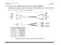
J4 Control Connector (Bottom) – Modem ‘B’, DB-9F
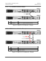
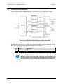
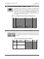
The Modem ‘B’ Control connector is a 9-pin Type ‘D’ female interface
located on the modem side of the CRS-170A L-Band 1:1 Redundancy Switch
module. Refer to Table 5-3 for pin assignments. Pins 2, 3, and 4 carry signals
looped through the switch module from Modem A to Modem B, while pins 6,
7, and 8 loop the same signals from Modem B through to Modem A. The
12VDC input, which is diode OR’ed with the corresponding 12VDC input
from Modem A, powers the switch module.
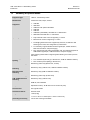
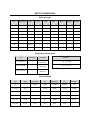
Table 5-3. J4 - Modem ‘B’ Control Connector Pin Assignments
Pin #
1
2
3
4
5
6
7
8
9
5.5
Signal Function
Signal Name
Direction
Signal Ground
Modem A Tx Comm
Modem A Clk Out
Modem B Online
Signal Ground
Modem B Tx Comm
Modem B Clk In
Modem B Serial Faults
+12 VDC
Ground
AUX_SER_TX_A
CLK_OUT_A
ONLINE_B
Ground
AUX_SER_TX_B
CLK_IN_B
SERIAL_FAULT_B
+12VDC
Out
Out
Out
In
In
In
In
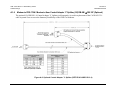
Antenna Side Type ‘N’ Connectors – J7 (Rx) and J8 (Tx)
The 50Ω female Type ‘N’ connectors on the antenna side of the CRS170A L-Band 1:1 Redundancy Switch module provide the coaxial
cable connections to the outdoor receive and transmit equipment (BUC
and LNB).
Table 5-4. J7 (Rx) and J8 (Tx) Type ‘N’ Connectors
Type ‘N’
Connector
Reference
RX
TX
Description
Direction
J7
RF Input
LNB 10 MHz Ref
LNB Power
In
Out
Out
J8
RF Output
BUC 10 MHz Ref
BUC FSK
Comm.
Out
Out
In/Out
Out
5–3