1
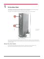
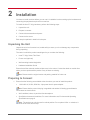
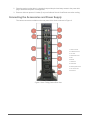
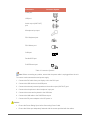
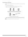
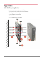
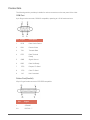
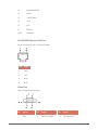
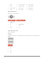
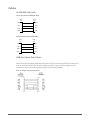
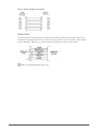
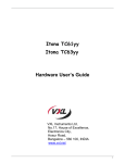
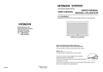
Itona TC63yy Hardware User Guide Copyright © 2004-2013 VXL Instruments Limited. All Rights Reserved Information in this document is subject to change without notice and does not represent a commitment on the part of the manufacturer. No part of this guide may be reproduced or transmitted in any form or means, electronic or mechanical, including photocopying and recording, for any purpose, without the express written permission of the manufacturer. Every effort has been made to make this guide as complete and as accurate as possible, but no warranty or fitness is implied. The authors and the publisher shall have neither responsibility nor liability to any person or entity with respect to loss or damages arising from the use of information contained in this guide. This disclaimer does not apply in countries where such provisions are inconsistent with local law. All Trademarks are acknowledged. Last Updated: September, 2012 Version: TC63yy/UG-37-12 VXL Instruments Ltd, House of Excellence, No. 17, Electronics City, Hosur Road, Bangalore– 560 100, INDIA www.vxl.net Federal Communication Commission (FCC) Statement This equipment has been tested and found to comply with the limits for a Class B digital device, pursuant to Part 15 of the FCC Rules. These limits are designed to provide reasonable protection against harmful interference in a residential installation. This equipment generates uses and can radiate radio frequency energy and, if not installed and used in accordance with the instructions, may cause harmful interference to radio communications. However there is no guarantee that interference will not occur in a particular installation. If this equipment does cause harmful interference to radio or television reception, which can be determined by turning the equipment Off and On, the user is encouraged to try to correct the interference by one or more of the following measures: Re-orient or relocate the receiving antenna. Increase the separation between the equipment and receiver. Connect the equipment to an outlet on a circuit different from that to which the receiver is connected. Consult the dealer or an experienced radio / television technician for help. Each Thin Client is equipped with a FCC compliance label that shows only the FCC identification number. The full information of the associated label is as follows: This device complies with Part 15 of the FCC rules. Operation is subject to the following two conditions: 1. This device may not cause harmful interference. 2. This device must accept any interference received, including interference that may cause undesired operation. i Regulatory Certifications ii Table of Contents Federal Communication Commission (FCC) Statement i Regulatory Certifications ii 1 1 Introduction About the User Guide 1 Abbreviations and Acronyms 2 Chapters in the Manual 2 2 Installation 4 Unpacking the Unit 4 Preparing to Connect 4 Connecting the Accessories and Power Supply 5 Connecting to the Server 7 3 4 Specifications 8 Hardware 8 Mechanical 8 Environmental Operating 8 Electrical – External Power Adapter 9 Troubleshooting Appendix 10 11 iii 1 Introduction Thin Clients are terminal devices that connect to multi-user application servers operating under Citrix MetaFrame and Windows Server 2000/2003 operating systems. This guide covers installation procedure and hardware details of Itona TC 63yy series.. 1. Power Button. 2. USB Ports. Figure 1: ItonaTC63yy Itona TC63yy deliver smart and robust solutions for Thin Client computing. They are aesthetically and ergonomically designed compact desktop. Itona series thin clients offer fanless CPU solution to enhance reliability. About the User Guide This User Guide provides step by step instructions to install Itona D series hardware. The specifications and troubleshooting steps are also included in this User Guide. 1 Introduction Abbreviations and Acronyms Abbreviation Expansion AC Alternating Current DC Direct Current LAN Local Area Network LED Light Emitting Diode TCP/IP Transmission Control Protocol/Internet Protocol USB Universal Serial Bus VESA Video Electronics Standards Association VGA Video Graphics Array Table 1: Abbreviations and Acronyms Chapters in the Manual Chapter No Chapter Name Description 1 Introduction Contains an overview of the product, information about this guide and abbreviations used in this guide. 2 Installation Contains the procedure to set up the hardware. 3 Specifications Contains hardware, mechanical, electrical, interface and operating environment specifications 4 Troubleshooting Contains solutions to problems that you may encounter while using the product. — Appendix Contains detailed specifications for connectors and cables used with the product. Table 2: List of Chapters Warning Introduction Do not open enclosure, hazardous voltages present inside equipment. Any changes or modifications not expressly approved by the party responsible for compliance could void the user's authority to operate this equipment. There is no user serviceable part inside. Do not open enclosure, hazardous voltages present in the equipment’s components. Do not disassemble the equipment as this can nullify your warranty. 2 This equipment must be earthed to prevent accidental electric shocks, connect a three pin connector to ensure adequate earthing. As a precaution, the AC socket outlet should be near the equipment and should be easily accessible. Sound Power Level is less than 60dB (A), when measured according to ISO 7779. Caution 3 Ensure that all expansion slots (on the back or side of the client) are covered with metal retaining brackets, and tightly attached to the computer cabinet. Only equipment certified to comply with Class B (computer input/output devices, terminals, printers etc.) should be connected to this equipment, and must have shielded interface cables. This equipment should not be used in electro-medical applications. Do not operate this equipment in corrosive or explosive atmosphere. Operate this equipment within specified temperature limits. Introduction 2 Installation You have to install the client before you can use it. Installation involves setting up the hardware and connecting the peripherals required for normal use. To install the Itona TC 63yy hardware, perform the following steps: 1. Unpack the unit. 2. Prepare to connect. 3. Connect the accessories and power. 4. Connect to the server Each step is explained in detail in this chapter. Unpacking the Unit Unpack the unit from its carton box, handle safely to ensue you do not damage any components during unpacking. The carton in which the product was shipped to you contains the following: Itona TC 63yy Series Thin Client Power cord (optional) Wall mounting bracket-single side Hardware Installation Guide Ensure that all the contents mentioned above are in the carton. Contact the dealer or reseller from whom you have purchased the product if any of those are missing. Note: Please retain the original carton and packing material for future use. Preparing to Connect 1. Ensure that the following are available at the site where you want to install the product. 100~240V AC, 0.65A, 50/60 Hz, 3-pin power inlet for power adapter . Note: Ensure that the power inlet plug is regulated and earthed. A floating ground/chassis could cause an electric shock. Well ventilated, clean, dry and dust free atmosphere. Specified environmental conditions. For more information see, Environmental Operating Specifications on page 8. Note: The product can only be used in vertical position. Do nor placed it flat on a desk as it will block the air vents and heat up. Installation 4 2. Place the product on the table in a location that provides quick and easy access to the power Inlet plug to shutdown the power in emergencies. 3. Ensure a minimum space of 2 inches (5 cm) on all sides of the unit for efficient convection cooling. Connecting the Accessories and Power Supply The various connectors available on the rear panel of the client are shown in Figure 2. 1. Audio Line Out 2. 2x Ethernet Ports. 3. LPT Port 4. PS/2 Mouse Port 5. MIC 6.4xUSB 7. COM Port 8. SVGA Port 9. PS/2 Keyboard Port 10. AC Power Out Ac Power IN Figure 2: Itona TC63yy Series Rear View 5 Installation Connectors Connector Symbol Video port USB port Audio output (LINE OUT) port Microphone input port PS/2 Keyboard port PS/2 Mouse port COM port 1 Parallel/LPR port RJ45 Ethernet port Table 3: Connector Symbols Note: Before connecting any cables, ensure that the power cable is unplugged from the unit. To connect various accessories and power supply: 1. Connect the DVI cable from your display unit to the DVI-I port. 2. Connect the USB devices to the USB ports. 3. Connect the external powered speakers to the audio output (LINE OUT) port. 4. Connect the microphone to the microphone input port. 5. Connect the mouse and keyboard to the USB slots. 6. Connect the LAN cable to the RJ45 Ethernet port. 7. Connect the DC power adapter to the DC power in. Caution: Installation Ensure the Power Rating Spec before Connecting Power Cable. Ensure that Video port adequately fastened with the screws provided with the cables. 6 Connecting to the Server The Thin Client can be physically connected to the server/network by connecting to LAN through TCP/IP. To connect client to LAN through TCP/IP: 1. Connect one end of a 10/100/1000 cable to the Ethernet LAN port of the client. 2. Connect the other end to a LAN hub as shown in Figure 3. Figure 3: LAN Connection through TCP/IP 3. Press the power button to switch on the ItonaTC15yy series thin client. The front panel LED lights up and the client starts with a beep sound. The Connection Manager screen appears. Note: To configure the client, refer to the Software User’s Guide. 7 Installation 3 Specifications Hardware Processor Intel Atom N270 1.6 GHz VGA Memory Shared Video Memory 64MB min, 128MB max. Flash IDE 44 Pin RAM 128MB ~ 2GB DDRII 533/667 Networking1 10/100Mbps Networking 2 10/100/1000Mbps Power Supply Internal Power Supply Display Resolution 16/32 Bits 1920x1200 @60Hz max Mechanical Product Dimension Height 1268mm Width 50 mm Depth 250 mm Weight 3,.0 Kg (max) Environmental Operating Specifications o o Operating temperature + 5 C to +40 C Storage temperature - 20o C to +60oC Humidity 20% to 80% RH Max noncondensing 8 Electrical – External Power Adapter Line Voltage 100V to 240V AC (+6, -10%) Line Frequency 50 / 60 Hz Power Inlet 1.2A, 3-pin power plug (IEC 320) Power Oulett 3-pin power socket (IEC 320 ) For devices upto 0.30A max., 100VAC~50/60Hz. For devices upto 0.12A max., 240VAC~50/60Hz. MTBF 9 >50,000Hrs Specifications 4 Troubleshooting This chapter contains solutions for problems you may encounter while using the product. Problem Solution The power-LED on front panel does not glow when the client is switched on. Ensure that the power cord is plugged into an AC outlet. There is no display on the monitor, though the powerindicating LED glows. Ensure that the video cable is properly connected.. The mouse (or keyboard) does not work when the client is switched on. Ensure that the mouse (or keyboard) is plugged into the correct PS/2 port on the rear panel. Troubleshooting Check the fuse in the power-plug, if available. 10 Appendix Side Wall Mounting Bracket To install single side wall mounting bracket for TC63yy: 1. Drill four holes on the wall and insert four M7x33 wall plugs.. 2. Place Single Side Wall Mounting Bracket 3. Fix the four M4x24 self taped screws. 4. Place the Unit 5. Fix the fourM3x8 thumb screws M3x8. 11 Appendix Connectors The following section provides pin details for various connectors on the rear panel of the client. COM Port 9-pin D-type male connector, RS232C compatible, operating at 115.2K baud maximum. Pin Signal Description 1 DCD Data Carrier Detect 2 RxD Receive Data 3 TxD Transmit Data 4 DTR Data Terminal Ready 5 GND Signal Ground 6 DSR Data Set Ready 7 RTS Request To Send 8 CTS Clear To Send 9 NC Not Connected Printer Port(Parallel) 25-pin D-type female connector. ECP/EPP compatible. Pin Appendix Signal 1 STROBE 2-9 DATA 0 – 7 12 10 ACKNOWLEDGE 11 BUSY 12 PAPER END 13 SLCT 14 AFD 15 ERROR 18-25 GROUND 10/100/1000 Ethernet LAN Port RJ-45 modular 8-pin jack. 10/100/1000 Mbps. Pin Signal 1 TxD+ 2 TxD- 3 RxD+ 6 RxD- Video Port 15-pin D-type female connector. 13 Pin Signal Pin Signal Pin Signal 1 Red 6 Red return GND 11 No Connection Appendix 2 Green 7 Green return GND 12 No Connection 3 Blue 8 Blue return GND 13 Horizontal Sync 4 No Connection 9 No Connection 14 Vertical Sync 5 GND 10 No Connection 15 No Connection Mouse/keyboard Port PS/2 Mouse / Keyboard connector. Pin Signal Pin Signal 1 Mouse/Keyboa rd data 4 VCC 2 NC 5 Mouse/Keyboard clock 3 GND 6 NC Audio / Microphone Port Standard audio jacks. USB Port 4-pin series-A receptacle. 4~ 5 ports depending on the model. Both USB1.1 and USB2.0 models are available Appendix Pin Signal 1 VCC 2 D- 3 D+ 4 GND 14 Cables 10/100/1000 LAN Cable Cross Connection-(Without Hub) RJ45 Pin RJ45 Pin TXD+ 1 3 RXD+ TXD- 2 6 RXD- RXD+ 3 1 TXD+ RXD- 6 2 TXD- Straight Connection-(With Hub) RJ45 Pin RJ45 Pin TXD+ 1 1 TXD+ TXD- 2 2 TXD- RXD+ 3 3 RXD+ RXD- 6 6 RXD- COM Port (Serial Port) Cables Serial devices like modems and printers use 25 pin D-type connectors for RS232 connections. In order to connect an RS232 device with a 25-pin connector, 9-pin connector signals must be converted to 25-pin connector signals as shown in the following diagram. 9-pin to 25-pin Cross Connection 15 Appendix 9-pin to 25-pin Straight Connection Printer Cable The following table shows the pin connections of the Standard Centronics parallel cable. Some manufacturers change pin functions or polarity on their printers. For such printers, custom cables may be necessary. Refer to your printer manual for cabling information in such cases. Note: Use certified shielded cables only. Appendix 16