1
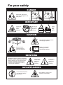
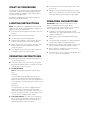
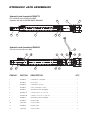
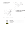
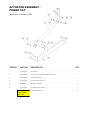
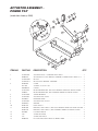
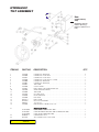
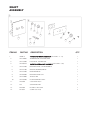
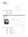
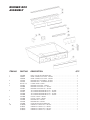
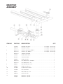
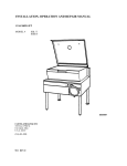
Operators Manual
Installation, Operation & Service
Skillets
OPEN BASE & MODULAR
GAS SKILLETS MODELS
SGL-30-TR
SGL-40-TR
SGM-30-TR
SGM-40-TR
BULLET FOOT (FRONT) 078160-1
FLANGED FOOT (BACK) 078161-1
™
Cleveland
Enodis
1333 East 179th St., Cleveland, Ohio, U.S.A. 44110
Phone: (216) 481-4900 Fax: (216) 481-3782
Visit our web site at www.clevelandrange.com
SE95033 Rev. 5
FOR THE USER
FOR YOUR SAFETY
DO NOT STORE OR USE
GASOLINE OR ANY OTHER
FLAMMABLE LIQUIDS AND
VAPOURS IN THE VICINITY
OF THIS OR ANY OTHER
APPLIANCE.
WARNING: Improper installation,
adjustment, alteration, service or
maintenance can cause property
damage, injury or death. Read the
Installation and Operating
instructions thoroughly before
installing or servicing this
equipment.
IMPORTANT
Post in a prominent location, instructions to be followed in the event the user smells gas.
This information shall be obtained by consulting your local gas supplier.
Keep appliance area free and clear from combustibles.
Do not obstruct the flow of combustion and ventilation air.
All service must be performed by a qualified cleveland range technician.
For unit equipped with casters, the installation shall be made with a connector that complies
with the Standard for Connectors for Movable Gas Appliances, ANSI Z21.69 or Connectors
for Moveable Gas Appliances, CAMCGA-6.16, and a quick-disconnect device that complies
with the Standard for Quick Disconnect Devices for Use With Gas Fuel, ANSI Z21.41, or
Quick Disconnect Devices for Use with Gas Fue4 CANT-6.9. Adequate means must be
provided to limit the movement of the appliance without depending on the connector and the
quick-disconnect device or its associated piping to limit the appliance movement. A restraint
can be attached to the rear leg next to the gas connection.
For Australia, the equipment must be installed by an authorized person in accordance with
AS 5601, local authority, gas, electricity, any applicable statutory regulations and
manufacturer requirements.
RETAIN THIS MANUAL FOR YOUR REFERENCE.
For your safety
DANGER
Keep hands and utensils
away from moving parts and
pinch points.
✘
✘
IMPORTANT
Do not lean
on or place
objects on
skillet lip.
Inspect unit
daily for
proper
operation.
Lift lid
before
tilting
skillet.
1
2
CAUTION
Wear protective equipment when
discharging hot product.
Stand clear of product
discharge path when
discharging hot product.
Surfaces may be
extremely hot! Use
protective equipment.
SERVICING
WARNING: Improper installation, adjustment,
alteration, service or maintenance can cause
property damage, injury or death. Read the
installation, operating and maintenance
instructions thoroughly before installing
or servicing this equipment.
Shut off power
at main fuse
disconnect
prior to
servicing.
Ensure skillet
is at room
temperature
prior to
servicing.
GAS APPLIANCES
Do not attempt to operate
this appliance during a
power failure.
Keep appliance and area free
and clear of combustibles.
INSTALLATION
GENERAL
INSPECTION
Installation of the unit must be accomplished by
qualified installation personnel working to all applicable
local and national codes. Improper installation of unit
could cause injury or damage.
Before unpacking visually inspect the unit for evidence
of damage during shipping.
This equipment is built to comply with applicable
standards for manufacturers. Included among those
approval agencies are: UL, A.G.A., NSF, ASME/N.Bd.,
CSA, CGA, ETL, and others. Many local codes exist,
and it is the responsibility of the owner/installer to
comply with these codes.
The rating plate is located directly behind the upper
front panel (left side). For easy access, remove the two
screws securing the upper front panel and hinge the
lower front panel downwards. Gas type, burner ratings
and electrical requirements are stated on the plate.
Observe all clearance requirements to provide proper
make-up air flow. Do not obstruct the flow of combustion
and ventilation air. Check rating plate to ensure that unit
has been equipped to operate with the type of gas
available at the installation.
All units are protected with fuses which are located
inside the service box. For easy access, hinge front
panel downwards.
A pressure tap is supplied with each unit and is
installed on the manifold. The gas pressure must be
checked when unit is installed, to ensure unit gas
pressure is the same as specified on the rating plate.
For access to the pressure tap, remove front panel, turn
power switch to the 'OFF' position as a precaution and
hinge front panel downwards. The pressure tap is
located behind the front shield. If necessary, pressure
adjustments can be made at the pressure regulator
which is installed on the manifold. For easy access to
the pressure regulator, view along left side of unit from
underneath. Once pressure test is completed, turn
power switch and thermostat to the 'OFF' position. Raise
lower front panel back into position.
Make certain that new piping, joints and connections
have been made in a clean manner and have been
purged, so that piping compound, chips, etc., will not
clog valves and/ or controls. Use pipe joint sealant that
is approved for use with liquefied petroleum gas.
Have a qualified gas technician check the gas pressure
to make certain that existing gas facilities (meter, piping;
etc.) will deliver the BTU's of gas required at the unit
with no more than 1/2" water column pressure drop.
When checking pressure, be certain that all the
equipment on the same gas line is turned to the 'ON'
position.
WARNING: Always check gas connections for leaks
using soap solution or similar means. DO NOT CHECK
WITH AN OPEN FLAME.
If damage is noticed, do not unpack the unit, follow
shipping damage instructions.
SHIPPING DAMAGE
INSTRUCTIONS
If shipping damage to the unit is discovered or
suspected, observe the following guidelines in
preparing a shipping damage claim.
1. Write down a description of the damage or the
reason for suspecting damage as soon as it is
discovered. This will help in filling out the claim
forms later.
2. As soon as damage is discovered or suspected,
notify the carrier that delivered the shipment.
3. Arrange for the carrier's representative to examine
the damage.
4. Fill out all carrier claims forms and have the
examining carrier sign and date each form.
CLEARANCE
REQUIREMENTS/ DRAIN
LOCATIONS
This unit must be installed in accordance with the
clearances shown on the rating label which is adhered
to the unit.
FOR YOUR SAFETY. Keep the appliance area free and
clear of combustible materials.
VENTILATION
These units must be installed under an adequate
ventilation system.
INSTALLATION
VENTILATION
KEEP THE APPLIANCE AREA FREE AND CLEAR OF
COMBUSTIBLE MATERIALS.
A gas skillet must be installed in a location in which the
facilities for ventilation permit satisfactory combustion of
gas and proper venting. Proper ventilation is imperative
for good operation of the appliance. The ideal method
of ventilating a gas skillet is the use of a properly
designed ventilating canopy, which should extend at
least 6" (152mm) beyond all sides of the appliance
(except against a wall, if the canopy is a wall
installation). This is usually part of a mechanical exhaust
system.
1. Carefully remove unit from carton or crate. Remove
any packing material from unit.
2. A protective material has been applied to the
stainless steel panels.
NOTE: This material must be removed immediately
after installation, as heat will melt the material and
make it difficult to remove.
3. Position the unit in it's permanent location.
4. Level skillet by means of adjustable stainless steel
feet. Use a spirit level and level unit four ways;
across front and back and down left and right edges.
5. Once positioned and
4 7/8" (124mm)
leveled, permanently
120
120
secure the unit's
flanged feet to the
7/16"Ø, 3 HOLES
floor using 5/16" lag
ON 3 1/8" (80mm) B.C.D.
bolts and floor
FLANGED FOOT DETAIL
anchors (supplied by
(REAR LEGS ONLY)
the installer). Three
bolts are required to secure each of the flanged feet.
6. Seal joints of flanged feet with a silicone sealant.
GAS
Further information can be obtained by referring to the
U.S.A. National Fire Protection Association's NFPA96
regulations. These standards have also been adopted
by the National Building Code in Canada.
AIR SUPPLY
Unit shall be located so as not to interfere with proper
circulation of air within the confined space. All gas
burners require sufficient air to operate.
Large objects should not be placed in front of the unit
which might obstruct the air flow through the front. Do
not obstruct the flow of combustion and ventilation air.
Do not permit fans to blow directly at the unit and
wherever possible avoid open windows adjacent to the
appliance sides and back; also wall type fans which
create air crosscurrents within the room.
ENSURE THE GAS SUPPLY MATCHES THE
SKILLET'S REQUIREMENTS AS STATED ON THE
RATING PLATE.
ELECTRICAL
A 3/4" NPT gas connection is required along the left
side of the unit.
A cord and plug is supplied on each unit, 120 volts,
single phase, 1.0 amps.
It is recommended that a sediment trap (drip leg) be
installed in the gas supply line. If the gas pressure
exceeds 14" water column, a pressure regulator must
be installed, to provide a maximum of 14" water column
gas pressure to the gas control valve.
WARNING: Electrical Grounding Instructions:
Connect the gas supply piping. Location and pressure
data are shown on the specification sheet.
Installation must be in accordance with local codes
and/or the National Fuel Gas Code ANSI Z233.1-latest
edition (USA) or Installation Codes for Gas Burning
Appliances and Equipment CAN/CGA-B 149.1 and B
149.2 (Canada). Use a gas pipe joint compound which
is resistant to L.P gas. Test all pipe joints for leaks with
soap and water solution. Ensure that the gas pressure
regulator is set for the manifold pressure indicated on
the gas rating plate.
The appliance and its individual shut-off valve must be
disconnected from the gas supply piping system during
any pressure testing of that system at test pressures in
excess of 1/2 psi (3.45 kPa). The appliance must be
isolated from the gas supply piping system by closing
its individual manual shut-off valve during any pressure
testing of the gas supply piping system at test
pressures equal to or less than 1/2 psi (3.45 kPa).
This appliance is equipped with a three prong
(grounding) plug for your protection against shock
hazard and should be plugged directly into a properly
grounded three prong receptacle. Do not cut or remove
the grounding prong from this plug.
A separate 15 amp service must be provided. For 120V
usage, each skillet is electrically equipped with a cord
set with a three prong plug which fits any standard 120
volt three prong grounded receptacle.
When a unit is ordered and built for 208/240 volt, the
supply line must be connected to the wiring
terminations located inside the terminal box. For ease in
attaching the supply line, there is a removable cover on
the terminal box. A wiring diagram is attached to the
rear panel of each unit.
IMPORTANT: This appliance must be electrically
grounded in full accordance with local codes, or in the
absence of local codes, with the Canadian Electrical
Code C22.1 or with the National Electrical Code,
ANSI/NFPA No. 70-latest edition (whichever is
applicable).
WATER CONNECTIONS
(OPTIONAL)
CLEANING
After installation the unit must be thoroughly cleaned
and sanitized prior to cooking.
A 3/8" NPT cold water line and a 3/8" NPT hot water line
are required for the fill faucet.
OPERATING INSTRUCTIONS
3
2
1
7
xttwulql
CONTROL
PANEL
8
6
ITEM #
DESCRIPTION
FUNCTION
1.
On-Off Switch
Main power switch for unit.
2.
Power Indicator Light (Red)
Indicates power is on.
3.
Heat Indicator Light (Yellow)
Turns ON when system is calling for heat and
OFF when system is satisfied.
4.
Temperature Dial
Regulates the surface temperature of the pan.
5.
Power Tilt Switch
Used for tilting the pan up or down.
Some models have a Hand Tilt Wheel.
6.
Manual Tilt Override
Used on units with Power Tilt for tilting the pan up or down
in case of power or mechanical failure.
7.
Flue
8.
Gas Shut Off Valve
Allows you to shut the gas off to the appliance if required.
9.
Tangent Draw-Off Valve
(not shown)
Option - Used for draining product or wash water from kettle.
10.
Faucet
(not shown)
Option - hot and/or cold faucet mounts to skillet for
convenient filling of the pan.
4
5
START UP PROCEDURE
5. Turn power switch to the 'OFF' position when skillet
is not in use.
This appliance has been factory tested and adjusted
under ideal conditions but, rough handling, low gas
pressure, altitude or variations in gas characteristics
may require fine adjustment.
6. During an electrical power interruption, turn power
switch to the 'Off position. This unit cannot be made
to operate without electrical power or gas supply.
All units are equipped with fixed orifices and do not
require primary air adjustment.
OPERATING SUGGESTIONS
LIGHTING INSTRUCTIONS
NOTE: This appliance is equipped with a direct spark
ignition system. Ensure gas and electrical supply to the
appliance, are in the 'ON' position.
1. Turn the main manual gas shut-off valve to the 'ON'
position.
2. Turn power switch to the 'ON' position.
IMPORTANT: Always raise the spring assist cover
before activating the tilt mechanism. Before
commencing to cook, ensure frypan is in the lowered
position by pressing down on the tilt switch.
1. To preheat, set thermostat to desired cooking
temperature. The amber pilot light will cycle on and
off with the thermostat.
3. Set thermostat to desired temperature.
2. Allow skillet to preheat for approximately 15-30
minutes.
4. If ignition fails and/or the control system goes into
lockout, set power switch to the 'OFF" position.
3. Once preheated, insert product in skillet and adjust
thermostat to required cooking temperature.
5. Wait 5 minutes then repeat steps 1 through 3. If the
problem persists, have a qualified serviceman
check the system.
4. If desired, once product has cooked, it can be held
prior to serving at a lower temperature setting.
6. To shutdown system, turn power switch and main
manual gas valve to the 'OFF' position.
OPERATING INSTRUCTIONS
1. Ensure gas and electrical supply to the appliance
are in the 'ON' position.
2. Turn power switch to the 'ON' position. The green
pilot light will indicate power is on. Wait one minute
to allow flame sensor to heat up.
3. TILTING OPTIONS
Note: Before tilting the pan make sure the lid is
open.
PowerTilt
Cleveland skillets are equipped with an electric
power tilt mechanism for raising and lowering the
frypan. To raise frypan, raise the cover and press up
on the tilt switch. To lower frypan, press down on the
tilt switch.
Manual Tilt
Cleveland skillets can also be equipped with the
optional manual tilt mechanism for raising and
lowering the frypan. To raise frypan, raise the cover
and turn the wheel clockwise. To lower frypan, push
in on the lever located behind the wheel.
4. FOR YOUR SAFETY, this skillet is also equipped
with a power interrupter which automatically shuts
off the gas supply to the burners whenever the
skillet is raised more than 1/2" (13mm).
5. When cooking is completed, set thermostat and
power switch to the 'OFF' position.
6. The best time to clean the skillet is immediately after
use, once skillet has cooled down.
CLEANING INSTRUCTIONS
CAUTION
SURFACES MAY
BE EXTREMELY HOT!
CARE AND CLEANING
Cooking equipment must be cleaned regularly to
maintain its fast, efficient cooking performance and
to ensure its continued safe, reliable operation. The
best time to clean is shortly after each use (allow
unit to cool to a safe temperature).
CLEANING INSTRUCTIONS
1. Turn unit off.
2. Remove drain screen (if applicable). Thoroughly
wash and rinse the screen either in a sink or a
dishwasher.
3. Prepare a warm water and mild detergent solution in
the unit.
4. Remove food soil using a nylon brush.
5. Loosen food which is stuck by allowing it to soak at
a low temperature setting.
6. Drain unit.
WARNINGS
➩
7. Rinse interior thoroughly.
Do not use detergents or
cleansers that are chloride
based or contain quaternary
salt.
Chloride Cleaners
➩
Do not use a metal bristle
brush or scraper.
8. If the unit is equipped with a Tangent Draw-Off
Valve, clean as follows:
a) Disassemble the draw-off valve first by turning
the valve knob counter-clockwise, then turning
the large hex nut counter-clockwise until the
valve stem is free of the valve body.
b) In a sink, wash and rinse the inside of the valve
body using a nylon brush.
c) Use a nylon brush to clean tangent draw-off tube.
d) Rinse with fresh water.
e) Reassemble the draw-off valve by reversing the
procedure for disassembly. The valve's hex nut
should be hand tight only.
Wire Brush &
➩
Steel wool should never be
used for cleaning the stainless
steel.
9. Using mild soapy water and a damp sponge, wash
the exterior, rinse, and dry.
NOTES
➩ For more difficult cleaning applications one of the
following can be used: alcohol, baking soda, vinegar,
or a solution of ammonia in water.
Steel Pads
➩
Unit should never be cleaned
with a high pressure spray
hose.
High Pressure
Spray Hose
➩
Do not leave water sitting in unit
when not in use.
Stagnant
Water
➩ Leave the cover off when the kettle is not in use.
➩ For more detailed instructions refer to the Nafem
Stainless Steel Equipment Care and Cleaning manual
(supplied with unit).
STAINLESS STEEL EQUIPMENT CARE AND CLEANING
(Suppied courtesy of Nafem. For more information visit their web site at www.nafem.org)
Contrary to popular belief, stainless steels ARE susceptible to rusting.
4. Treat your water.
Though this is not always practical, softening hard water can do much
to reduce deposits. There are certain filters that can be installed to
remove distasteful and corrosive elements. To insure proper water
treatment, call a treatment specialist.
Corrosion on metals is everywhere. It is recognized quickly on iron and
steel as unsightly yellow/orange rust. Such metals are called “active”
because they actively corrode in a natural environment when their atoms
combine with oxygen to form rust.
Stainless steels are passive metals because they contain other metals, like
chromium, nickel and manganese that stabilize the atoms. 400 series
stainless steels are called ferritic, contain chromium, and are magnetic;
300 series stainless steels are called austenitic, contain chromium and
nickel; and 200 series stainless, also austenitic, contains manganese,
nitrogen and carbon. Austenitic types of stainless are not magnetic, and
generally provide greater resistance to corrosion than ferritic types.
With 12-30 percent chromium, an invisible passive film covers the steel’s
surface acting as a shield against corrosion. As long as the film is intact
and not broken or contaminated, the metal is passive and stain-less. If the
passive film of stainless steel has been broken, equipment starts to
corrode. At its end, it rusts.
5. Keep your food equipment clean.
Use alkaline, alkaline chlorinated or non-chloride cleaners at
recommended strength. Clean frequently to avoid build-up of hard,
stubborn stains. If you boil water in stainless steel equipment,
remember the single most likely cause of damage is chlorides in the
water. Heating cleaners that contain chlorides have a similar effect.
6. Rinse, rinse, rinse.
If chlorinated cleaners are used, rinse and wipe equipment and
supplies dry immediately. The sooner you wipe off standing water,
especially when it contains cleaning agents, the better. After wiping
equipment down, allow it to air dry; oxygen helps maintain the
stainless steel’s passivity film.
Enemies of Stainless Steel
There are three basic things which can break down stainless steel’s
passivity layer and allow corrosion to occur.
7. Never use hydrochloric acid (muriatic acid) on stainless steel.
8. Regularly restore/passivate stainless steel.
1. Mechanical abrasion
2. Deposits and water
Recommended cleaners for specific situations
3. Chlorides
Job
Cleaning Agent
Comments
Mechanical abrasion means those things that will scratch a steel surface.
Steel pads, wire brushes and scrapers are prime examples.
Routine cleaning
Soap, ammonia,
detergent, Medallion
Apply with cloth or sponge
Fingerprints & smears
Arcal 20, Lac-O-Nu
Ecoshine
Provides barrier film
Stubborn stains &
discoloration
Cameo, Talc, Zud,
First Impression
Rub in direction of polish lines
Grease & fatty acids,
blood, burnt-on-foods
Easy-off, De-Grease
It Oven Aid
Excellent removal on all finishes
Grease & oil
Any good
commercial detergent
Apply with sponge or cloth
Restoration/Passivation
Benefit, Super Sheen
Water comes out of the faucet in varying degrees of hardness. Depending
on what part of the country you live in, you may have hard or soft water.
Hard water may leave spots, and when heated leave deposits behind that
if left to sit, will break down the passive layer and rust stainless steel. Other
deposits from food preparation and service must be properly removed.
Chlorides are found nearly everywhere. They are in water, food and table
salt. One of the worst chloride perpetrators can come from household and
industrial cleaners.
So what does all this mean? Don’t Despair!
Here are a few steps that can help prevent stainless steel rust.
1. Use the proper tools.
When cleaning stainless steel products, use non-abrasive tools. Soft
cloths and plastic scouring pads will not harm steel’s passive layer.
Stainless steel pads also can be used but the scrubbing motion must
be in the direction of the manufacturers’ polishing marks.
2. Clean with the polish lines.
Some stainless steel comes with visible polishing lines or “grain.”
When visible lines are present, always scrub in a motion parallel to the
lines. When the grain cannot be seen, play it safe and use a soft cloth
or plastic scouring pad.
Review
1. Stainless steels rust when passivity (film-shield) breaks down as a
result of scrapes, scratches, deposits and chlorides.
2. Stainless steel rust starts with pits and cracks.
3. Use the proper tools. Do not use steel pads, wire brushes or scrapers
to clean stainless steel.
4. Use non-chlorinated cleaners at recommended concentrations. Use
only chloride- free cleaners.
5. Soften your water. Use filters and softeners whenever possible.
6. Wipe off cleaning agent(s) and standing water as soon as possible.
Prolonged contact causes eventual problems.
3. Use alkaline, alkaline chlorinated or non-chloride containing cleaners.
While many traditional cleaners are loaded with chlorides, the industry
is providing an ever-increasing choice of non-chloride cleaners. If you
are not sure of chloride content in the cleaner used, contact your cleaner
supplier. If your present cleaner contains chlorides, ask your supplier if
they have an alternative. Avoid cleaners containing quaternary salts; it
also can attack stainless steel and cause pitting and rusting.
To learn more about chloride-stress corrosion and how to prevent it,
contact the equipment manufacturer or cleaning materials supplier.
Developed by Packer Engineering, Naperville, Ill., an independent testing
laboratory.
HYDRAULIC JACK ASSEMBLIES
Hydraulic Jack Assembly KE000772
For units built prior to February 2005
(replaces old Jack #s SK2381000 & SK00403)
2
5
1
3
6
7
6
Hydraulic Jack Assembly KE000523
11
For units built after February 2005
9
2
8
10
3
1
4
6
10
7
12
4
6
ITEM NO.
PART NO.
DESCRIPTION
QTY.
1
KE600526
HYDRAULIC CYLINDER . . . . . . . . . . . . . . . . . . . . . . . . . . . . . . . . . . . . . . . . . . .1
2
KE600527
PUSH ROD . . . . . . . . . . . . . . . . . . . . . . . . . . . . . . . . . . . . . . . . . . . . . . . . . . . . .1
3
KE600528
HYDRAULIC PISTON . . . . . . . . . . . . . . . . . . . . . . . . . . . . . . . . . . . . . . . . . . . . .1
4
KE600529
FORK, HYDRAULIC JACK . . . . . . . . . . . . . . . . . . . . . . . . . . . . . . . . . . . . . . . . .1
5
KE000771
GUIDE BUSHING ASSEMBLY . . . . . . . . . . . . . . . . . . . . . . . . . . . . . . . . . . . . . . .1
6
FA05002-41
O RING, 7/8 I.D. X 1 1/4 O.D. . . . . . . . . . . . . . . . . . . . . . . . . . . . . . . . . . . . . . . .2
7
FA05002-40
O RING, 1 3/16 I.D. X 1 3/8 O.D. . . . . . . . . . . . . . . . . . . . . . . . . . . . . . . . . . . . .1
8
KE000525
GUIDE BUSHING ASSEMBLY . . . . . . . . . . . . . . . . . . . . . . . . . . . . . . . . . . . . . . .1
9
KE600667
DRAIN TUBE . . . . . . . . . . . . . . . . . . . . . . . . . . . . . . . . . . . . . . . . . . . . . . . . . . . .1
10
F105220-4
HOSE CLAMP . . . . . . . . . . . . . . . . . . . . . . . . . . . . . . . . . . . . . . . . . . . . . . . . . . .2
11
KE600668
DRAIN HOSE . . . . . . . . . . . . . . . . . . . . . . . . . . . . . . . . . . . . . . . . . . . . . . . . . . . .1
12
F105220-1
HOSE CLAMP . . . . . . . . . . . . . . . . . . . . . . . . . . . . . . . . . . . . . . . . . . . . . . . . . . .2
HYDRAULIC JACK
ASSEMBLIES HAND TILT
For units built prior to October 2001
For complete assemblies see
HYDRAULIC JACK ASSEMBLIES.
ITEM NO.
PART NO.
DESCRIPTION
QTY.
1
2381000
HYDRAULIC JACK ASSEMBLY . . . . . . . . . . . . . . . . . . . . . . . . . . . . . . . . . . . . .1
(NO LONGER AVAILABLE, USE KE000772)
5
FA95007-7
RETAINING RING . . . . . . . . . . . . . . . . . . . . . . . . . . . . . . . . . . . . . . . . . . . . . . . .4
6
2376503
ACTUATOR PIN (FRONT) . . . . . . . . . . . . . . . . . . . . . . . . . . . . . . . . . . . . . . . . . .1
7
2357500
SLEEVE BEARING . . . . . . . . . . . . . . . . . . . . . . . . . . . . . . . . . . . . . . . . . . . . . . . .1
8
2376501
2376504
ACTUATOR PIN (REAR) . . . . . . . . . . . . . . . . . . . . . . . . . . . . . . . . . . . . . . . . . . .1
9
FA30505-3
WASHER . . . . . . . . . . . . . . . . . . . . . . . . . . . . . . . . . . . . . . . . . . . . . . . . . . . . . . .2
ACTUATOR ASSEMBLY POWER TILT
(used prior to January, 2000)
ITEM NO.
PART NO.
DESCRIPTION
QTY.
1.
SK2346100
ACTUATOR . . . . . . . . . . . . . . . . . . . . . . . . . . . . . . . . . . . . . . . . . . . . . . . . . . . . .1
2.
SK2337499
ACTUATOR MOUNTING BRACKET ASSY. . . . . . . . . . . . . . . . . . . . . . . . . . . . . .1
3.
SK2357600
SLEAVE BEARING . . . . . . . . . . . . . . . . . . . . . . . . . . . . . . . . . . . . . . . . . . . . . . . .1
4.
SK2376503
ACUATOR PIN, FRONT . . . . . . . . . . . . . . . . . . . . . . . . . . . . . . . . . . . . . . . . . . . .1
5.
FA95007-7
RETAINING RING . . . . . . . . . . . . . . . . . . . . . . . . . . . . . . . . . . . . . . . . . . . . . . . .1
6.
SK2376504
ACTUATOR PIN, REAR . . . . . . . . . . . . . . . . . . . . . . . . . . . . . . . . . . . . . . . . . . . .1
7.
FA95007-7
obsolete
no
replacement (no
longer used)
FLANGE BEARING . . . . . . . . . . . . . . . . . . . . . . . . . . . . . . . . . . . . . . . . . . . . . . .2
ACTUATOR ASSEMBLY POWER TILT
7
9
(used after January, 2000)
8
9
7
3
10
15
11
14
12
2
1
13
7
7
6
5
4
4
5
ITEM NO.
PART NO.
DESCRIPTION
1.
SK2346100
KE003242
SK2346100-1
SK2346101-1
KE603205
FA11091
FA05002-54
SK2337499
SK00352
SK2357500
SK2376503
FA95007-7
SK2376504
FA30505-3
KE601979
KE601960
KE602198
FA32005
F10
F12
KE002226
ACTUATOR ASSY., COMPLETE WITH ITEM 2 . . . . . . . . . . . . . . . . . . . . . . . . . .1
ACTUATOR ASSY., WITH MANUAL OVERRIDE, COMPLETE WITH ITEMS 2 & 3 . . .1
MOTOR . . . . . . . . . . . . . . . . . . . . . . . . . . . . . . . . . . . . . . . . . . . . . . . . . . . . . . . .1
MOTOR, WITH MANUAL OVERRIDE . . . . . . . . . . . . . . . . . . . . . . . . . . . . . . . . .1
COVER . . . . . . . . . . . . . . . . . . . . . . . . . . . . . . . . . . . . . . . . . . . . . . . . . . . . . . . .1
SCREWS, SS, 8-32 X 3/8 . . . . . . . . . . . . . . . . . . . . . . . . . . . . . . . . . . . . . . . . . .3
O-RING . . . . . . . . . . . . . . . . . . . . . . . . . . . . . . . . . . . . . . . . . . . . . . . . . . . . . . . .1
MOUNTING BRACKET, WITHOUT TANGENT DRAW-OFF VALVE ON PAN . . . .1
MOUNTING BRACKET, WITH TANGENT DRAW-OFF VALVE ON PAN . . . . . . .1
SLEEVE BEARING . . . . . . . . . . . . . . . . . . . . . . . . . . . . . . . . . . . . . . . . . . . . . . . .1
ACTUATOR PIN, LONG . . . . . . . . . . . . . . . . . . . . . . . . . . . . . . . . . . . . . . . . . . .1
RETAINING RING . . . . . . . . . . . . . . . . . . . . . . . . . . . . . . . . . . . . . . . . . . . . . . . .4
ACTUATOR PIN, SHORT . . . . . . . . . . . . . . . . . . . . . . . . . . . . . . . . . . . . . . . . . . .1
WASHER . . . . . . . . . . . . . . . . . . . . . . . . . . . . . . . . . . . . . . . . . . . . . . . . . . . . . . .2
LIMIT SWITCH . . . . . . . . . . . . . . . . . . . . . . . . . . . . . . . . . . . . . . . . . . . . . . . . . . .1
BRACKET, LIMIT SWITCH, WITHOUT TANGENT DRAW-OFF VALVE ON PAN .1
BRACKET, LIMIT SWITCH, WITH TANGENT DRAW-OFF VALVE ON PAN . . . . .1
LOCKWASHER, #8 . . . . . . . . . . . . . . . . . . . . . . . . . . . . . . . . . . . . . . . . . . . . . . .2
SCREW, #8-32X3/8 . . . . . . . . . . . . . . . . . . . . . . . . . . . . . . . . . . . . . . . . . . . . . . .2
SCREW, #10-24X1/2 . . . . . . . . . . . . . . . . . . . . . . . . . . . . . . . . . . . . . . . . . . . . . .2
KIT FOR UNITS BUILT PRIOR TO MARCH 2006 . . . . . . . . . . . . . . . . . . . . . . . .1
2.
3.
4.
5.
6.
7.
8.
9.
10.
11.
12.
13.
14.
15.
QTY.
HYDRAULIC
TILT ASSEMBLY
24
New
(added February
2005)
KE600452 (Strainer)
FI00351 (Bushing)
FI05318-1 (Elbow, hose
barb)
ITEM NO.
PART NO.
DESCRIPTION
1
2
3
4
5
6
7
8
9
10
11
12
13
14
15
16
17
19
2379100
2379600
2379501
2379500
2379000
2379001
2378901
2379400
2379301
2382700
2378900
2375699
2250700
2376200
078279-1
FA95079
FI05059
2379200
HYDRAULIC ADAPTOR . . . . . . . . . . . . . . . . . . . . . . . . . . . . . . . . . . . . . . . . . . .2
HYDRAULIC HOSE ASSY . . . . . . . . . . . . . . . . . . . . . . . . . . . . . . . . . . . . . . . . . .1
HYDRAULIC HOSE ASSY . . . . . . . . . . . . . . . . . . . . . . . . . . . . . . . . . . . . . . . . . .1
HYDRAULIC HOSE ASSY, 8” LONG . . . . . . . . . . . . . . . . . . . . . . . . . . . . . . . . . .1
HYDRAULIC ADAPTOR . . . . . . . . . . . . . . . . . . . . . . . . . . . . . . . . . . . . . . . . . . .1
HYDRAULIC ADAPTOR . . . . . . . . . . . . . . . . . . . . . . . . . . . . . . . . . . . . . . . . . . .1
TEE F/M/M . . . . . . . . . . . . . . . . . . . . . . . . . . . . . . . . . . . . . . . . . . . . . . . . . . . . . .1
CHECK VALVE . . . . . . . . . . . . . . . . . . . . . . . . . . . . . . . . . . . . . . . . . . . . . . . . . . .1
BALL VALVE C/W HANDLE AND NUT . . . . . . . . . . . . . . . . . . . . . . . . . . . . . . . .1
VALVE RETURN SPRING . . . . . . . . . . . . . . . . . . . . . . . . . . . . . . . . . . . . . . . . . .1
TEE M/F/M . . . . . . . . . . . . . . . . . . . . . . . . . . . . . . . . . . . . . . . . . . . . . . . . . . . . . .1
OIL TANK ASSY . . . . . . . . . . . . . . . . . . . . . . . . . . . . . . . . . . . . . . . . . . . . . . . . .1
PLUG (DRILLED) . . . . . . . . . . . . . . . . . . . . . . . . . . . . . . . . . . . . . . . . . . . . . . . . .1
LINK ROD . . . . . . . . . . . . . . . . . . . . . . . . . . . . . . . . . . . . . . . . . . . . . . . . . . . . . .1
BALL KNOB . . . . . . . . . . . . . . . . . . . . . . . . . . . . . . . . . . . . . . . . . . . . . . . . . . . .1
PUSH-ON FASTENER . . . . . . . . . . . . . . . . . . . . . . . . . . . . . . . . . . . . . . . . . . . . .1
1/2" TO 3/8 . . . . . . . . . . . . . . . . . . . . . . . . . . . . . . . . . . . . . . . . . . . . . . . . . . . . .1
ELBOW WITH O-RING 3/8 TO 1/4" . . . . . . . . . . . . . . . . . . . . . . . . . . . . . . . . . . .1
22
23
SK2378800
SK2378801
SK2378800
KE00508-1
FA19505
HYDRAULIC PUMP
USED PRIOR TO JANUARY 2002 . . . . . . . . . . . . . . . . . . . . . . . . . . . . . . . . . . . .1
USED BETWEEN JANUARY 2002 & FEBRUARY 2005 . . . . . . . . . . . . . . . . . . .1
USED AFTER FEBRUARY 2005 . . . . . . . . . . . . . . . . . . . . . . . . . . . . . . . . . . . . .1
HANDWHEEL ASSY . . . . . . . . . . . . . . . . . . . . . . . . . . . . . . . . . . . . . . . . . . . . . .1
SET SCREW 3/8-24 X 3/8 LONG . . . . . . . . . . . . . . . . . . . . . . . . . . . . . . . . . . . .1
24
SE00128
21
QTY.
CONTROL
PANEL
22
21
ITEM NO.
PART NO.
1
2474101
2474100
2343500
2343502
2343501
SK2533199
2138700
2360701
2360700
KE95586-1
KE95586-2
KE95586-3
KE95586-4
2356100
2356102
SE00119
2142002
2498399
SK50872-1
SK50872-2
F33
2147403
2147402
2147401
2147400
2352898
2353100
2383200
2357900
KE55069-7
SK00383-1
SK00383-2
SK00383-3
SK00383-4
SK50905-1
SK50905-2
SK50903
2
3
4
5
6
7
8
8A
8B
9
10
11
12
13
14
15
16
17
18
19
20
21
22
DESCRIPTION
QTY.
POWER SWITCH (240V, USED AFTER FEBRUARY 2001) . . . . . . . . . . . . . . . . . . . . . .1
POWER SWITCH (USED AFTER FEBRUARY 2001) . . . . . . . . . . . . . . . . . . . . . . . . . . .1
POWER SWITCH (USED PRIOR TO FEBRUARY 2001) . . . . . . . . . . . . . . . . . . . . . . . .1
TILT SWITCH (POWER TILT ONLY, USED AFTER FEBRUARY 2001) . . . . . . . . . . . . . .1
TILT SWITCH (POWER TILT ONLY, USED PRIOR TO FEBRUARY 2001) . . . . . . . . . . .1
FUSE, POLYSWITCH ASSY. . . . . . . . . . . . . . . . . . . . . . . . . . . . . . . . . . . . . . . . . . . . . . .1
DIAL KNOB . . . . . . . . . . . . . . . . . . . . . . . . . . . . . . . . . . . . . . . . . . . . . . . . . . . . . . . . . .1
DIAL INSERT °C . . . . . . . . . . . . . . . . . . . . . . . . . . . . . . . . . . . . . . . . . . . . . . . . . . . . . .1
DIAL INSERT °F . . . . . . . . . . . . . . . . . . . . . . . . . . . . . . . . . . . . . . . . . . . . . . . . . . . . . . .1
LABEL, CLEVELAND, MANUAL TILT . . . . . . . . . . . . . . . . . . . . . . . . . . . . . . . . . . . . . .1
LABEL, CLEVELAND, POWER TILT . . . . . . . . . . . . . . . . . . . . . . . . . . . . . . . . . . . . . . .1
LABEL, GARLAND, MANUAL TILT . . . . . . . . . . . . . . . . . . . . . . . . . . . . . . . . . . . . . . . .1
LABEL, GARLAND, POWER TILT . . . . . . . . . . . . . . . . . . . . . . . . . . . . . . . . . . . . . . . . .1
INDICATOR LIGHT, GREEN, USED PRIOR TO FEB. 2001 (ORDER SERVICE PART # SE00121) . . .1
INDICATOR LIGHT, AMBER, USED PRIOR TO FEB. 2001 (ORDER SERVICE PART # SE00131 . . .1
ELECTRONIC THERMOSTAT KIT (INCLUDES 8A & 8B) . . . . . . . . . . . . . . . . . . . . . . .1
ELECTRONIC THERMOSTAT . . . . . . . . . . . . . . . . . . . . . . . . . . . . . . . . . . . . . . . . . . . .1
SHAFT ASSY. . . . . . . . . . . . . . . . . . . . . . . . . . . . . . . . . . . . . . . . . . . . . . . . . . . . . . . . . .1
TERMINAL BLOCK . . . . . . . . . . . . . . . . . . . . . . . . . . . . . . . . . . . . . . . . . . . . . . . . . . . .18
TERMINAL END . . . . . . . . . . . . . . . . . . . . . . . . . . . . . . . . . . . . . . . . . . . . . . . . . . . . . . .3
SEALER WASHER . . . . . . . . . . . . . . . . . . . . . . . . . . . . . . . . . . . . . . . . . . . . . . . . . . . . .4
LIQUID-TIGHT FITTING 5/8" . . . . . . . . . . . . . . . . . . . . . . . . . . . . . . . . . . . . . . . . . . . . .1
LIQUID-TIGHT FITTING 3/8" . . . . . . . . . . . . . . . . . . . . . . . . . . . . . . . . . . . . . . . . . . . . .1
LIQUID-TIGHT FITTING 5/16" (POWER TILT ONLY) . . . . . . . . . . . . . . . . . . . . . . . . . . .1
LIQUID-TIGHT FITTING 3/16" . . . . . . . . . . . . . . . . . . . . . . . . . . . . . . . . . . . . . . . . . . . .1
CONTROL BOX ASSY. . . . . . . . . . . . . . . . . . . . . . . . . . . . . . . . . . . . . . . . . . . . . . . . . .1
CONTROL BOX COVER . . . . . . . . . . . . . . . . . . . . . . . . . . . . . . . . . . . . . . . . . . . . . . . .1
CONTROL COVER GASKET . . . . . . . . . . . . . . . . . . . . . . . . . . . . . . . . . . . . . . . . . . . . .1
NEOPRENE GASKET . . . . . . . . . . . . . . . . . . . . . . . . . . . . . . . . . . . . . . . . . . . . . . . . . .1
HIGH LIMIT . . . . . . . . . . . . . . . . . . . . . . . . . . . . . . . . . . . . . . . . . . . . . . . . . . . . . . . . . .1
CONTROL PANEL, POWER TILT, 40-TR . . . . . . . . . . . . . . . . . . . . . . . . . . . . . . . . . . . .1
CONTROL PANEL, POWER TILT, 30-TR . . . . . . . . . . . . . . . . . . . . . . . . . . . . . . . . . . . .
CONTROL PANEL, MANUAL TILT, 40-TR . . . . . . . . . . . . . . . . . . . . . . . . . . . . . . . . . . .1
CONTROL PANEL, MANUAL TILT, 30-TR . . . . . . . . . . . . . . . . . . . . . . . . . . . . . . . . . .1
INDICATOR LIGHT, USED AFTER FEB, 2001 (GAS MODELS) . . . . . . . . . . . . . . . . . .1
INDICATOR LIGHT, USED AFTER FEB, 2001 (ELECTRIC MODELS) . . . . . . . . . . . . . .1
BRACKET, USED AFTER FEB, 2001 . . . . . . . . . . . . . . . . . . . . . . . . . . . . . . . . . . . . . . .1
SHAFT
ASSEMBLY
1
4
2
5
6
7
11
8
12
3
13
9
10
DESCRIPTION
14
ITEM NO.
PART NO.
QTY.
1.
SE00119
THERMOSTAT BOARD ASSEMBLY (INCLUDES 2 - 14)
1
2.
SK2142002
TEMPERATURE SENSOR BOARD
1
3.
SK2159300
INSULATOR, THERMOSTAT
1
4.
SK2498399
POTENTIOMETER SHAFT ASSEMBLY (INCLUDES 5-10)
1
5.
SK2167200
RETAINING RING, SP-NR #R1000-25
1
6.
SK2167100
WASHER, BOWED/SPRING
1
7.
SK2167300
PANEL BEARING
1
8.
SK2382800
RETAINING RING CLIP
1
9.
SK2167000
TENSION PIN
1
10.
SK2166800
POTENTIOMETER SHAFT
1
11.
2491500
STOP PLATE ASSY.
1
12.
F33
SEALER WASHER
2
13.
KE51005
ROTARY SHAFT SEAL
1
14.
FA11054
SCREW 6-32 X 3/8
2
ELECTRICAL BOX
Component Box Cover 2343900
Component box assembly 2343699
Igniton cable SE50450
ITEM NO.
PART NO.
DESCRIPTION
1
KE53838-32
KE53838-31
KE53838-30
KE53838-25
KE53838-18
1427305
2282100
1426600
KE50581
2320702
KE52936-7
KE52936-10
KE52936-13
KE52936-11
KE52936-9
KE52936-8
2147403
2147400
2147401
2361500
2329100
SK50872-1
SK50872-2
2361700
2348100
2383300
2343699
TRANSFORMER - POWER TILT - 110-120V/60 . . . . . . . . . . . . . . . . . . . . . . . . .1
TRANSFORMER - POWER TILT - 208-240/60 . . . . . . . . . . . . . . . . . . . . . . . . . .1
TRANSFORMER - POWER TILT - 208-240/50 . . . . . . . . . . . . . . . . . . . . . . . . . .1
TRANSFORMER - HAND TILT - 110-120/60 . . . . . . . . . . . . . . . . . . . . . . . . . . . .1
TRANSFORMER - HAND TILT - 208-240 . . . . . . . . . . . . . . . . . . . . . . . . . . . . . .1
CAPACITOR . . . . . . . . . . . . . . . . . . . . . . . . . . . . . . . . . . . . . . . . . . . . . . . . . . . .1
CAPICITOR CLAMP . . . . . . . . . . . . . . . . . . . . . . . . . . . . . . . . . . . . . . . . . . . . . .1
RESISTOR . . . . . . . . . . . . . . . . . . . . . . . . . . . . . . . . . . . . . . . . . . . . . . . . . . . . . .1
RECTIFIER, POWER TILT ONLY . . . . . . . . . . . . . . . . . . . . . . . . . . . . . . . . . . . . .1
FUSE HOLDER . . . . . . . . . . . . . . . . . . . . . . . . . . . . . . . . . . . . . . . . . . . . . . . . . .1
FUSE 2.5A MDL 115V POWER TILT . . . . . . . . . . . . . . . . . . . . . . . . . . . . . . . . . .1
FUSE 1.5A MDL 208/240V POWER TILT . . . . . . . . . . . . . . . . . . . . . . . . . . . . . .1
FUSE 1A AGC 115V HAND TILT . . . . . . . . . . . . . . . . . . . . . . . . . . . . . . . . . . . . .1
FUSE .5A AGC 208/240V HAND TILT . . . . . . . . . . . . . . . . . . . . . . . . . . . . . . . . .1
FUSE 15A MDA POWER TILT ONLY . . . . . . . . . . . . . . . . . . . . . . . . . . . . . . . . . .1
FUSE 1.25A AGC . . . . . . . . . . . . . . . . . . . . . . . . . . . . . . . . . . . . . . . . . . . . . . . .1
LIQUID-TIGHT FITTING . . . . . . . . . . . . . . . . . . . . . . . . . . . . . . . . . . . . . . . . . . .1
LIQUID-TIGHT FITTING . . . . . . . . . . . . . . . . . . . . . . . . . . . . . . . . . . . . . . . . . . .2
LIQUID-TIGHT FITTING . . . . . . . . . . . . . . . . . . . . . . . . . . . . . . . . . . . . . . . . . . .1
LIQUID-TIGHT FITTING . . . . . . . . . . . . . . . . . . . . . . . . . . . . . . . . . . . . . . . . . . .1
IGNITION MODULE . . . . . . . . . . . . . . . . . . . . . . . . . . . . . . . . . . . . . . . . . . . . . .1
TERMINAL BLOCK - SECTION . . . . . . . . . . . . . . . . . . . . . . . . . . . . . . . . . . . . .18
TERMINAL END . . . . . . . . . . . . . . . . . . . . . . . . . . . . . . . . . . . . . . . . . . . . . . . . .1
LIQUID-TIGHT CONDUIT . . . . . . . . . . . . . . . . . . . . . . . . . . . . . . . . . . . . . . . . . .1
SEALED SWITCH . . . . . . . . . . . . . . . . . . . . . . . . . . . . . . . . . . . . . . . . . . . . . . . .1
COVER GASKET . . . . . . . . . . . . . . . . . . . . . . . . . . . . . . . . . . . . . . . . . . . . . . . . .1
SERVICE BOX ASSY. . . . . . . . . . . . . . . . . . . . . . . . . . . . . . . . . . . . . . . . . . . . . . .1
2
3
4
5
6
7
8
9
10
11
12
13
14
15
16
17
18
19
20
QTY.
PLATE
ASSEMBLY
(used prior to January, 2000)
ITEM NO.
PART NO. DESCRIPTION
1
2
3
4
5
6
7
KE55069-7
2353900
2354099
F95
2345100
2344900
2345000
HI-LIMIT
BULB CLAMP
BULB SHIELD ASSY
NUT
RTD SENSOR
SHIELD LINER
SHIELD
QTY.
1
1
1
1
1
1
1
PAN HINGE
13 14
For units with TD Valve
ITEM NO.
PART NO.
DESCRIPTION
QTY.
1
2
3
4
5
6
7
8
9
11
13
14
FA21053
FA30505-3
078248-1
G02925-2
FA15015
FA10245
FA21004
2354199
FA11224
FA21024
FA15019-2
SK50813
LOCK NUT 1/2-13 S.S. . . . . . . . . . . . . . . . . . . . . . . . . . . . . . . . . . . . . . . . . . . . .2
LOCK WASHER 1/2-13 S.S. . . . . . . . . . . . . . . . . . . . . . . . . . . . . . . . . . . . . . . . .2
SPACER . . . . . . . . . . . . . . . . . . . . . . . . . . . . . . . . . . . . . . . . . . . . . . . . . . . . . . . .2
BUSHING . . . . . . . . . . . . . . . . . . . . . . . . . . . . . . . . . . . . . . . . . . . . . . . . . . . . . .2
BOLT 1/2-13 X 3/4" . . . . . . . . . . . . . . . . . . . . . . . . . . . . . . . . . . . . . . . . . . . . . . .2
TRUSS HEAD SCREW 8-32 X 1 S.S. . . . . . . . . . . . . . . . . . . . . . . . . . . . . . . . . .1
HEX NUT 8-32 S.S. . . . . . . . . . . . . . . . . . . . . . . . . . . . . . . . . . . . . . . . . . . . . . . .1
STRIKER PLATE ASSY . . . . . . . . . . . . . . . . . . . . . . . . . . . . . . . . . . . . . . . . . . . .1
HEX BOLT, 5/16-18 X 1" LONG . . . . . . . . . . . . . . . . . . . . . . . . . . . . . . . . . . . . . .1
HEX NUT 1/2-13 S.S. . . . . . . . . . . . . . . . . . . . . . . . . . . . . . . . . . . . . . . . . . . . . .1
SHOULDER BOLT, 1/2-13 (303) . . . . . . . . . . . . . . . . . . . . . . . . . . . . . . . . . . . . .2
BEARING HINGE . . . . . . . . . . . . . . . . . . . . . . . . . . . . . . . . . . . . . . . . . . . . . . . .2
SPRING ASSEMBLY
ITEM NO.
PART NO.
DESCRIPTION
QTY.
1
2452300
SPRING
2
2381700
TURNBUCKLE BODY . . . . . . . . . . . . . . . . . . . . . . . . . . . . . . . . . . . . . . . . . . . . . . . . . .2
3
2374900
CONNECTING ROD R/H THREAD . . . . . . . . . . . . . . . . . . . . . . . . . . . . . . . . . . . . . . . .2
2374901
CONNECTING ROD L/H THREAD . . . . . . . . . . . . . . . . . . . . . . . . . . . . . . . . . . . . . . . .2
4
2529499
BELL CRANK ASSY . . . . . . . . . . . . . . . . . . . . . . . . . . . . . . . . . . . . . . . . . . . . . . . . . . . .2
5
1082200
BOLT, 9/16-18 X 1-5/16 SHOULDER . . . . . . . . . . . . . . . . . . . . . . . . . . . . . . . . . . . . . . .2
6
F112
FLAT WASHER 3/8" I.D. . . . . . . . . . . . . . . . . . . . . . . . . . . . . . . . . . . . . . . . . . . . . . . . . .4
8
FA20500
NUT, 9/16-18, S.S. . . . . . . . . . . . . . . . . . . . . . . . . . . . . . . . . . . . . . . . . . . . . . . . . . . . . .2
9
2372400
BELL CRANK HOOK . . . . . . . . . . . . . . . . . . . . . . . . . . . . . . . . . . . . . . . . . . . . . . . . . . .2
. . . . . . . . . . . . . . . . . . . . . . . . . . . . . . . . . . . . . . . . . . . . . . . . . . . . . . . . . . . .2
BURNER BOX
ASSEMBLY
ITEM NO.
PART NO.
DESCRIPTION
1
2
2359300
2360101
2360100
2342499
2342399
071497-2-9
2342602
2342600
2342601
2445200
2445201
2445300
2445400
2347800
2347900
2342200
2342100
2373900
SK50890
SK50891
SK50892
SK50893
BACK TOP MOUNTING BRACKET . . . . . . . . . . . . . . . . . . . . . . . . . . . . . . . . . . .2
REAR COMBUSTION SEAL - 40 GAL. . . . . . . . . . . . . . . . . . . . . . . . . . . . . . . . .1
REAR COMBUSTION SEAL - 30 GAL. . . . . . . . . . . . . . . . . . . . . . . . . . . . . . . . .1
BURNER REST ASSEMBLY - 40 GAL. . . . . . . . . . . . . . . . . . . . . . . . . . . . . . . . .1
BURNER REST - ASSEMBLY 30 GAL. . . . . . . . . . . . . . . . . . . . . . . . . . . . . . . . .1
INSIDE HINGE COVER . . . . . . . . . . . . . . . . . . . . . . . . . . . . . . . . . . . . . . . . . . . .2
BURNER TIE DOWN - 40 GAL. . . . . . . . . . . . . . . . . . . . . . . . . . . . . . . . . . . . . . .2
BURNER TIE DOWN L/H - 30 GAL. . . . . . . . . . . . . . . . . . . . . . . . . . . . . . . . . . .1
BURNER TIE DOWN R/H - 30 GAL. . . . . . . . . . . . . . . . . . . . . . . . . . . . . . . . . . .1
SECONDARY BURNER REST R/H - 40 GAL. . . . . . . . . . . . . . . . . . . . . . . . . . . .1
SECONDARY BURNER REST L/H - 40 GAL. . . . . . . . . . . . . . . . . . . . . . . . . . . .1
SECONDARY BURNER REST R/H - 30 GAL. . . . . . . . . . . . . . . . . . . . . . . . . . . .1
SECONDARY BURNER REST L/H - 30 GAL. . . . . . . . . . . . . . . . . . . . . . . . . . . .1
FRONT SHIELD - 40 GAL. . . . . . . . . . . . . . . . . . . . . . . . . . . . . . . . . . . . . . . . . .1
FRONT SHIELD - 30 GAL. . . . . . . . . . . . . . . . . . . . . . . . . . . . . . . . . . . . . . . . . .1
BURNER PAN - 40 GAL. . . . . . . . . . . . . . . . . . . . . . . . . . . . . . . . . . . . . . . . . . . .1
BURNER PAN - 30 GAL. . . . . . . . . . . . . . . . . . . . . . . . . . . . . . . . . . . . . . . . . . . .1
IGNITOR MOUNTING BRACKET . . . . . . . . . . . . . . . . . . . . . . . . . . . . . . . . . . . .1
RADIATION SHIELD R/H - 40 GAL. . . . . . . . . . . . . . . . . . . . . . . . . . . . . . . . . . .1
RADIATION SHIELD L/H - 40 GAL. . . . . . . . . . . . . . . . . . . . . . . . . . . . . . . . . . .1
RADIATION SHIELD R/H - 30 GAL. . . . . . . . . . . . . . . . . . . . . . . . . . . . . . . . . . .1
RADIATION SHIELD L/H - 30 GAL. . . . . . . . . . . . . . . . . . . . . . . . . . . . . . . . . . .1
3
4
5
6
7
8
9
10
QTY.
MANIFOLD
ASSEMBLY
ITEM NO.
PART NO.
DESCRIPTION
1
2373100
BURNER (NAT. GAS) . . . . . . . . . . . . . . . . . . . . . . . . . . .7 for 30 gal., 10 for 40 gal.
KE02410
BURNER (LP GAS) . . . . . . . . . . . . . . . . . . . . . . . . . . . .7 for 30 gal., 10 for 40 gal.
KE55277-1
ORIFICE, (NAT. GAS), 2000 FT . . . . . . . . . . . . . . . . . . .7 for 30 gal., 10 for 40 gal.
KE55277-5
ORIFICE, (LP), 2000 FT. . . . . . . . . . . . . . . . . . . . . . . . .7 for 30 gal., 10 for 40 gal.
3
KE53437-1
SPARK ELECTRODE . . . . . . . . . . . . . . . . . . . . . . . . . . . . . . . . . . . . . . . . . . . . . .1
4
2363599
NIPPLE PLATE ASSY . . . . . . . . . . . . . . . . . . . . . . . . . . . . . . . . . . . . . . . . . . . . . .1
5
F01518-1
SHUT-OFF VALVE . . . . . . . . . . . . . . . . . . . . . . . . . . . . . . . . . . . . . . . . . . . . . . . .1
6
N0640C2
NIPPLE 3/4" NPT . . . . . . . . . . . . . . . . . . . . . . . . . . . . . . . . . . . . . . . . . . . . . . . . .2
7
KE54618-2
GAS REGULATOR - NATURAL . . . . . . . . . . . . . . . . . . . . . . . . . . . . . . . . . . . . . .1
KE54618-1
GAS REGULATOR - LP . . . . . . . . . . . . . . . . . . . . . . . . . . . . . . . . . . . . . . . . . . . .1
8
FI00336
NPT BUSHING 3/4" X 1/2" . . . . . . . . . . . . . . . . . . . . . . . . . . . . . . . . . . . . . . . . . .1
9
N0440C2
NIPPLE 1/2" NPT X 2" . . . . . . . . . . . . . . . . . . . . . . . . . . . . . . . . . . . . . . . . . . . . .2
10
2361500
LIQUID-TIGHT FITTING . . . . . . . . . . . . . . . . . . . . . . . . . . . . . . . . . . . . . . . . . . .1
11
2345700
GAS SOLENOID . . . . . . . . . . . . . . . . . . . . . . . . . . . . . . . . . . . . . . . . . . . . . . . . .1
12
FI00357
ELBOW 90° 3/4" X 1/2" . . . . . . . . . . . . . . . . . . . . . . . . . . . . . . . . . . . . . . . . . . . .1
13
FI00073-1
UNION 3/4" NPT . . . . . . . . . . . . . . . . . . . . . . . . . . . . . . . . . . . . . . . . . . . . . . . . .1
14
2339799
MANIFOLD - 40 GAL. . . . . . . . . . . . . . . . . . . . . . . . . . . . . . . . . . . . . . . . . . . . . .1
2339899
MANIFOLD - 30 GAL. . . . . . . . . . . . . . . . . . . . . . . . . . . . . . . . . . . . . . . . . . . . . .1
2
QTY.
MAINTENANCE
NOTE: ANY MAINTENANCE OR SERVICE INVOLVING
DISSASSEMBLY OF COMPONENTS SHOULD BE MADE
BY A QUALIFIED SERVICE TECHNICIAN. ENSURE
GAS, ELECTRICAL AND WATER SUPPLY (IF
APPLICABLE) TO THE APPLIANCE ARE SHUT OFF
You have purchased the finest commercial cooking
equipment available anywhere. Like any other fine,
precision built piece of equipment it should be given
regular care and maintenance.
Periodic inspections by your dealer or a qualified
service agency are recommended to check
temperatures, adjustments and ensure moving parts are
operative. Whenever possible, avoid overheating idle
equipment as this us the primary cause for increased
service costs.
When corresponding with the factory or your equipment
dealer regarding service problems or replacement
parts, be sure to refer to the particular unit by the
correct model number (including prefix and suffix letters
and numbers) and the serial or code 'number. The
rating plate affixed to the unit contains this information.
"REGULAR MAINTENANCE ENSURES PEAK
PERFORMANCE".
TILT MECHANISM
LUBRICATION
The linear actuator (power tilt models), the hydraulic
cylinder (manual tilt), and the bronze bushings are all
self-lubricating and require no lubrication.
CALIBRATION
INSTRUCTIONS
IMPORTANT: DO NOT ATTEMPT TO CALIBRATE THE
THERMOSTAT
The electronic thermostat supplied with this skillet has
been precisely calibrated at the factory and should not
require field calibration.