1
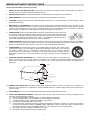
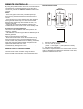
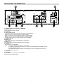
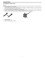
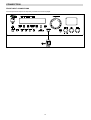
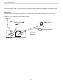
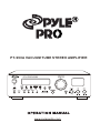
PT-990A VACUUM TUBE STEREO AMPLIFIER
MASTER VOLUME
PT-990A TUBE STEREO AMPLIFIER
POWER ON
·
0
0
BAL ANCE
TREBLE
Ⅱ
Ⅳ
Ⅱ
Ⅷ
Ⅹ
Ⅹ
www.pyleaudio.com
R
0
Ⅵ
Ⅷ
L
Ⅱ
Ⅵ
STEREO
LINE IN
Ⅵ
TUNING
0
Ⅷ
USB
BASS
Ⅱ
PL AYER INPUT
Ⅳ
·
DIGITAL
IN
Ⅳ
SPEAKER
A+B
Ⅳ
SENSOR
SPEAKER
A/B
·
PHONES
Ⅵ
TUNER
Ⅷ
MD
Ⅳ
TAPE
PHONO
Ⅹ
PL AYER INPUT
ST. LINE IN
Ⅹ
AUX 1
AUX 2
· Ⅵ · Ⅴ
CD
DVD
Ⅶ
STEREO
DIRECT
USB
· Ⅸ · Ⅷ
STANDBY
Ⅹ
· Ⅲ · Ⅱ
·
Ⅰ
CONTENTS
SAFETY INFORMATION………………………………………………………………………………………………………………… 1
IMPORTANT SAFETY INSTRUCTIONS………………………………………………………………………………………………. 2
REMOTE CONTROLLER……………………………………………………………………………………………………………….. 3
LOUDSPEAKER POSITIONING……………………………………………………………………………………………………….. 4
FRONT PANEL INFORMATION………………………………………………………………………………………………………… 5
REMOTE CONTROL INFORMATION…………………………………………………………………………………………………. 6
REAR PANEL INFORMATION………………………………………………………………………………………………………….. 7
CONNECTIONS
- LOUDSPEAKER CONNECTIONS……………………………………………………………………………………………………. 8
- AUDIO CONNECTIONS………………………………………………………………………………………………………………... 9
- DIGITAL CONNECTIONS……………………………………………………………………………………………………………… 9
- FRONT INPUT CONNECTIONS………………………………………………………………………………………………………. 10
- AERIAL CONNECTIONS……………………………………………………………………………………………………………… 11
BASIC OPERATION……………………………………………………………………………………………………………………… 12
RADIO DATA SYSTEM (OPTIONAL)……………………………………………………………………………………………………14
TROUBLESHOOTING…………………………………………………………………………………………………………………… 15
SPECIFICATIONS………………………………………………………………………………………………………………………… 16
SAFETY INFORMATION
Caution:
To reduce the risk of electric shock, do not remove Cover (or back)
No user-serviceable parts inside.
Refer servicing to qualified service personnel.
Do not expose this appliance to rain or moisture
This lightning flash with arrowhead symbol, within an equilateral
triangle is intended to alert the user to the presence of uninstalled
“dangerous voltage” within the product’s enclosure that may be of
sufficient magnitude to constitute a risk of electric shock to persons.
The exclamation point within an equilateral triangle is intended to alert
the user to the presence of important operating and maintenance
(servicing) instructions in the literature accompanying the appliance.
CLASS 1
LASER PRODUCT
The marking of products using lasers (except for some areas). The
label is attached to the rear panel and says that the component uses
beams that have been classified as Class 1,which means the unit is
utilizing laser beams that are of weaker class. There is no danger of
hazardous radiation outside the unit
ACCESSORIES
1. RCA cord (yellow color).
2. Remote control.
3. Battery AA x 2 for Remote control
4. Instruction Manual
1
IMPORTANT SAFETY INSTRUCTIONS
Caution: Read This Before Operating Your Unit.
1.
READ AND FOLLOW INSTRUCTIONS: All the safety and operation instructions should be read before the product is
operated. Follow all operation instructions within this manual.
2.
RETAIN INSTRUCTIONS: The safety and operation instructions should be retained for future reference.
3.
HEED WARNINGS: Comply with all warnings on the product and in the operation instructions.
4.
CLEANING: Unplug this product from the wall outlet before cleaning. Do not use liquid cleaners or aerosol cleaners. Use a
damp cloth for cleaning.
5.
GROUNDING or POLARIZATION: This product may be equipped with a polarized alternating current line plug (a plug
having one blade wider than the other). This plug will fit into the power outlet only one way. This is a safety feature. If you are
unable to insert the plug fully into the outlet, try reversing the plug. If the plug should still fail to fit, contact your electrician
since it is likely you have an out of sate wall socket. Never force the plug into the socket.
6.
OVERLOADING: Do not overload wall outlets or extension cords as this can result in the risk of
fire or electric shock. Overloaded AC outlets, extension cords, frayed power cables, damaged
or cracked wire insulation, and broken plugs are dangerous. They may result in electric shock
or fire hazard. Periodically examine the power cable - if its appearance indicates damage or
deteriorated receptacles have it replaced by your service technician.
7.
POWER SOURCES: This product should be operated only from the type of power source indicated on the rear panel label. If
you are not sure of the type of power supply to your home, consult your product dealer or local power company. For products
intend to be operated from battery power, or other sources, refer to the operation instructions.
8.
ACCESSORIES: Do not place this product on an unstable surface or support. The product may fall,
causing serious injury to a child or adult as well as serious damage to the product. Any mounting of
the product should follow the manufacture’s instructions and use a mounting accessory
recommended by the manufacturer. A product and cart combination should be moved with care.
Quick stops, excessive force, and uneven surfaces may cause the product and cart combination to
overturn.
9.
OUTDOOR ANTENNA GROUNDING: If an outside antenna or cable system is connected to the
product, be sure the antenna or cable system is grounded so as to provide some protection against voltage surges and
built-up static charges. The example below is for reference only. Correct grounding should always be installed by an
electrician.
AN TEN NA
LEAD IN
WIRE
G ROU ND
CLAMP
ANTENNA
DISCH ARGE UNIT
(NEC SEC TION 810-21)
ELEC TRIC
SERVI CE
EQUIPMEN T
GRO UNDI NG COND UC TORS
(NEC SECTION 810-21)
GRO UND CLAMPS
POWER SERVIC E GRO UN DIN G
ELEC TRODE SYSTEM
(NEC ART 250.PART H)
10. POWER-CORD PROTECTION: The power supply cables should be routed so that they are not likely to be walked on or
pinched by items placed upon or against them, paying particular attention to cables at plugs and the point where they exit
from the product.
11. ATTACHMENTS: Do not use unauthorized attachments as they may cause faults with the unit.
12. CONDITIONS REQUIREING SERVICE: Unplug this product from the wall outlet and refer servicing to qualified service
personnel under the following conditions:
a) If the unit exhibits sudden unusual operation or unusual display characteristics.
b) If the unit exhibits sudden unusual operation or unusual display characteristics.
c) b. If liquid has been spilled, or objects have fallen into the product.
d) If the product has been exposed to rain or water.
e) If the product does not operate normally by following the operation instructions, adjusting only those controls that are
covered by the operation instructions. (NOTE: improper adjustment of other controls may result in damage and will
often require extensive work by a qualified technician to restore the product to its normal operation).
f)
If the product has been dropped or damaged in any way.
g) If the product exhibits a distinct change in performance.
2
IMPORTANT SAFETY INSTRUCTION
13. SERVICING: Do not attempt to service this product yourself as removing cover may expose you to dangerous voltages or
other hazards. Refer all servicing to qualified service personnel.
14. LIGHTNING: For added protection for this product during a thunderstorm, or when it is left unattended and unused for long
period of time, unplug it from the wall outlet and disconnect the antenna or cable system. This will prevent damage to the
product due to lightning and power line surges.
15. REPLACEMENT PARTS: Should replacement parts be required, have the service technician verify that the replacement
parts he uses have the same safety characteristics as the original parts. Use of unauthorized replacements parts can cause
fire or electric shock.
16. SAFETY CHECK: Upon completion of any service or repairs to this product, ask the service technician to perform safety
checks recommended by the manufacturer to determine that the product is in a safe operating condition.
17. HEAT DISPERSION---Leave at least 10 cm of space between the top, back and sides of the unit and the wall or other
components for proper ventilation.
10cm or more
10cm or more
10cm or mo re
1 0c m o r m ore
18. The apparatus shall not be exposed to dripping or splashing and that no objects filled with liquids, such as vases, shall be
placed on the apparatus.
19. NOTES ON USE
Keep the set free from moisture.
water,and dust.
Do not let foreign objects in the set.
Avoid high temperatures
Allow for sufficient heat dispersion
when installed on a rack.
Unplug the power cord when not
using the set for long periods of
time
Handle the power cord carefully.
Hold the plug when unplugging the
cord.
Do not let insecticides,benzene,and
thinner come in contact with the set.
*(For sets with ventilation holes)
Never disassemble or modify the set
in any way.
Do not obstruct the ventilation
holes
3
REMOTE CONTROLLER
BATTERY INSTALLATION
By using the provided remote control unit, the receiver can be
controlled from your listening position. To use the remote
control unit, point it at the REMOTE SENSOR window of the
receiver.
Notes:
- Even if the remote control unit is operated within the
effective range, remote control operation may be impossible if
there are any obstacles between the unit and the remote
control.
- If the remote control unit is operated near other appliance
which generate infrared rays, or if other remote control
devices using infrared rays are used near the unit, it may
operate incorrectly.
- The power is turned on/off (standby) by pressing the
POWER button on the remote control unit in standby mode.
Precautions concerning batteries
-Be sure to insert the batteries with correct positive+ and
negative – polarities.
- Use batteries of the same type. Never use different types of
batteries together.
- Rechargeable and non-rechargeable batteries can be used.
Refer to the precautions on their labels.
- When the remote control unit is not to be used for a long
time (more than a month), remove the batteries from the
remote control unit to prevent them from leaking. If they leak,
wipe away the liquid inside the battery compartment and
replace the batteries with new ones.
- Do not heat or disassemble batteries and never dispose of
old batteries by throwing them in a fire.
1.
2.
Remove the battery compartment cover.
Insert two “AA” dry batteries.
Make sure that the batteries are inserted with their
positive “+” and negative “-” poles positioned correctly.
3. Close the cover until it clicks.
If the distance required between the remote control unit and
main unit decreases, the batteries are exhausted. In this case,
replace the batteries with new one
REMOTE CONTROL OPERATION RANGE
Use the remote control unit within a range of about 7
meters (23 feet) and the angles of up to 30 degrees aiming
at the remote sensor.
4
FRONT PANEL INFORMATION
1
2
3
4
5
6
7
8
10
9
·
0
0
·
Ⅰ
·
Ⅱ
Ⅵ
Ⅷ
Ⅹ
19
20
Ⅹ
18
21
Ⅳ
Ⅵ
·
17
Ⅷ
· Ⅵ · Ⅴ
Ⅳ
Ⅶ
15 16
Ⅷ
Ⅷ
13 14
Ⅱ
Ⅵ
Ⅵ
12
0
Ⅳ
Ⅳ
11
Ⅱ
Ⅹ
0
Ⅹ
Ⅳ
· Ⅸ · Ⅷ
· Ⅲ · Ⅱ
Ⅹ
Ⅱ
22
1. POWER ON/OFF
Push this button to turn the unit into standby mode, push it again to turn off the unit.
2. Stereo Direct
Press this button ,the unit will change to stereo direct output mode, all the signal through this unit will not be amplify.
3. DVD/CD
Press to active the DVD inputs
4. AUX1/AUX2
Press to active the AUX1/AUX2 input on the rear panel.
5. PLAYER INPUT/ST.LINE IN
Press to select the iPod connected to iPod in on the front panel. Press it again the STEREO LINE IN jack will be actived.
6. TAPE/PHONO
Press to select the Cassette Deck source equipment for output through this unit.
7. MD
Press to active the DAB inputs.
8. TUNER
Press to select the built in TUNER. Press it again to select FM or AM tuning
9. LED Indicator
Lights green when the amplifier is turned on. Lights red when the amplifier is in standby mode or in operation.
10. MASTER VOLUME
Rotate this knob clockwise or counterclockwise, the master volume will be increased or decreased.
11. USB PORT
1.1 format USB port,.
12. PHONES
Jack for the stereo headphones.
13. SPEAKER A/B
Press it once, the speaker that connect to Speaker A outputs will work, press it again Speaker B outputs’s speaker will work.
14. SPEAKER A+B
Press this button, the speaker A&B outputs’s speaker will work together.
15. DIGITAL IN
Press this button to active the PCM digital in input .
16 .USB
Press it to active the USB port.
17. TUNING +/Tuner frequency up & down
18. PLAYER INPUT
Jack for iPod .
19. STEREO LINE IN jack
Connect to the stereo output terminal equipment.
20. Balance
Rotate this knob clockwise or counterclockwise for Balance adjustment.
21. Bass
Rotate this knob clockwise or counterclockwise for Bass adjustment.
22. Treble
Rotate this knob clockwise or counterclockwise for Treble adjustment.
5
REMOTE CONTROL INFORMATION
5. Speaker A+B
Press this button, the speaker A&B outputs’s speaker will
work together..
6. Memory
Press it to store the broadcast station as a preset
7. APS
In tuner mode, press this button to allocate and memorize
radio station automatically.
8. PTY Search
No PTY inforamtion would be displayed.
9. ST/Mono
Press this button to alternate between Stereo and Mono mode
when listen to FM broadcast.
10. Station +/Press these buttons to select a preset channel during the
tuner mode.
11.
When insert a MP3 player in the USB port, press this button
to pauses the playback.
12. Auto/Manual
This button is used to select AUTO or MANUAL tuning for AM
and FM stations. Press once to set to AUTO ,again for
MANUAL
When insert a MP3 player in the USB port press this button to
stop the playback.
Tuning13.
When select the built in tuner, press it to tune frequency
down.
When insert a MP3 player in the USB port press this button to
select the previous track
14.
When insert a MP3 player in the USB port press this button to
starts the playback
15. USB
Active the USB port.
16. DVD/CD
Press to active the DVD inputs.
17. MD
Press to active the DAB inputs.
18. TAPE/PHONO
Press to select the Cassette Deck source equipment for
output through this unit.
19. SPEAKER A/B
Press it once, the speaker that connect to Speaker A outputs
will work, press it again Speaker B outputs’s speaker will
work.
20. iPod/STEREO LINE IN
Press to select the iPod connected to iPod in on the front
panel. Press it again the STEREO LINE IN jack will be
actived.
21. BAND
Press the button to select FM or AM.
22. TUNER
Press to select the built in TUNER. Press it again to select
FM or AM tuning.
23. AUX1/AUX2
Press to active the AUX1/AUX2 input on the rear panel,
24. Stereo Direct.
Press this button, the unit will change to stereo direct output
mode, all the signal through this unit will not be amplify.
25.
Tuning+
When insert a MP3 player in the USB port press this button to
select the next track .
26. Volume +/Press these buttons to decrease or increase the volume.
.
1. Mute
Press this button to mute the sound, push again to cancel the
mute function.
2. Standy
Push this button to turn the unit into standby mode, push it
again to turn off the unit.
3. Digital in
Press this button to active the PCM digital in inpu
4. Display
Press this button to display the state of input source.
6
REAR PANEL INFORMATION
1. Antenna: Connection terminal for AM& FM
2. Mains switch
Use to interrupt the mains voltage
3. RS232 port
4. Analog audio In/Out
- TAPE OUT: Connect to the line input terminals on the TAPE DECK
- AUX IN: Connect to the line output of an external player.
-TAPE IN: Connect to the line output terminals on the TAPE DECK.
- DVD IN: Connect to the line output terminals on the DVD player
- MD IN: Connect to the line output terminals on the DAB player
5. PCM DIGITAL IN
Optical in 1,2
PCM Digital audio input to the digital output of CD player.
Coaxial In 1,2
PCM Digital audio input to the digital output of a CD player
6. Speaker B
For connection of loudspeaker
Note: -The speaker impedance must be 4 and 16 Ohm
- For optimal sound quality there must be a proper connection between the speaker terminal
and the amplifier terminal .
-The cable ends must not be frayed to avoid that they come into contact with each other or
the cabinet back panel
7. Speaker A
The other section for connection of loudspeaker.
8. AC CORD
Connect to the AC mains socket.
7
CONNECTION
LOUDSPEAKER CONNECTIONS
Caution:
To avoid damaging the speakers with a sudden high-level signal, be sure to switch the power off before connecting the speakers.
l Check the impedance of your speakers.
Connect speaker with an impedance of 8 ohms or more. The amplifier’s red speaker terminals are the + (positive) terminals
and the black terminals are the – (negative) terminals.
l The + side of the speaker cable is marked to make it distinguishable from the – side of the cable. Connect this marked side
to the red + terminals and the unmarked side is the black terminal.
l Prepare the speaker cords for connection by stripping off approximately 10 mm or less (no more as this could cause a
short-circuit) of the outer insulation. Twist the wires tightly together so that they are not straggly.
1
2
3
1. Unscrew the knob
2. Insert the speaker cable.
3. Tighten the knob and secure the cable.
8
CONNECTION
AUDIO CONNECTIONS
Note: Do not plug in the mains power lead or turn on the unit before all connections have been made.
Connect to source equipment using phono cables (stereo 2RCA-2RCA).
DIGITAL CONNECTIONS
Two types of digital audio connections can be made to this unit, optical and coaxial.
9
CONNECTION
FRONT INPUT CONNECTIONS
The front panel iPod input is for temporary connections to the iPod player.
10
CONNECTIONS
AERIAL CONNECTIONS
FM aerial
Connect an aerial to the FM 75 ohm socket (a simple wire aerial is supplied for temporary use). Extend the lead and move the
aerial around until you get the best reception. For continued use, we strongly recommended using a 75 ohm outdoor FM aerial.
AM loop aerial
Connect each end of the single length antenna to the antenna terminals. Place the antenna as far from the main system as
possible to prevent unwanted noise and to obtain optimum reception. If the AM loop aerial provided does not receive sufficient
reception, it may be necessary to use an outdoor AM aerial.
FM aerial
OR
FM external aerial
AM loop aerial
OR
AM external aerial
FM 75
AM
LOOP
Ground
11
BASIC OPERATION
PHONES jack
For private listening, insert optional (not included)
headphones (1/4-inch plug) into the PHONES jack, and then
the center and surround speaker will be cut automatically.
iPod in jack
The input ports are for iPod player. It can connect a iPod
player directly or connect to a iPod docking.
Balance/Bass/Treble control knob
BALANCE control is used to adjust the level of speaker .
BASS control is used to adjust the level of the low frequency
sound range.
TREBLE control is used to adjust the level of high frequency
sound rang.
USB
USB 1.1 format port, can connect a USB stick or connect a
MP3 music player directly. When connect a MP3 player, you
can use the remote to achieve the follow function: PLAY,
PAUSE, STOP, SKIP, PREVIOUS
Speaker channel selection
IF you want one section speaker work and another section
stop, press SPEAKER A/B button on the front panel or on the
remote control.
If you want two section speakers work together, press
Speaker A+B button on the front panel or on the remote
control
1. Press the Main Power ON/OFF Switch on the rear panel
to ON.
2. Press the Power On button on the front panel to switch on
the unit.
3. Select the desired source by pushing the corresponding
button
- DVD/CD
- AUX/STEREO LINE IN
- iPod
- MD
- TUNER
- TAPE
- USB(1.1 format only)
- Digital in
this button is use to select below inputs as follow
COAX 1
COAX 2
OPT 1 OPT 2
12
BASIC OPERATION
Stereo
FM stereo broadcasts are received in stereo and the “ ”
indicator lights on the display.
Mono
To compensate for weak FM stereo reception, select this
mode. Reception will now be forced monaural, reducing
unwanted noise.
If DISPLAY button is pressed, the details of incoming source
will be displayed.
Preset Tuning
This facility is used to store FM, AM broadcasting from
channel 1 to15 respectively.
How to select preset stations
Press the “STATION buttons” (numbers)on remote control to
select a preset channel during the tuner mode.
Manual Memory Presetting
1. Press the Tuner button on the front panel or on the remote
control, then press the Band button on the remote to select
FM or AM.
2. Press the TUNING + or TUNING - buttons to select a
frequency channel you want to preset.
3. Press the MEMORY button briefly.
4. While the “MEM” indicator is lit, press TUNING+ or
TUNING - button to select a preset station. The station
number will be displayed on the screen.
5. Press the MEMORY button to confirm.
To store more stations, repeat steps 3 to 6.
8
Radio Operations
Automatic Tuning
1. Press the Main Power On/Off switch on the rear panel
first, then press the Power On/Off button on the front
panel to turn this unit on.
2. Press the Tuner button on the front panel or on the
remote control, then press the Band button on the
remote to select FM or AM.
3. Press the “AUTO/MANUAL” button on remote control to
activate automatic selection. (Default mode is Manual
selection) (Note: Auto appears on the display.)
4. Press TUNING + and TUNING - to select the station you
want to listen to. When a station is tuned in, the tuning
process will stop automatically. (Automatic selection)
5. Press TUNING + or TUNING - again to select another
channel.
Manual Tuning
It is for selecting stations, which cannot be tuned
automatically (manual selection)
To tune a channel manually:
Skip step 3 in the above procedures. Each time the
TUNING+ or TUNING- button is pressed momentarily (0.5
second or less), the frequency changes by a fixed step: FM:
50 kHz steps; MW: 10 kHz steps.
Two FM modes available:
Press ST/MONO button on remote control to select Stereo
mode or Mono mode.
13
RADIO DATA SYSTEM (Optional)
RADIO DATA SYSTEM (RDS)
RDS is a method for the transmission of additional
information from local Radio Stations. It can only operated in
FM mode. For example, name of the station broadcasting,
name of the program or the type of program will be shown on
the multi-function display.
d) RT (Radio text)
Press “DISPLAY” on remote control until “RT” appears.
Some Text messages will be shown.
Note: “NO RT” will be shown if the signal from local radio
station is not strong enough or no such service.
It functions only when the local broadcasting stations have
the RDS transmission and the signal is strong enough.
PTY SEARCH (Program Type Search)
Press “DISPLAY” on remote control, there are functions for
PS, PTY, WAIT CT and RT.
1.
Press the “PTY SEARCH ” on remote control, “PTY
SELECT” will flash on the display.
After you have selected the radio program, press “DISPLAY”
on the remote control, and then the information of the
program will be shown on the screen.
2.
Press TUNING + /- to choose the program type, for
example, NEWS, SPORT, …etc.
a) PS (Program Service Name)
3.
Press “PTY SEARCH” again once you choose the
program type.
Press “DISPLAY” on remote control until “PS” appears. The
current station name will be shown.
4. When the type of program tuned in, it will stop searching,
otherwise, “NO FOUND” will appear.
Note: “NO PS” will be shown if the signal from local radio
station is not strong enough or no such service.
APS (Auto Program Search)
b) PTY (Program Type)
1.
Select your FM or AM band.
Press ”DISPLAY” on remote control until “PTY” appears.
The current name type of the program will be shown.
2.
Pressing the “APS” on remote control, it will search the
available stations.
The searched stations will be
memorized in the respective band memory up to
maximum 15 memories.
Note: “NO PTY” will be shown if the signal from local radio
station is not strong enough or no such service.
Note: Weak station may also be storied in memorizes, so
manual memory presetting may be needed in order to have
better receiving.
c) CT (Clock - Time)
Press “DISPLAY” on remote control, then “WAITING CT”
will appear.
The current time from Radio Station will be shown, e.g. 15:30
Note:
1. The Clock - Time will be only transmitted from local radio
station once a minute, so you need to wait for less than 1
minute to show the result.
2. “NO CT” will be shown if the signal from local radio
station is not strong enough or no such service.
14
TROUBLESHOOTING
To determine any problem with your receiver, always check the most obvious possible causes first. If any problem still remains
after your having checked the items below, consult your nearest dealer.
Problem
Probable Cause
Suggestion
Amplifier
When listening to the music in stereo.
Speakers are connected wrong.
After checking, if needed, reconnect.
Left/right speakers reversed.
Low hum or buzz sound
Power cords or lighting placed near this
Place this product as far as possible
product.
from lighting or power leads
Sound is only heard from one channel
One of the input cords is disconnected.
Connect the input leads and
The BALANCE control is set to one side. adjust the BALANCE control.
Sound cuts off when listening to the
Speaker impedance is less than
After turning off the power and then
music or no sound even though power is prescribed for this unit.
turning it on again, reduce the volume or
ON.
change to the correct 8 ohm speakers.
Low bass response.
Speaker polarity (+/-) is reversed.
Check all speakers for correct polarity.
Tuner
An unusual hissing noise is heard when
A slight noise may be heard because the Try reducing the treble sound by turning
listening to the broadcast in stereo, but
method used for modulation of FM
the treble controls.
not heard when listening monaurally.
stereo broadcasts in different than that
used for monaural broadcasts.
Noise is excessive in both stereo and
Poor location and/or direction of the
Set the FM mode to monaural by
monaural broadcasts.
antenna. Transmitted station is too far
pressing the STEREO/MONO button.
away.
(Note that the broadcast will then be
heard as monaural sound)
Sound is distorted and/or the volume
Broadcast signals are poor or poor
If an indoor antenna is being used,
level becomes low.
antenna placement
change to an outdoor antenna
Excessive distortion in speaker output
Poor reception area
Try using an antenna with more
elements.
Remote Control Unit
Remote control not working
The batteries are exhausted.
Replace with new batteries.
The remote control unit is too far from
the receiver or out of the effective range.
15
Operate the Remote Control unit within
the effective range
SPECIFICATIONS
Max Power Output:
A Speaker :
B Speaker:
A+B Speaker
Total Harmonic Distortion:
Inter-modulation distortion:
requency Response:
Signal/Noise ratio:
Signal/Noise ratio:
Channel Separation:
Audio Analogue input
Senstivity/Impedance:
Tuning Range:
THD:
Signal/Noise ratio
Antenna inputs:
General:
Mains voltage:
Dimensions:
Option
USB multimedia player for audio
300W×2CH (RMS,THD=0.25%,8 ohm)(20Hz-20kHz)
4~8 ohm
4~8 ohm
8 ohm
<0.005 (Vin=200mV, 1W Power output)
<0.008
+/- 0.5dB, 20Hz-22kHz
110 dB(Digital In)
110 dB(Analog In)
>70dB
200mV/47 Kohm
FM 87.5 MHz-108MHz,AM 530 kHz-1710 kHz
(FM preset 20 station, AM preset 10 station)
FM-0.7%.AM-1%~1.3%
FM: 68dB,AM: 45dB
FM75 ohms unbalance. AM: Loop Antenna
110V-60Hz
434(W)×317(D)×134(H)mm / 17.09” x 12.48” x 5.28” inches
*Design and specifications are subject to change without notice.
16