1
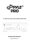
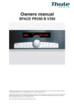
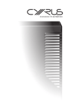
EXEO AMP
CONTENTS
SAFETY INFORMATION
1
IMPORTANT SAFETY INSTRUCTIONS
2
ACCESSORIES
4
CONNECTIONS
5
REMOTE CONTROL INFORMATION
7
FRONT PANEL INFORMATION
9
REAR PANEL INFORMATION
10
OPERATION AND FUNCTIONS
11
TROUBLESHOOTING GUIDE
13
SPECIFICATIONS
14
SAFETY INFORMATION
Caution:
-
To reduce the risk of electric shock, do not remove Cover (or back)
-
No user-serviceable parts inside.
-
Refer servicing to qualified service personnel.
This lightning flash with arrowhead symbol, within an equilateral
triangle is intended to alert the user to the presence of uninstalled
“dangerous voltage” within the product’s enclosure that may be of
sufficient magnitude to constitute a risk of electric shock to persons.
The exclamation point within an equilateral triangle is intended to alert
the user to the presence of important operating and maintenance
(servicing) instructions in the literature accompanying the appliance.
The symbol on this product indicates that it is of CLASS II
(double insulated) construction.
1
IMPORTANT SAFETY INSTRUCTIONS
CAUTION: READ THIS BEFORE OPERATING YOUR UNIT.
1.
READ AND FOLLOW INSTRUCTIONS: All the safety and operation instructions should be read before the product is operated.
Follow all operation instructions within this manual.
2.
RETAIN INSTRUCTIONS: The safety and operation instructions should be retained for future reference.
3.
HEED WARNINGS: Comply with all warnings on the product and in the operation instructions.
4.
CLEANING: Unplug this product from the wall outlet before cleaning. Do not use liquid cleaners or aerosol cleaners. Use a
damp cloth for cleaning.
5.
GROUNDING or POLARIZATION: This product may be equipped with a polarized alternating current line plug (a plug having
one pin wider than the other). This plug will fit into the power outlet only one way. This is a safety feature. If you are unable to
insert the plug fully into the outlet, try reversing the plug. If the plug should still fail to fit, contact your electrician since it is likely
you have an out of safe wall socket. Never force the plug into the socket.
6.
OVERLOADING: Do not overload wall outlets or extension cords as this can result in the risk of
fire or electric shock. Overloaded AC outlets, extension cords, frayed power cables, damaged
or cracked wire insulation, and broken plugs are dangerous. They may result in electric shock
or fire hazard. Periodically examine the power cable - if its appearance indicates damage or
deteriorated receptacles have it replaced by your service technician.
7.
POWER SOURCES: This product should be operated only from the type of power source indicated on the rear panel label. If
you are not sure of the type of power supply to your home, consult your product dealer or local power company. For products
intend to be operated from battery power, or other sources, refer to the operation instructions.
8.
ACCESSORIES: Do not place this product on an unstable surface or support. The product may fall,
causing serious injury to a child or adult as well as serious damage to the product. Any mounting of
the product should follow the manufacture’s instructions and use a mounting accessory
recommended by the manufacturer. A product and cart combination should be moved with care.
Quick stops, excessive force, and uneven surfaces may cause the product and cart combination to
overturn.
9.
OUTDOOR ANTENNA GROUNDING: If an outside antenna or cable system is connected to the product, be sure the antenna
or cable system is grounded so as to provide some protection against voltage surges and built-up static charges. The example
below is for reference only. Correct grounding should always be installed by an electrician.
ANTENNA
LEAD IN
WIRE
GROUND
CL AMP
ANTENNA
DISCHARGE UNIT
(NEC SECTION 810-2 1)
ELECTRIC
SERVICE
EQUIPMENT
GROUNDING CONDUCTORS
(NE C S ECTION 810 -21)
GROUND CL AMPS
POWER SERVICE GROUNDING
ELECTRODE SYSTEM
(NEC ART 2 50.PART H)
10. POWER-CORD PROTECTION: The power supply cables should be routed so that they are not likely to be walked on or pinched
by items placed upon or against them, paying particular attention to cables at plugs and the point where they exit from the
product. The mains plug of the power supply cord shall remain readily operable.
11. ATTACHMENTS: Do not use unauthorized attachments as they may cause faults with the unit.
2
IMPORTANT SAFETY INSTRUCTIONS
12. CONDITIONS REQUIRING SERVICE: Unplug this product from the wall outlet and refer servicing to qualified service personnel
under the following conditions.
a)
If the unit exhibits sudden unusual operation or unusual display characteristics.
b)
If liquid has been spilled, or objects have fallen into the product.
c)
If the product has been exposed to rain or water.
d)
If the product does not operate normally by following the operation instructions, adjusting only those controls that are
covered by the operation instructions. (NOTE: improper adjustment of other controls may result in damage and will often
require extensive work by a qualified technician to restore the product to its normal operation).
e)
If the product has been dropped or damaged in any way.
f)
If the product exhibits a distinct change in performance.
13. SERVICING: Do not attempt to service this product yourself as opening or removing covers may expose you to dangerous
voltage and may damage precision components. Refer all servicing to qualified service personnel.
14. LIGHTNING: For added protection during a lightning storm, or when it is left unattended and unused for long period of time,
unplug it from the wall outlet and disconnect the antenna or cable system. This will prevent damage to the product due to
lightning and power line .
15. REPLACEMENT PARTS: Should replacement parts be required, have the service technician verify that the replacement parts
he uses have the same safety characteristics as the original parts. Use of unauthorized replacements parts can cause fire or
electric shock.
16. SAFETY CHECK: Upon completion of any service or repairs to this product, ask the service technician to perform safety checks
recommended by the manufacturer to determine that the product is in a safe operating condition.
17. HEAT DISPERSAL: Leave at least 10 cm of space between the top, back and sides of the unit and the wall or other electrical
components.
18. The apparatus shall not be exposed to dripping or splashing and that no objects filled with liquids, such as vases, shall be placed
on the apparatus.
19. NOTES ON USE
Keep the set free from moisture.
water,and dust.
Do not let foreign objects in the set.
Avoid high temperatures
Allow for sufficient heat dispersion
when installed on a rack.
Unplug the power cord when not
using the set for long periods of
time
Handle the power cord carefully.
Hold the plug when unplugging the
cord.
Do not let insecticides,benzene,and
thinner come in contact with the set.
* (For sets with ventilation holes)
Do not obstruct the ventilation
holes
Never disassemble or modify the set
in any way.
3
ACCESSORIES
You should find the following accessories included:
1. Mains cord
2. RCA cord
3. Remote control + batteries AAA x 2
4. Operator’s Manual.
1
2
3
4
4
CONNECTIONS
Connection precautions
SUB OUT terminals
When connecting, either disconnect the power plug from
These terminals are used to connect to an active subwoofer.
the power outlet or turn off the unit’s power using the
Use pin-plug cords to connect the terminals to the INPUT
POWER switch (if any).
terminals on the subwoofer.
Check the left and right channels and connect properly
(Left to L and Right to R).
Insert the plugs securely. Improper connection can lead to
generation of noise.
E.g. compact disc player
ACTIVE
SUBWOOFER
(NOT INCLUDED)
Connect the CD terminals to the OUTPUT terminals on the
compact disc player using the pin-plug cord.
Speaker systems
To avoid damaging the speakers with a sudden high-level
signal, be sure to switch the power off before connecting the
OUTPUT
speakers.
Check the impedance of your speakers.
Connect speaker with an impedance of 4 ohms or more.
The amplifier’s red speaker terminals are the + (positive)
terminals and the black terminals are the – (negative)
terminals.
The + side of the speaker cable is marked to make it
distinguishable from the – side of the cable. Connect this
Recording connections Connect the REC OUT terminals to
marked side to the red + terminals and the unmarked side
the input (LINE IN) terminals on the tape deck using the
is the black terminal.
pin-plug cord.
Prepare the speaker cords for connection by stripping off
approximately 10 mm or less (no more as this could cause
a short-circuit) of the outer insulation. Twist the wires
LI NE
( I N) REC
PLAY( OUT)
tightly together so that they are not straggly.
1
A
B
2
3
5
1.
Unscrew the knob
2.
Insert the speaker cable.
3.
Tighten the knob and secure the cable.
CONNECTIONS
PHONO
Connect the turntable’s output cord L (white) plug to the L PHONO terminal and the R (red) plug to the R PHONO terminal.
If your turntable is equipped with a grounding cable, connect it to the unit’s GND terminal. But disconnect it if you notice increased
humming.
AUDI O
AUX1 terminals
This terminal have an electrical performance which is equivalent to that of the CD terminals which means that it can be used as the
audio output terminals for a line level source. Connect this terminal to the OUTPUT terminal on the component using the pin-plug
cord.
AUX2 terminal
This terminal has an increased sensitivity (x4) compared to the other line level inputs.
Headphone terminal
For connection of a pair of headphones.
6
REMOTE CONTROL INFORMATION
By using the provided remote control unit, the receiver can
be controlled from your listening position. To use the remote
control unit, point it at the REMOTE SENSOR window of the
receiver.
REMOTE CONTROL OPERATION RANGE
Use the remote control unit within a range of about 7
meters (23 feet) and the angles of up to 30 degrees aiming
at the remote sensor.
Notes:
BATTERY INSTALLATION
- Even if the remote control unit is operated within the
effective range, remote control operation may be impossible
if there are any obstacles between the unit and the remote
control.
- If the remote control unit is operated near other appliance
which generate infrared rays, or if other remote control
devices using infrared rays are used near the unit, it may
operate incorrectly.
Precautions concerning batteries
-Be sure to insert the batteries with correct positive+ and
negative – polarities.
- Use batteries of the same type. Never use different types of
batteries together.
- Rechargeable and non-rechargeable batteries can be used.
Refer to the precautions on their labels.
- When the remote control unit is not to be used for a long
time (more than a month), remove the batteries from the
remote control unit to prevent them from leaking. If they leak,
1.
Remove the battery compartment cover.
2.
Insert two “AAA” dry batteries.
wipe away the liquid inside the battery compartment and
Make sure that the batteries are inserted with their
replace the batteries with new ones.
-
positive “+” and negative “-” poles positioned correctly.
Do not heat or disassemble batteries and never dispose
of old batteries by throwing them in a fire.
3.
Close the cover until it clicks.
If the distance required between the remote control unit and
main unit decreases, the batteries are exhausted. In this
case, replace the batteries with new one.
7
REMOTE CONTROL INFORMATION
1
2
3
4
6
5
6. Memory
Does not apply.
7. Number Keys
Does not apply.
8. DIM
Press this button to toggle the brightness between: 25%, 50%,
75% & 100%.
9. MODE
Does not apply.
10. Menu
Press the AMP button and then press the Menu button to enter
the menu.
11. Cursor keys◄►▲▼
12. Enter
To confirm selection.
13. Tuning +/Does not apply.
14. Volume+/To increase or decrease the volume.
15. Mute
Press this button to mute the audio, press it again to cancel the
mute function.
16.
Does not apply.
17.
Does not apply.
18.
Does not apply.
19.
Does not apply.
20. CDP
Press this button to activate the CDP input (also switches on
an EXEO CDP from Standby, and switches off any other EXEO
source).
21. NET
Press this button to activate the NET input (also switches on an
EXEO NET from Standby, and switches off any other EXEO
source).
22. DAB
Press this button to activate the DAB input.
23. AUX1
Press this button to active the AUX1 input.
24. AUX2
Press this button to active the AUX2 input.
25. Phono
Press this button to active the PHONO input.
26. AMP
Press this button to activate the EXEO AMP from Standby.
27. Speaker A/B
Press this button to choose between SPEAKER A, SPEAKER
B, SPEAKER A+B and SPEAKER OFF.
7
8
9
10
11
12
13
14
15
16
17
20
21
19
18
23
22
24
25
27
26
1. System Off
Press this key to turn off the EXEO AMP and any other EXEO
product.
2.
Does not apply.
3. Autotune
Does not apply.
4. Info
Does not apply.
5. ST/Mono
Does not apply.
8
FRONT PANEL INFORMATION
5
1
1.
2
3
4
7
Standby/On
Press it to turn on the unit and press it again to turn it off.
2.
LED Indicator
Is OFF when the amplifier is turned on. It is red when the amplifier is in standby mode.
3.
Input
Rotate this knob clockwise or counterclockwise to choose the input source between: CDP, NET, DAB, AUX1, AUX2, PHONO. Press
it to confirm the selection.
Press and hold this button to enter the menu for the below settings: EQ, SPEAKER, LOUDNESS, DISPLAY, HP FILTER, PHONO.
4.
Display
5.
Volume knob
To increase or decrease the volume. Changing volume setting un-mutes the system.
6.
AUX2
3.5mm mini-jack input.
7.
Headphone
6.5mm jack stereo headphone output.
9
REAR PANEL INFORMATION
1
2
3
4
6
7
8
9
1.
PHONO: For connection of a turn table (Note: Additional ground terminal available above inputs)
2.
CDP: For connection of a CD player e.g. EXEO CDP
3.
NET: For connection of a NET tuner e.g. EXEO NET
4.
DAB: For connection of e.g. a DAB tuner
5.
AUX1 : For connection of a line level source
6.
PRE OUT: For connection of e.g. a external power amplifier
7.
REC OUT: For connection of e.g. an external tape deck.
8.
SUB OUT: For connection of e.g. an active subwoofer
9.
SPEAKER OUT: For connection of loudspeakers
Note: The speaker impedance must be 4-8 Ohms. For optimal sound quality there must be a proper connection between the
speaker terminal and the amplifier terminal. The cable ends must not be frayed, to avoid that they come into contact with each
other, or the cabinet back panel.
10. AC MAINS INPUT: For connection of mains voltage. Make sure that the plug is correctly inserted, and that the voltage
corresponds to the text printed on the back panel of the cabinet.
Note: All audio inputs and outputs are analogue.
10
OPERATION AND FUNCTION
ON, Off and Standby
1. Turn on the unit by pressing the Standby/ON button on the front panel or the AMP button on the remote control.
2. If you wish to turn off the unit to avoid any power consumption, you must remove the power cord.
Selecting an Input Source
You can choose an input source by the left hand side knob, and press the knob to select. In addition the remote has dedicated input
selection.
Volume Control
On the right hand side knob the volume can be adjusted. Press it to mute or un-mute the system. Changing volume un-mutes the
system.
Menu Layout
The menu is accessed by pressing and holding the left hand side knob, or by pressing AMP and then MENU on the remote.
Use the arrow keys and the ENTER key of the remote, or the left hand side knob on the front panel to operate the menu.
EQ – Bass Control
The amplifier features a bass control with an adjustment of +/-10dB.
EQ - Treble Control
The amplifier features a treble control with an adjustment of +/-10dB.
EQ - Balance Control
The amplifier features a balance control with of -80dB attenuation for each speaker output.
EQ – Direct Out
When this function is on the Bass, Treble and Balance is bypassed. If Direct Out is set to off again, the EXEO AMP will remember
the Bass, Treble and Balance settings.
Speaker Out
A, B, A+B and Off can be selected. In case Off is selected, it is continuously stated in the display.
Loudness
Loudness bypass any EQ function, as it uses the EQ to generate the loudness curve.
Display - Brightness
Levels of 25-50-75 and 100% can be selected. 75% is default. The DIM button on the remote toggles the levels.
Display – Time Out
Time limits of 5 and 20secs can be selected and off. Time Out means the display switches off, if no actions are taken with the time
limit.
11
OPERATION AND FUNCTION
HP Filter
A highpass filter can be set on and off, to match the system with a active subwoofer. The corner frequency is 80Hz and it has a 12dB
slope.
PHONO
The phono input can be set for MM and MC cartridges, the gain is 40 and 60dB respectively.
Factory Reset
The function brings back the unit to default settings.
Firmware
This function shows the firmware version.
12
TROUBLESHOOTING
PROBLEM
CAUSE/REMEDY
No power when the unit is turn on
- Switch on the current at the mains outlet socket
- Check that the plug has been correctly inserted in the socket
- The internal fuse has blown and must be replaced by a qualified service technician
- The power cord has been damaged and must replaced
No Sound
- The unit has not been turned on
- The volume control is set at minimum or muted
- The speaker cables have not been correctly connected
- A wrong input source has been selected
- Input source has been connected
- Speaker setting is set to off
There is sound in one channel only
- The balance control is not correctly adjusted
- The audio input cables have been incorrectly connected or damaged
- The input source is defective
- The speaker cable have been incorrectly connected or damaged
- The speaker is defective
High buzzing
- The audio input cables have been incorrectly connected or damaged
- The ground cable for the record player has not been connected
- The turn table pick-up is defective
Weak bass and poor stereo perspective
- The speaker connection is out of phase. Check that the positive
and negative poles have been correctly connected, both at the back of
the amplifier and at the back of the speaker
Distortion of sound
- Bass and treble control are too high in relation to speaker specifications
- The volume is set too high
The display does not display any
- The amplifier is defective and should be serviced by a qualified technician
information
- Time out for the display is chosen in the menu
The unit does not switch between inputs
- The amplifier is defective and should be serviced by a qualified technician
“ERROR” is displayed on the display
- The amplifier is defective and should be serviced by a qualified technician
13
SPECIFICATIONS
Parameter
Value
Note
Power
Standby Power Consumption
Power Supply Rating
0.73Wrms
300Wrms
Audio - Connectors
Line Level Inputs Connectors
3.5mm Line Level Inputs Connector
Line Level Outputs Connectors
1/4 Headphone Output Connectors
Binding Post
RCA (Phono), gold plated
3.5mm mini-jack, tin-plated
RCA (Phono), gold plated
1/4" (6.2mm) jack, tin-plated
Banana plug & stripped wire
Case = Gnd, Tip = Signal (CDP, NET, DAB, AUX1)
Case = Gnd, Ring = R, Tip = L (AUX2)
Case = Gnd, Tip = Signal (PRE, REC, SUB)
Case = Gnd, Ring = R, Tip = L (HEADPHONE)
Positive terminal = red, Negetive terminal = black
Audio - Line levels
Input maximum swing
Output max swing
Frequency Response L/R - Pre Out
Frequency Response L/R - Rec Out
Signal-to-Noise Ratio - Pre Out
Signal-to-Noise Ratio - Rec Out
Dynamic Range - Pre Out
Dynamic Range - Rec Out
Distortion THD+N - Pre Out
Distortion THD - Pre Out
Distortion THD+N - Rec Out
Distortion THD - Rec Out
Crosstalk - Pre Out
Crosstalk - Rec Out
4.2Vrms
9.5Vrms
+/- 0.05dB
+/- 0.05dB
105dBA
118dBA
104dBA
117dBA
-90dB
-91dB
-101dB
-104dB
-69dB
-95dB
20-20KHz
20-20KHz
0V input, A-wgt
0V input, A-wgt
-60dB, 1KHz, A-wgt
-60dB, 1KHz, A-wgt
1KHz, AES-17, A-wgt, 2Vrms, volume=0dB
1KHz, AES-17, A-wgt, 2Vrms, volume=0dB
1KHz, AES-17, A-wgt, 2Vrms
1KHz, AES-17, A-wgt, 2Vrms
125-16KHz, AES-17, A-wgt
125-16KHz, AES-17, A-wgt
Audio - Phono
MM Gain
MC Gain
Frequency Response L/R - Rec Out
Signal-to-Noise Ratio - Rec Out
Dynamic Range - Rec Out
Distortion THD+N - Rec Out
Distortion THD - Rec Out
Crosstalk - Rec Out
40dB
60dB
+/- 1dB
90dBA / 70dB
90dBA / 60dB
-90dB / -70dB
-100dB / -80dB
-75dB
(i.e. max. input swing = 42mVrms)
(i.e. max. input swing = 4.2mVrms)
20-20KHz (inverse RIAA curve used)
0V input, A-wgt, [MM / MC]
-60dB, 1KHz, A-wgt [MM / MC]
1KHz, AES-17, A-wgt, 2Vrms
1KHz, AES-17, A-wgt, 2Vrms
125-16KHz, A-wgt
Audio - Amplifier
Po@8R
Po@4R
Frequency Response L/R @8R
Frequency Response L/R @4R
Signal-to-Noise Ratio
Dynamic Range
Distortion THD+N
Distortion THD
Crosstalk
>60W
>100W
+/- 1dB
+/- 1dB
101dBA
100dBA
-85dB
-85dB
-70dB
1% THD, incl. 20KHz passive lowpass filter
1% THD, incl. 20KHz passive lowpass filter
20-20KHz, Fo max. 33KHz
20-20KHz, Fo max. 27KHz
0V input, A-wgt
-60dB, 1KHz, A-wgt
1KHz, AES-17, A-wgt, 1/8 rated power
1KHz, AES-17, A-wgt, 1/8 rated power
1KHz, AES-17, A-wgt, 1/8 rated power
14