1
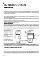
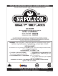
INST
ALLER: THESE INSTRUCTIONS MUST BE CONVEYED TO AND REMAIN WITH THE HOMEOWNER.
INSTALLER:
CERTIFIED UNDER CANADIAN AND AMERICAN NATIONAL STANDARDS,
CAN 1-2.1-M86, AND ANSI Z21.50-1996 RESPECTIVELY FOR GAS-FIRED VENTED ROOM HEATER AND VENTED DECORATIVE GAS APPLIANCE
GAS STOVE
INST
ALLA
TION AND OPERA
TION INSTRUCTIONS FOR
INSTALLA
ALLATION
OPERATION
GAS-FIRED STOVE
NATURAL GAS MODEL
PROPANE GAS MODEL
GS3500 - N
GS3500 - P
CERTIFIED FOR CANADA AND UNITED STATES USING ANSI / AGA / CGA METHODS
WARNING: Improper installation, adjustment, alteration, service or maintenance can
cause injury or property damage. Refer to this manual. For assistance or additional
information consult a qualified installer, service agency or the gas supplier.
FOR YOUR SAFETY
Do not store or use gasoline or other flammable vapours and liquids in the vicinity of
this or any other appliance.
WHAT
TO
WHA
TT
O DO IF YOU SMELL GAS:
•
•
•
•
Turn off main gas supply.
Open windows.
Do not try to light any appliance.
Do not touch any electrical switch; Do not use
any phone in your building.
• Extinguish any open flame.
• Immediately call your gas supplier from a
neighbour's phone. Follow the gas supplier's
instructions.
• If you cannot reach your gas supplier, call the
fire department.
Wolf Steel Ltd., RR#1, 9 NAPOLEON RD.,
Barrie, ON., Canada L4M 4Y8 (705)721-1212
ISO 9002 CERTIFIED
Fax: (705)722-6031 Email: [email protected]
Web: WWW.NAPOLEON.ON.CA
Registered Quality
R-2000
System RR
WORLD RECOGNITION FOR QUALITY
WS-415-55 / 11.10.97
2
PLEASE RETAIN THIS MANUAL FOR FUTURE REFERENCE
TABLE of CONTENTS
PG
2-4
5-6
6
7
INTRODUCTION
Warranty
General Instructions
General Information
Care of Glass, Enamelled & Plated Parts
PG 8
GAS INST
ALLA
TION
INSTALLA
ALLATION
ALLA
TION
INSTALLA
ALLATION
OPTIONAL BLOWER INST
Ornamental Trivet
Log Placement / Charcoal Embers
9-10
OPERA
TION / MAINTENANCE
OPERATION
11
ADJUSTMENTS
VENTING
Location
Chimney Installation
Installing "B" Vent
Adding Vent Sections
Flashing & Storm Collar Installation
Combustion Air
FINISHING
Spill Switch
Venting Action Check
Operating Instructions
Maintenance
Pilot Burner Adjustment
Venturi Adjustment
11-12 REPLACEMENTS
Ordering Replacement Parts
Replacement Parts
Accessories
13-14 TROUBLE SHOOTING GUIDE
PURGE ALL GAS LINES WITH THE GLASS DOOR OF THE STOVE REMOVED. ASSURE THA
THATT A CONTINUOUS GAS FLOW IS A
ATT
THE BURNER BEFORE INST
ALLING THE DOOR.
INSTALLING
UNDER EXTREME VENT CONFIGURA
TIONS, ALLOW SEVERAL MINUTES (5-15) FOR THE FLAME TO ST
ABILIZE AFTER IGNITION.
STABILIZE
CONFIGURATIONS,
WARNING
• Do not burn wood or other materials in this stove.
• Adults and especially children should be alerted to the hazards of high surface temperatures and should stay away to
avoid burns or clothing ignition. Supervise young children when they are in the same room as the stove.
• Due to high temperatures, the stove should be located out of traffic and away from furniture and draperies.
• Clothing or other flammable material should not be placed on or near the stove.
• Any safety screen or guard removed for servicing must be replaced prior to operating the stove.
• It is imperative that the control compartments, burners and circulating blower and its passageway in the stove and venting
system are kept clean. The stove and its venting system should be inspected before use and at least annually by a qualified
service person. More frequent cleaning may be required due to excessive lint from carpeting, bedding material, etc. The
stove area must be kept clear and free from combustible materials, gasoline and other flammable vapours and liquids.
• Under no circumstances should this stove be modified.
• This stove must not be connected to a chimney flue pipe serving a separate solid fuel burning appliance.
• Do not use this stove if any part has been under water. Immediately call a qualified service technician to inspect the stove
and to replace any part of the control system and any gas control which has been under water.
• Do not operate the stove with the glass door removed, cracked or broken. Replacement of the glass should be done by a
licensed or qualified service person.
• Do not strike or slam shut the stove glass door.
WS-415-55 / 11.10.97
3
NAPOLEON gas fireplaces are manufactured under the strict Standard of the world recognized
ISO9002 Quality Assurance Certificate.
NAPOLEON products are designed with superior components and materials, assembled by trained craftsmen who
take great pride in their work. The burner and valve assembly are leak and test-fired at a quality test station. The
complete fireplace is thoroughly inspected by a qualified technician before packaging to ensure that you, the customer, receives the quality product that you expect from NAPOLEON.
NAPOLEON GAS FIREPLACE PRESIDENT'S LIFETIME LIMITED WARRANTY
The following materials and workmanship in your new NAPOLEON gas fireplace are warranted against defects for as long as you own the fireplace. This covers: combustion chamber,
heat exchanger, stainless steel burner, phazer™ logs and embers, ceramic glass (thermal breakage only), gold plated parts against tarnishing, porcelainized enamelled components and aluminum extrusion trims.
Electrical (110V and millivolt) components and wearable parts such as blowers, gas valves,
thermal switch, switches, wiring, remote controls, ignitor, gasketing, and pilot assembly are
covered and NAPOLEON will provide replacement parts free of charge during the first year
of the limited warranty.
Labour related to warranty repair is covered free of charge during the first year. Repair
work, however, requires the prior approval of an authorized company official. Labour costs to
the account of NAPOLEON are based on a predetermined rate schedule and any repair work
must be done through an authorized NAPOLEON dealer.
All specifications and designs are subject to change without prior notice due to on-going product improvements. Napoleon® is a registered trademark of wolf steel ltd. Patents
u.s. 5.303.693.801 - can. 2.073.411, 2.082.915. © wolf steel ltd.
CONDITIONS AND LIMIT
ATIONS
LIMITA
NAPOLEON warrants its products against manufacturing defects to the original purchaser only -- i.e., the individual or legal entity (registered customer) whose name appears on the
warranty registration card filed with NAPOLEON -- provided that the purchase was made through an authorized NAPOLEON dealer and is subject to the following conditions and
limitations:
This factory warranty is nontransferable and may not be extended whatsoever by any of our representatives.
The gas fireplace must be installed by a licenced, authorized service technician or contractor. Installation must be done in accordance with the installation instructions included with
the product and all local and national building and fire codes.
This limited warranty does not cover damages caused by misuse, lack of maintenance, accident, alterations, abuse or neglect and parts installed from other manufacturers will nullify
this warranty.
This limited warranty further does not cover any scratches, dents, corrosion or discolouring caused by excessive heat, abrasive and chemical cleaners nor chipping on porcelain enamel
parts, mechanical breakage of PHAZER™ logs and embers, nor any venting components used in the installation of the fireplace.
NAPOLEON warrants its stainless steel burners against defects in workmanship and material for life, subject to the following conditions: During the first 10 years NAPOLEON will
replace or repair the defective parts at our option free of charge. From 10 years to life, NAPOLEON will provide replacement burners at 50% of the current retail price.
In the first year only, this warranty extends to the repair or replacement of warranted parts which are defective in material or workmanship provided that the product has been operated
in accordance with the operation instructions and under normal conditions.
After the first year, with respect to this President's Limited Lifetime Warranty, NAPOLEON may, at its discretion, fully discharge all obligations with respect to this warranty by refunding
to the original warranted purchaser the wholesale price of any warranted but defective part(s).
After the first year, NAPOLEON will not be responsible for installation, labour or any other costs or expenses related to the reinstallation of a warranted part, and such expenses are
not covered by this warranty.
Notwithstanding any provisions contained in this President's Limited Lifetime Warranty, NAPOLEON’S responsibility under this warranty is defined as above and it shall not in any
event extend to any incidental, consequential or indirect damages.
This warranty defines the obligations and liability of NAPOLEON with respect to the NAPOLEON gas fireplace and any other warranties expressed or implied with respect to this
product, its components or accessories are excluded.
NAPOLEON neither assumes, nor authorizes any third party to assume, on its behalf, any other liabilities with respect to the sale of this product. NAPOLEON will not be responsible
for: over-firing, downdrafts, spillage caused by environmental conditions such as rooftops, buildings, nearby trees, hills, mountains, inadequate vents or ventilation, excessive venting
configurations, insufficient makeup air, or negative air pressures which may or may not be caused by mechanical systems such as exhaust fans, furnaces, clothes dryers, etc.
Any damages to fireplace, combustion chamber, heat exchanger, brass trim or other component due to water, weather damage, long periods of dampness, condensation, damaging
chemicals or cleaners will not be the responsibility of NAPOLEON.
The bill of sale or copy will be required together with a serial number and a model number when making any warranty claims from your authorized dealer. The warranty registration
card must be returned within fourteen days to register the warranty.
NAPOLEON reserves the right to have its representative inspect any product or part thereof prior to honouring any warranty claim.
WS-415-55 / 11.10.97
4
INTRODUCTION
GENERAL INSTRUCTIONS
THIS GAS STOVE SHOULD BE INSTALLED AND SERVICED BY A QUALIFIED INSTALLER to conform with local codes.
In absence of local codes, install to the current CAN1-B149 Installation Code in Canada or to the National Fuel Gas Code, ANSI
Z223.1-1988, and NFPA 54-1988 in the United States.
The stove and its individual shutoff valve must be disconnected from the gas supply piping system during any pressure testing
of that system at test pressures in excess of 1/2 psig (3.5 kPa). The stove must be isolated from the gas supply piping system
by closing its individual manual shutoff valve during any pressure testing of the gas supply piping system at test pressures
equal to or less than 1/2 psig (3.5 kPa).
A 1/8 inch NPT plug, accessible for test gauge connection, must be installed immediately upstream of the gas supply connection to the stove.
This stove must be connected to either a 4" 'B' vent system or any accepted lined chimney system using a liner and vent
connector listed to ULC-S635M (in Canada) or UL-1777 (in USA). The venting connection must be in compliance with the vent
manufacturers installation instructions.
The stove, when installed with a blower, must be electrically connected and grounded in accordance with local codes. In the
absence of local codes, use the current CSA C22.1 CANADIAN ELECTRICAL CODE in Canada or the ANSI/NFPA 70-1990
NATIONAL ELECTRICAL CODE in the United States. The blower power cord must be connected into a properly grounded
receptacle. The grounding prong must not be removed from the cord plug.
Provide adequate ventilation and combustion air. Provide adequate accessibility clearance for servicing and operating the
stove. Never obstruct the front opening of the stove.
GENERAL INFORMA
TION
INFORMATION
FOR YOUR SATISFACTION, THIS STOVE HAS BEEN TEST-FIRED TO ASSURE ITS OPERATION AND QUALITY!
Maximum input is 30,000 BTU/hr for natural gas and 24,000 BTU/hr for propane. When the fireplace is installed at elevations
above 4,500ft, and in the absense of specific recommendations from the local authority having jurisdiction, the certified high
altitude input rating shall be reduced at the rate of 4% for each additional 1,000ft. Maximum output for natural gas is 22,500
BTU/hr at an efficiency of 75% with the fan on, 70% with the fan off; and 18,500 BTU/hr for propane at an efficiency of 77% with
the fan on, 72% with the fan off. The efficiency rating of the fireplace is a product thermal efficiency rating, determined independently of any installed system under continuous conditions and
applies to Canada only.
Where the stove has been factory equipped for hi-altitude using natural gas, the input has
been downrated by 10%. Hi-altitude downrating for propane is
not necessary.
Minimum inlet gas supply pressure is 4.5 inches water column
for natural gas and 11 inches
water column for propane. Maximum inlet gas pressure is 7
inches water column for natural
gas and 13 inches water column
for propane. Manifold pressure
under flow conditions is 3.5
inches water column for natural gas and 10 inches water column for propane.
NO EXTERNAL ELECTRICITY (110 VOLTS OR 24 VOLTS) IS REQUIRED FOR THE GAS SYSTEM OPERATION. Change
in flame appearance from "HI" to "LO" is more evident in natural gas than in propane. Models GS 3500N and GS 3500P are
certified for bedroom and bed-sitting room installations. Expansion / contraction noises during heating up and cooling down
cycles are normal and to be expected.
CARE OF GLASS, PLA
TED AND ENAMELLED P
AR
TS
PLATED
PAR
ARTS
Do not use abrasive cleaners to clean these parts. Buff lightly with a clean dry cloth. Porcelain enamelled components must
be handled with care. The baked-on finish is glass-like. If struck, it will chip! Touch-up paint is available through your Napoleon
dealer.
The glass is 3/16" ceramic glass available from your Napoleon / Wolf Steel Ltd. dealer. DO NOT SUBSTITUTE MATERIALS.
Clean the glass after the first 10 hours of operation with a recommended glass cleaner specifically formulated for gas fireplaces or a non-abrasive, ammonia or vinegar-based glass cleaner. Thereafter clean as required. DO NOT CLEAN GLASS
WHEN HOT! If the glass is not kept clean permanent discolouration and / or blemishes may result.
WS-415-55 / 11.10.97
5
VENTING
LOCA
TION
LOCATION
The most desirable and benefical location for a Napoleon Stove is in the centre of a building, thereby allowing the most efficient
use of the heat created. The location of windows, doors and the traffic flow in the room where the stove is to be located should
be considered. If possible, you should choose a location where the chimney will pass through the house without cutting a floor
or roof joist.
MAINTAIN THESE MINIMUM CLEARANCES TO COMBUSTIBLES:
A.
8"
B.
5"
C. 1"
D.
1" 'B' vent or 6" single
wall vent connector
E.
7"
F.
11"
minimum 18" from stove top to ceiling
NO ADDITIONAL FLOOR PROTECTION IS REQUIRED.
CHIMNEY INST
ALLA
TION THREE TYPES OF CHIMNEY SYSTEMS MAY BE USED WITH THIS STOVE:
INSTALLA
ALLATION
FIGURE 1
A CHIMNEY VENTING THIS STOVE SHALL NOT VENT ANY SOLID FUEL BURNING APPLIANCE.
ALL HORIZONT
AL RUNS MUST HA
VE A 1/4 INCH RISE PER FOOT
HORIZONTAL
HAVE
FOOT..
INSTALLING 'B' VENT:
1.Move the stove into position. Try to center the exhaust of the stove,
midway between two joist to prevent having to cut them. Use a plumb
bob to line up the center.
2. Cut and frame an opening in the roof to provide a 1"
clearance between the outside of the 'B' vent and
any combustible material. DO NOT FILL THIS
SPACE WITH ANY TYPE OF MATERIAL. Nail headers between the joist for extra support. Firestop spacFIGURE 2
ers must be placed on the bottom of each framed
opening in any floor or on top of any framed opening
in any attic that the 'B' vent passes through. FIGURE 2.
3. Hold a plumb bob from the underside of the roof to
determine where the opening in the roof should be.
Cut and frame the roof opening to maintain proper 1"
clearances. FIGURE 3
FIGURE 3
For aesthetics, a 6" telescoping stove pipe may be
installed over the 4" vent connection or 'B' vent. Either use a Napoleon stove pipe adapter available from your Napoleon dealer
or cut approximately 2" from the crimped end of the 6" diameter chimney section to be inserted into the 6-1/4" canopy opening.
WS-415-55 / 11.10.97
6
ADDING VENT SECTIONS:
Add vent sections, twist locking (clockwise) securely, to the required height. The vent should extend, at least, 3 feet above its
point of contact with the roof and, at least, 2 feet higher than any wall, roof or building within 10 feet. FIGURE 4. (This is a guide
line only; local venting codes should be followed which may differ in height and clearance
requirements.)
INST
ALLING FLASHING AND STORM COLLAR
INSTALLING
Remove nails from the shingles above and to the sides of the chimney. Place the flashing
over the vent pipe and slide it underneath the sides
and upper edge of the shingles. Ensure that the vent
pipe is properly centered within the flashing, giving a
3/4" margin all around. Fasten to the roof on the top
and sides. DO NOT NAIL through the lower portion
of the flashing. Make weather-tight by sealing with
caulking. Where possible, cover the sides and top
edges of the flashing with roofing material.
Apply waterproof caulking around the vent, 1" above
the top of the flashing and push the storm collar down
into the caulking. FIGURE 5. Attach a rain cap to the
top of the last vent section.
FIGURE 4
FIGURE 5
COMBUSTION AIR
ANY STOVE NEEDS AIR FOR SAFE OPERATION AND MUST BE INSTALLED IN
SUCH A WAY THAT ADEQUATE COMBUSTION AIR IS AVAILABLE. THIS UNIT IS
DESIGNED TO FUNCTION USING EITHER OUTSIDE OR INSIDE (ROOM) AIR.
If using outside air, connections can be made either through a hole in the wall to line up with the hole
in the pedestal back or through a hole in the floor to line up with the hole in the pedestal base. Use
a fresh air kit available through your Napoleon Firplace dealer or Wolf Steel Ltd. Secure the 4"
diameter aluminium liner in either the back or base of the pedestal. If the air intake is through the
floor, the hole in the pedestal back should be covered. Avoid cutting away floor joist, electrical wiring
or plumbing. Seal around the outside pipe with insulation to prevent drafts. FIGURE 6.
FIGURE 6
GAS INSTALLATION
Bring the gas line to the stove through either a hole in the pedestal back or in the
floor area directly beneath the pedestal base. Install rigid black pipe, a flex connector if local codes permit, or 1/2" type L copper tubing with a 3/8" to 1/2" adapter and
FIGURE 7
a shut-off valve to the stove. FIGURE 7. Seal and tighten securely. The adapter will
be required between the gas valve and the copper tubing or flex connector.
DO NOT KINK CONNECTOR. Check for gas leaks by brushing on a soap and water solution. DO NOT USE OPEN
FLAME.
Alternate locations for the on-off switch are shown in FIGURE 8. For ease of accessibility, an optional remote wall switch or
millivolt thermostat may be installed in a convenient location. Route single strand millivolt wire through the electrical hole
located at the left rear side of the pedestal. The recommended maximum lead length depends on the wire size:
WIRE SIZE
MAX. LENGTH
14gauge
100 feet
16gauge
60 feet
18gauge
40 feet
Attach the two leads to terminals 1 and 3 located on the gas valve
DO NOT CONNECT EITHER THE W
ALL SWITCH, THERWALL
MOST
AT OR GAS V
AL
VE TO ELECTRICITY (110 VOL
TS)
MOSTA
VAL
ALVE
VOLTS)
O
LO
ON
FF
P L T
IH
O I
PI L OT
FIGURE 8
WS-415-55 / 11.10.97
7
OPTIONAL BLOWER SYSTEM
gro
un
bla d
ck
INSTALLATION TO BE DONE BY A QUALIFIED INSTALLER and must be electrically connected and grounded in accordance with local codes. In the absence of local codes, use the current CSA C22.1 CANADIAN ELECTRICAL CODE in Canada or
the ANSI/NFPA 70-1990 NATIONAL ELECTRICAL CODE in the United States.
1. Turn off the gas supply to the fireplace, if
necessary. Mount the variable speed switch: insert the rheostat stem through the 3/8" diameter
hole in the pedestal and from the front secure
with the pal nut. Add the knob.
2. Reaching in from the back of the unit, locate
the bracket holding the heat sensor as shown to
the weld stud and secure using one of the #6
nuts.
3. Attach the bare end of wire (A) to the black
wire of the speed switch using a nut connector.
Attach the flag connector at the other end to one
of the prongs of the heat sensor.
4. Insert the universal bushing into the 7/8" diameter hole in the back of the pedestal.
5. Thread the leads of the power cord through
the slot located at the bottom left of the stove
back panel. Attach the terminal of the ground wire
FIGURE 9
(green) to the threaded weld stud and secure
with a nut.
6. Connect one bare lead of wire (B) to the white wire of the speed switch
using a nut connector. Connect the other end to the bare lead wire of the blower
cord using a nut connector.
7. Attach the other terminal of
ite
the wire (already attached to the
wh
blower) to the heat sensor. One
end must be pushed through the
FIGURE 11
bushing in order to connect to the
blower prong.
8. Mount the cord terminal to
the other blower prong.
9. Using the holes shown, atFIGURE 10
tach the blower to the back stove panel.
10. Bring out any slack in the blower cord. Place the cord into the split
strain relief bushing, just at the point where the cord enters the slot. Clamp the two pieces together and insert the bushing
securely into the slot.
Leak test using a soap and water solution, if the gas supply was disconnected at the valve. Because the blower is thermally
activated, when turned on, it will automatically start approximately 15-30 minutes after lighting the fireplace and will run for
approximately 30-45 minutes after the fireplace has been turned off. Use of the fan increases the output of heat.
WS-415-55 / 11.10.97
8
FINISHING
ORNAMENT
AL TRIVET
ORNAMENTAL
Insert the trivet into the space on the stove top. FIGURE 12
FIGURE 12
CENTER
LOG
LEFT
LOG
RIGHT
LOG
BACK LOG
POSITIONING THE
LOGS IMPROPERLY WILL CAUSE
FLAME IMPINGEMENT AND
SKEWERING
CARBONING.
SCREW
FRONT LOG
CHARCOAL EMBERS
FIGURE 13
LOG PLACEMENT INSTRUCTIONS / CHARCOAL EMBERS
PHAZERTM logs and charcoal embers, exclusive to Napoleon Fireplaces, provide a unique and realistic glowing effect that is
different in every installation. Take the time to carefully position the charcoal embers for a maximum glowing effect.
1. Place the front log onto the main burner, placing it 1/4" - 3/8" away from the burner ports to avoid blocking/covering them.
The left and right spacing between the log ends and the burner ports should be equal. Press down onto the skewering screws.
YOU MAY FIND IT EASIER TO PLACE SOME CHARCOAL EMBERS BENEATH THE FRONT LOG NOW.
2. Place the back log onto the log support brackets located on the rear wall of the combustion chamber. The notch situated
at the lower left of the back log should be centered evenly above the pilot assembly. FIGURE 13.
3. While supporting the back log, to prevent it from falling forward, set the three smaller logs into the pockets and grooves
of the front and back logs, respectively.
Log colours may vary. During the initial use of the fireplace, the colours will become more uniform as colour pigments burn in
during the heat activated curing process.
CHARCOAL EMBERS: Randomly place the embers beneath the front log,
covering all of the burner area beneath the hollowed out section of the
log. FIGURE 14. Place the remaining embers along the front. Keep
ember dust away from burner ports to avoid plugging them.
Fine dust found in bottom of bag not to be used. PHAZERTM logs
and charcoal embers glow when exposed to direct flame. Use only
certified PHAZERTM logs and charcoal embers available from your
Napoleon / Wolf Steel Ltd. dealer.
WS-415-55 / 11.10.97
FIGURE 14
9
OPERATION/MAINTENANCE
SPILL SWITCH
This is a thermally activated switch, attached to the back of the dilution draft hood, which senses the change in temperature
and shuts down the gas valve in the event of a severe downdraft of air or a blocked or disconnected vent. It acts as a safety
shut-off to prevent a build up of carbon monoxide or an explosion of unburnt gases during start up. If the flue is blocked or has
no "draw", the spill switch will automatically shut off the supply of gas within about 5-10 minutes.
TAMPERING WITH THE SWITCH CAN RESULT IN CARBON MONOXIDE (CO) POISONING AND POSSIBLE DEATH.
PURGE ALL GAS LINES WITH THE GLASS DOOR OF THE STOVE REMOVED. ASSURE THAT A CONTINUOUS GAS FLOW IS
AT THE BURNER BEFORE INSTALLING THE DOOR. ALLOW SEVERAL MINUTES (5-15) FOR THE FLAME TO STABILIZE
AFTER IGNITION.
VENTING ACTION CHECK: A CHECK FOR CORRECT VENTING ACTION MUST
BE MADE BEFORE THE INSTALLED STOVE IS LEFT WITH THE CUSTOMER.
Test in the following manner:
1. Close all doors and windows in the room / start exhaust fans in the home /
turn fireplace blower off (if equipped).
2. Set controls to "high" and light the unit.
3. Wait 5 minutes. Light a match and hold it along the edge of the dilution hood
visible through the rear wall opening and extend it 1" into the dilution hood.
4. Venting action is satisfactory if smoke is drawn into the draft dilution hood and
the flame rises vertically and slightly to the right. Venting action is unsatisfactory if the
smoke spills back, and the flame splays horizontally and back towards you.
5. If venting action is unsatisfactory, turn the unit off, wait 10 minutes and try
again. If the smoke or flame is still not drawn into the draft dilution hood, turn the unit
off and check for vent blockage or restriction. If necessary, consult with a qualified inspector.
FIGURE 15
OPERA
TING INSTRUCTIONS
OPERATING
The on-off switch is located on the back of the unit at the top left corner.
When lit for the first time, the fireplace will emit a slight odour for a few
hours. This is a normal temporary condition caused by the curing of the
logs and the "burn-in" of internal paints and lubricants used in the manufacturing process and will not occur again. Simply open a window to sufficiently ventilate the room. After extended periods of non-operation such
as following a vacation or a warm weather season, the fireplace may emit
a slight odour for a few hours. This is caused by dust particles in the heat
exchanger burning off. Open a window to sufficiently ventilate the room.
ON
P
FF
LO
O I
LT
I
H
O
FIGURE 16
WS-415-55 / 11.10.97
10
FOR YOUR SAFETY READ BEFORE OPERATING
A. This fireplace is equipped with a pilot which must be lit by hand while following these instructions exactly.
B. Before operating smell all around the fireplace area for gas and next to the floor because some gas is heavier than air and
will settle on the floor.
• Do not touch any electric switch; do not use any phone in your building.
WHAT TO DO IF YOU SMELL GAS:
• Immediately call your gas supplier from a neighbour's phone.
• Turn off all gas to the fireplace.
Follow the gas supplier's instructions.
• Open windows.
• If you cannot reach your gas supplier, call the fire department.
• Do not try to light any appliance.
C. Use only your hand to turn the gas control knob. Never use tools. If the knob will not turn by hand, do not try to repair it. Call
a qualified service technician. Force or attempted repair may result in a fire or explosion.
D. Do not use this fireplace if any part has been under water. Immediately call a qualified service technician to inspect the
fireplace and replace any part of the control system and any gas control which has been under water.
LIGHTING INSTRUCTIONS: WARNING The gas valve has an interlock device which will not allow the pilot burner to be lit
until the thermocouple has cooled. Allow approximately 60 seconds for the thermocouple to cool.
5.Turn gas knob counter-clockwise
to pilot.
When lighting and re-lighting, the gas knob cannot be
6.Depress slightly and hold gas knob while lighting the pilot with
turned from pilot to off unless the knob is depressed
the push button ignitor. Keep knob depressed for one minute,
slightly.
PL T
then release. If pilot does not continue to burn, repeat steps 3
1.Stop! Read the above safety information
PIEZO
IGNITOR
through 5.
on this label.
FLAME
ADJUSTMENT
KNOB
7.With pilot lit, depress and turn gas knob
2.Turn off all electric power to the fireplace.
to on.
PILOT VARIABLE
to off. GAS KNOB counter-clockwise
3.Turn the gas knob clockwise
ON/OFF SPEED
KNOB SWITCH
8.If equipped with remote on-off switch/ther4.Wait five (5) minutes to clear out any gas. If you smell
mostat, main burner may not come on when you turn valve to
gas including near the floor. Stop! Follow "B" in the
on. Remote switch must be in the on position to ignite burner.
above safety information on this label. If you don't
9.Turn on all electric power to the fireplace.
smell gas go the next step.
FF
O I
ON
O
L T
N
O
FF
O I
P
O
IH
LO
INSTRUCTIONS TO TURN OFF GAS:
1.Turn off all electrical power to the unit if service is
to be performed.
2.Push in gas control knob slightly and turn clockwise
to off. DO NOT FORCE.
MAINTENANCE INSTRUCTIONS TURN OFF THE GAS AND UNPLUG ELECTRICAL POWER BEFORE SERVICING THE STOVE.
CAUTION: Label all wires prior to disconnection when servicing controls. Wiring errors can cause improper and dangerous
operation. Verify proper operation after servicing. This stove and its venting system should be inspected before use and at
least annually by a qualified service person. The area around the stove must be kept clear and free of combustible materials,
gasoline and other flammable vapours and liquids. The flow of combustion and ventilation air must not be obstructed.
1.In order to properly clean the burner and pilot assembly, remove the logs exposing both assemblies.
2.Keep the control compartment, logs, burner, air shutter opening and the area surrounding the logs clean by vacuuming or
brushing, at least once a year.
3.Check to see that all burner ports are burning. Clean out any of the ports which may not be burning or are not burning
properly.
4.Check to see that the pilot flame is large enough to engulf the thermocouple on one leg and reaches toward the burner on
the other leg.
5.Replace the cleaned logs.
6.Check to see that the main burner ignites completely on all openings when the gas knob for the burner is turned on. A 510 second total light-up period is satisfactory. If ignition takes longer, consult your Napoleon dealer/distributor.
7. After extended periods of non-operation such as following a vacation or a warm weather season, the fireplace may emit
a slight odour for a few hours. This is caused by dust particles in the heat exchanger burning off. Open a window to sufficiently
ventilate the room.
WS-415-55 / 11.10.97
11
ADJUSTMENTS
PILOT BURNER ADJUSTMENT
FIGURE 18
Adjust the pilot screw to provide properly sized flame. Turn
in a clockwise direction to reduce the gas flow.
FIGURE 17 & 18.
LO
THERMOPILE
ON
FF
O
THERMOCOUPLE
P L T
IH
O I
VENTURI ADJUSTMENT
PI L OT
FIGURE 17
PILOT SCREW
To access the venturi, remove the four screws securing the burner to the base;
slide to the left, lift up and out. Natural gas models have air shutters set at 1/16
(.063) inch open. Propane gas models have air shutters set at 5/16 (.313) inch
open. Closing the air shutter will cause a more yellow flame, but can lead to
carboning. Opening the air shutter will cause a more blue flame, but can cause
flame lifting from the the burner ports. The flame may not appear yellow immediately; allow 15 to 30 minutes for the final flame colour to be established.
Air shutter adjustment must only be done by a qualified gas installer!
FLAME MUST ENVELOP
UPPER 3/8" TO 1/2" OF
THERMOCOUPLE &
THERMOPILE
FIGURE 19
REPLACEMENTS
ORDERING REPLACEMENT P
AR
TS
PAR
ARTS
Contact your dealer or the factory for questions concerning prices and policies on replacement parts. Normally all parts can
be ordered through your Napoleon dealer or distributor. When ordering replacement parts always give the following information: 1. MODEL & SERIAL NUMBER OF FIREPLACE
3. PART NUMBER
5. FINISH
2. INSTALLATION DATE OF FIREPLACE
4. DESCRIPTION OF PART
REPLACEMENT P
AR
TS, GS 3500
PAR
ARTS,
PAR
T#
ART
GA-GI-135.07
GA-GI-135.17
GA-GI-135.06
GA-GI-135.15
GA-GI-135.09
GA-GI-135.16
GL-611
GL-610
WS-385-33
WS-300-22
WS-300-21
GA-GDS-562.014
GA-GDS-562.015
GA-GS-010.441
GA-GS-010.442
GA-GDS-280.20
GA-GDS-280.21
GS-325PB
EP-230K
GA-GI-550.01
EP-715.73
DESCRIPTION
BACK LOG
FRONT LOG (PROPANE GAS ONLY)
FRONT LOG (NATURAL GAS ONLY)
RIGHT LOG
CENTER LOG
LEFT LOG
LOG SET ASSEMBLYc/w CHARCOAL EMBERSPROPANE GAS ONLY
LOG SET ASSEMBLYc/wCHARCOAL EMBERSNATURAL GAS ONLY
NAPOLEON LOGO
FRONT DOOR GLASS
SIDE WINDOW GLASS
FRONT GLASS GASKET
SIDE GLASS GASKET
FRONT GLASS & GASKET
SIDE GLASS & GASKET
FRONT DOOR FRAME
SIDE GLASS FRAME
POLISHED BRASS FACIA
BLACK TRIVET
CHARCOAL EMBERS
ASH FENDER TRIM C/W CORNER BRACKET
PAR
T#
ART
GA-GS-010.399
WS-725-25
WS-725-26
WS-357-01
WS-100-38
WS-100-39
WS-455-23
WS-455-24
WS-455-04
WS-455-03
WS-455-13
WS-455-02
WS-660-07
WS-660-06
WS-680-05
WS-680-04
WS-380-006
WS-380-007
WS-660-09
CL29PB
DESCRIPTION
BURNER ASSEMBLY
S.I.T. VALVE - NG
S.I.T. VALVE - LP
PIEZO IGNITOR
PILOT ASSEMBLY - NG
PILOT ASSEMBLY - LP
#51 PILOT ORIFICE - NG
#30 PILOT ORIFICE - LP
BURNER ORIFICE - #36 NG
BURNER ORIFICE - #54 LP
BURNER ORIFICE - #37 HI ALT NG
BURNER ORIFICE - #55 HI ALT LP
SPILL SWITCH - NG
SPILL SWITCH - LP
THERMOCOUPLE
THERMOPILE
FLAME ADJUSTMENT KNOB EXTENSION
PILOT ON/OFF KNOB EXTENSION
BURNER ON/OFF SWITCH
CANOPY LOUVRE SET - POLISHED BRASS
WS-415-55 / 11.10.97
12
ACCESSORIES / OPTIONS
PAR
T#
ART
DESCRIPTION
OUTSIDE AIR KIT
BLOWER KIT C/W VARIABLE SPEED CONTROL
TOUCH UP PAINT (SPECIFY COLOUR)
MILLIVOLT THERMOSTAT
PAR
T#
ART
GS 230G
GA GS-005.02
GA GS-025.02
GD 660
DESCRIPTION
GOLD PLATED TRIVET
STOVE PIPE ADAPTER - BRASS
DECORATIVE BRASS BAND
REMOTE WALL SWITCH c/w 20FT WIRE
H
LO
I
111-KT
GS 62
WS-470-02
WS-690-1
O I
PLT
ON
FF
WS-415-55 / 11.10.97
O
13
TROUBLE SHOOTING GUIDE
BEFORE ATTEMPTING TO TROUBLESHOOT, PURGE YOUR UNIT AND INITIALLY LIGHT THE PILOT AND THE MAIN BURNER WITH THE GLASS DOOR REMOVED.
SYMPTOM
PROBLEM
TEST SOLUTION
White / grey film forms.
Sulphur from fuel is being
deposited on glass, logs or
combustion chamber surfaces.
- clean the glass with a recommended gas glass cleaner or a
non-abrasive ammonia or vinegar based glass cleaner. DO NOT
CLEAN GLASS WHEN HOT. If deposits are not cleaned off regularly, the glass may become permanently marked.
Carbon is being deposited on glass, logs or
combustion chamber
surfaces.
Air shutter has become
blocked
- ensure air shutter opening is free of lint or other obstructions.
Flame is impinging on the
logs or combustion chamber.
- check that the logs are correctly positioned.
- open air shutter to increase the primary air.
- check the input rate: check the manifold pressure and orifice
size as specified by the rating plate values.
- check that the door gasketing is not broken or missing and that
the seal is tight.
- check that both 4" and 7" vent liners are free of holes and well
sealed at all joints.
- check that minimum rise per foor has been adhered to for any
horizontal venting.
Exhaust fumes smelled
in room, headaches.
Fireplace is spilling.
- check all seals. Check venting action. Consult with a qualified
inspector.
Pilot will not light.
No spark at pilot burner
- check if pilot can be lit by a match
- check that the wire is connected to the push button ignitor.
- check if the push button ignitor needs tightening.
- replace the wire if the wire insulation is broken or frayed.
- replace the electrode if the ceramic insulator is cracked or broken.
- replace the push button ignitor.
- spark gap should be 0.150" to 0.175" (5/32" to 11/64" approx.)
from the electrode tip and the pilot burner. To ensure proper electrode location, tighten securing nut (finger tight plus 1/4 turn).
THERMOPILE PILOT
BURNER
THERMOCOUPLE
Spark gap is incorrect
ELECTRODE
No gas at the pilot burner
Out of propane gas
Pilot goes out when the System is not correctly
purged.
gas knob is released.
Out of propane gas.
-
check that the manual valve is turned on.
check the pilot orifice for blockage.
replace the valve.
call the gas distributor.
fill the tank.
- purge the gas line.
- fill the tank.
Pilot flame is not large - turn up the pilot flame.
The gas valve has an enough
interlock device which Pilot flame is not engulfing the - turn up the pilot flame.
will not allow the pilot thermocouple.
burner to be lit until the Thermocouple shorting.
- loosen and tighten thermocouple.
thermocouple
has
- clean thermocouple and valve connection.
cooled. Allow approxi- replace thermocouple.
mately 60 seconds for
- replace valve.
the thermocouple to Faultly thermocouple.
- replace.
cool.
- replace.
Faulty valve.
WS-415-55 / 11.10.97
14
SYMPTOM
TEST SOLUTION
PROBLEM
Pilot burning; no gas to main
burner; gas knob is on 'HI'.
Pilot goes out while
standing;Main burner is in
'OFF' position.
Main burner orifice is
plugged.
- remove stoppage in orifice.
Faulty valve.
- replace.
- turn on all gas appliances and see if pilot flame flutters, diminishes or extinguishes, especially when main burner ignite.
Monitor supply pressure.
- check if supply piping size is to code. Correct all undersized
piping.
Gas piping is undersized.
Main burner flame is a
blue, lazy, transparent
flame.
- increase fresh air supply (open door, window, add make-up
air supply)
Downdraft or blockage in - remove blockage.
- check that chimney is installed to building codes (3ft above
chimney.
highest roof line or 2ft higher than any portion of a building within
a horizontal radius of 10ft of the chimney.)
Pilot flame is not large - turn on pilot flame. Increase pilot flame by turning pilot adenough or not engulfing the justment screw counter-clockwise.
thermopile.
Insufficient secondary air.
Main burner goes out;
pilot stays on.
Thermopile shorting.
- clean thermopile and thermopile connection to valve. Reconnect thermopile to valve, finger tight; then tighten one quarter
turn with a wrench.
Remote wall switch wire is
too long, too much resistance
in the system
- shorten wire to correct length or wire gauge.
Faulty thermostat or switch - replace
Main burner goes out; pilot REFER TO "MAIN BURNER GOES OUT; PILOT STAYS ON"
goes out.
Thermocouple shorting or - loosen and tighten thermocouple
- clean thermocouple and valve connection.
faulty.
- replace thermocouple.
- replace valve.
Chimney down-drafting
- wait ten minutes. Shut off all exhaust fans in the house (kitchen
and bathrooms), furnace and clothes dryer. Open windows and/
or door. Start fireplace and monitor its operation.
Close doors and windows and start appliances as before: room
is in negative pressure. Increase fresh air supply.
- check for chimney blockage.
Chimney is blocked
"B"vent disconnected from - re-attach to stove.
stove.
Faulty spill switch
- replace
Flames are consistently
too large or too small.
Carboning occurs.
Unit is over-fired or underfired.
B
A
O
LO
ON
FF
PL T
IH
O I
PI L OT
WS-415-55 / 11.10.97
- check pressure readings:
Inlet pressure can be checked by turning screw (A) counter-clockwise 2 or 3 turns and then placing pressure gauge tubing over the
test point. Gauge should read 7" (minimum 4.5") water column
for natural gas or 13" (11" minimum) water column for propane.
Outlet pressure can be checked the same as above using screw
(B). Gauge should read 3.5" water column for natural gas or 10"
water column for propane.
AFTER TAKING PRESSURE READINGS, BE SURE TO TURN
SCREWS CLOCKWISE FIRMLY TO RESEAL. DO NOT
OVERTORQUE.
Leak test with a soap and water solution.