1
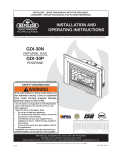
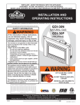
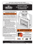
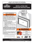
1
INSTALLER: THESE INSTRUCTIONS MUST BE CONVEYED TO AND REMAIN WITH THE HOMEOWNER.
CERTIFIED UNDER CANADIAN AND AMERICAN NATIONAL STANDARDS, CSA 2.33, ANSI Z21.88 FOR VENTED GAS FIREPLACE HEATERS
GAS INSERT
INSTALLATION AND OPERATION INSTRUCTIONS FOR
GAS-FIRED VENTED ROOM HEATER
NATURAL GAS MODEL
PROPANE GAS MODEL
GI3016-N
GI3016-P
GAS-ZERO CLEARANCE WHEN INSTALLED WITH GI-700 KIT (FLUSH FRONT & LOUVRES)
WITHOUT GI-700 KIT INSTALL RECESSED INTO A WOODBURNING NON-COMBUSTIBLE FIREPLACE
CERTIFICATION LABEL AFFIXED TO UNDERSIDE OF FRESH AIR DAMPER
WARNING: If the information in these instructions is not followed exactly, a fire or
explosion may result causing property damage, personal injury or death.
FOR YOUR SAFETY
Do not store or use gasoline or other flammable vapours and liquids in the vicinity
of this or any other appliance.
WHAT TO DO IF YOU SMELL GAS:
• Immediately call your gas supplier from
• Do not try to light any appliance.
a neighbor's phone. Follow the gas sup• Do not touch any electrical switch.
• Do not use any phone in your building. plier's instructions.
• If you cannot reach your gas supplier,
call the fire department.
Installation and service must be performed by a qualified installer, service
agency or the gas supplier.
Wolf Steel Ltd., 24 Napoleon Rd., Barrie, ON L4M 4Y8 Canada • (705)721-1212 • fax(705)722-6031
www.napoleonfireplaces.com • [email protected]
W415-0171 / D / 01.06.04
2
TABLE of CONTENTS
PG 2-5
INTRODUCTION
10-11
Warranty
General Instructions
Mantle Clearance
General Information
Care of Glass, Enamelled & Plated Parts
5-6
INSTALLATION
6-9
Operating Instructions
Fresh Air Damper System
Maintenance
11
BLOWER INSTALLATION
Blower Replacement Instructions
11
Gas Installation
Spill Switch
Venting Action Check
OPERATION / MAINTENANCE
ADJUSTMENTS
Venturi Adjustments
Pilot Burner Adjustment
12-13
FINISHING
Brick Panel Installation
Log Placement/Charcoal Embers
Glass, Flashing Kit, Logo Placement,
Louvre, Inset & Bay Kit Installation
REPLACEMENTS
Ordering Replacement Parts
Replacement Parts
Accessories
14-15
TROUBLE SHOOTING GUIDE
PLEASE RETAIN THIS MANUAL FOR FUTURE REFERENCE
WARNING
• Adults and especially children should be alerted to
the hazards of high surface temperatures and should
stay away to avoid burns or clothing ignition. Supervise young children when they are in the same
room as the fireplace.
• Clothing or other flammable material should not be
placed on or near the fireplace.
• Any safety screen or guard removed for servicing
must be replaced prior to operating the fireplace.
• This fireplace must not be connected to a chimney
flue pipe serving a separate solid fuel burning appliance.
• Do not operate the fireplace with the glass door
removed, cracked or broken. Replacement of the
glass should be done by a licensed or qualified service person.
• Do not strike or slam shut the fireplace glass door.
• Due to high temperatures, the fireplace should be
located out of traffic and away from furniture and
draperies.
• It is imperative that the control compartments,
burners and circulating blower and its passageway
in the fireplace and venting system are kept clean.
The fireplace and its venting system should be inspected before use and at least annually by a qualified service person. More frequent cleaning may
be required due to excessive lint from carpeting,
bedding material, etc. The fireplace area must be
kept clear and free from combustible materials,
gasoline and other flammable vapours and liquids.
• Do not use this fireplace if any part has been under
water. Immediately call a qualified service technician to inspect the fireplace and to replace any part
of the control system and any gas control which
has been under water.
• Under no circumstances should this fireplace be
modified.
• Do not burn wood or other materials in this fireplace.
NOTE: CHANGES, OTHER THAN EDITORIAL, ARE DENOTED BY A VERTICAL LINE IN THE MARGIN
W415-0171 / D / 01.06.04
3
NAPOLEON gas fireplaces are manufactured under the strict Standard of the world recognized
ISO 9001 : 2000 Quality Assurance Certificate.
NAPOLEON products are designed with superior components and materials, assembled by trained craftsmen
who take great pride in their work. The burner and valve assembly are leak and test-fired at a quality test
station. The complete fireplace is thoroughly inspected by a qualified technician before packaging to ensure that
you, the customer, receives the quality product that you expect from NAPOLEON.
NAPOLEON GAS FIREPLACE PRESIDENT'S LIFETIME LIMITED WARRANTY
The following materials and workmanship in your new NAPOLEON gas fireplace are
warranted against defects for as long as you own the fireplace. This covers: combustion
chamber, heat exchanger, stainless steel burner, phazer™ logs and embers, ceramic glass
(thermal breakage only), gold plated parts against tarnishing, porcelainized enamelled components and aluminum extrusion trims.
Electrical (110V and millivolt) components and wearable parts such as blowers, gas valves,
thermal switch, switches, wiring, remote controls, ignitor, gasketing, and pilot assembly are
covered and NAPOLEON will provide replacement parts free of charge during the first year
of the limited warranty.
Labour related to warranty repair is covered free of charge during the first year. Repair
work, however, requires the prior approval of an authorized company official. Labour costs
to the account of NAPOLEON are based on a predetermined rate schedule and any repair
work must be done through an authorized NAPOLEON dealer.
CONDITIONS AND LIMITATIONS
NAPOLEON warrants its products against manufacturing defects to the original purchaser only -- i.e., the individual or legal entity (registered customer) whose name appears on the
warranty registration card filed with NAPOLEON -- provided that the purchase was made through an authorized NAPOLEON dealer and is subject to the following conditions and limitations:
This factory warranty is nontransferable and may not be extended whatsoever by any of our representatives.
The gas fireplace must be installed by a licenced, authorized service technician or contractor. Installation must be done in accordance with the installation instructions included with the
product and all local and national building and fire codes.
This limited warranty does not cover damages caused by misuse, lack of maintenance, accident, alterations, abuse or neglect and parts installed from other manufacturers will nullify this
warranty.
This limited warranty further does not cover any scratches, dents, corrosion or discolouring caused by excessive heat, abrasive and chemical cleaners nor chipping on porcelain enamel
parts, mechanical breakage of PHAZER™ logs and embers, nor any venting components used in the installation of the fireplace.
NAPOLEON warrants its stainless steel burners against defects in workmanship and material for life, subject to the following conditions: During the first 10 years NAPOLEON will replace
or repair the defective parts at our option free of charge. From 10 years to life, NAPOLEON will provide replacement burners at 50% of the current retail price.
In the first year only, this warranty extends to the repair or replacement of warranted parts which are defective in material or workmanship provided that the product has been operated in
accordance with the operation instructions and under normal conditions.
After the first year, with respect to this President's Limited Lifetime Warranty, NAPOLEON may, at its discretion, fully discharge all obligations with respect to this warranty by refunding
to the original warranted purchaser the wholesale price of any warranted but defective part(s).
After the first year, NAPOLEON will not be responsible for installation, labour or any other costs or expenses related to the reinstallation of a warranted part, and such expenses are not
covered by this warranty.
Notwithstanding any provisions contained in this President's Limited Lifetime Warranty, NAPOLEON’S responsibility under this warranty is defined as above and it shall not in any event
extend to any incidental, consequential or indirect damages.
This warranty defines the obligations and liability of NAPOLEON with respect to the NAPOLEON gas fireplace and any other warranties expressed or implied with respect to this product,
its components or accessories are excluded.
NAPOLEON neither assumes, nor authorizes any third party to assume, on its behalf, any other liabilities with respect to the sale of this product. NAPOLEON will not be responsible for:
over-firing, downdrafts, spillage caused by environmental conditions such as rooftops, buildings, nearby trees, hills, mountains, inadequate vents or ventilation, excessive venting configurations, insufficient makeup air, or negative air pressures which may or may not be caused by mechanical systems such as exhaust fans, furnaces, clothes dryers, etc.
Any damages to fireplace, combustion chamber, heat exchanger, brass trim or other component due to water, weather damage, long periods of dampness, condensation, damaging
chemicals or cleaners will not be the responsibility of NAPOLEON.
The bill of sale or copy will be required together with a serial number and a model number when making any warranty claims from your authorized dealer. The warranty registration card
must be returned within fourteen days to register the warranty.
NAPOLEON reserves the right to have its representative inspect any product or part thereof prior to honouring any warranty claim.
ALL SPECIFICATIONS AND DESIGNS ARE SUBJECT TO CHANGE WITHOUT PRIOR NOTICE DUE TO ON-GOING PRODUCT IMPROVEMENTS. NAPOLEON® IS A REGISTERED
TRADEMARK OF WOLF STEEL LTD. PATENTS U.S. 5.303.693.801 - CAN. 2.073.411, 2.082.915 & DES 417,497(12.07.1999). © WOLF STEEL LTD.
W415-0171 / D / 01.06.04
4
GENERAL INSTRUCTIONS
Installation practices vary from region to region and it is
important to know the specifics that apply to your area,
for example: in Massachusetts State:
• The fireplace damper must be removed or welded in the open
position prior to installation of a fireplace insert or gas log.
• The appliance off valve must be a “T” handle gas cock.
• The flexible connector must not be longer than 36 inches.
• The appliance is not approved for installation in a bedroom or
bathroom unless the unit is a direct vent sealed combustion
product.
• WARNING: This product must be installed by a licensed plumber
or gas fitter when installed within the commonwealth of
Massachusetts.
In absence of local codes, install to the current CAN1-B149
Installation Code in Canada or to the National Fuel Gas
Code, ANSI Z223.1, and NFPA 54 in the United States.
Purge all gas lines with the glass door of the fireplace
removed. Assure that a continuous gas flow is at the
burner before installing the door.
Under extreme vent configurations, allow several minutes
(5-15) for the flame to stabilize after ignition. Altitudes
greater than 4,000 ft. require a minimum vent run of 12 ft.
The heater and its individual shutoff valve must be disconnected from the gas supply piping system during any pressure
testing of that system at test pressures in excess of ½ psig (3.5
kPa). The fireplace must be isolated from the gas supply piping system by closing its individual manual shutoff valve during
any pressure testing of the gas supply piping system at test
pressures equal to or less than ½ psig (3.5 kPa).
A 1/8 inch NPT plug, accessible for test gauge connection,
must be installed immediately upstream of the gas supply
connection to the fireplace.
This fireplace must be connected to any accepted lined chimney system listed to ULC-S635M (in Canada) or UL-1777
(in USA). The venting connection must be in compliance
with the chimney manufacturers installation instructions.
The draft hood must be installed so that it is in the same
atmospheric pressure zone as the combustion air inlet to
the fireplace.
This heater can be installed two different ways. If installed
as is, it must be recessed into a vented noncombustible
woodburning fireplace (prefabricated or masonry) only. This
is referred to as an INSERT type of installation.
The minimum fireplace size in which the heater is to be
installed is: HEIGHT 21 inches
WIDTH 26½ inches
DEPTH 17½ inches
If installed in conjunction with kit #GI-700, it may be framed
into an enclosure made of combustible materials. This is
referred to as a ZERO CLEARANCE type of installation.
This heater may only be installed in the GI-700 when using
the glass front kit, GI-FF, as well as one louvre kit, GI-LPB,
GI-LAB, GI-LG or GI-LK. The minimum clearance to combustible construction in this form of installation is:
MANTLE HEIGHT*
7 inches**
SIDES, BACK, BOTTOM & TOP
0 inches
B-VENT
1 inch
RECESSED DEPTH
18½ inches
* MEASUREMENTS TAKEN FROM KIT STANDOFFS. SEE KIT INSTRUCTIONS
**MAXIMUM HORIZONTAL EXTENSION IS 6 INCHES.
Objects placed in front of the fireplace must be kept a
minimum of 48" away from the front face.
W415-0171 / D / 01.06.04
The fireplace, when installed, must be electrically connected and grounded in accordance with local codes. In
the absence of local codes, use the current CSA C22.1
CANADIAN ELECTRICAL CODE in Canada or the
ANSI/NFPA 70 NATIONAL ELECTRICAL CODE in the United
States. The blower power cord must be connected into a
properly grounded receptacle. The grounding prong must
not be removed from the cord plug.
Provide adequate ventilation and combustion air. Provide adequate accessibility clearance for servicing and
operating the fireplace. Never obstruct the front opening of the fireplace.
MANTLE CLEARANCE
Mantle clearance, while
conforming to the
stated clearance to
combustible materials,
can vary according to
the mantle depth.
These clearances do
not apply to a GI-700 kit
type installation.
FIGURE 1
GENERAL INFORMATION
FOR YOUR SATISFACTION, THIS FIREPLACE HAS BEEN
TEST-FIRED TO ASSURE ITS OPERATION AND QUALITY! Maximum input is 30,000 BTU/hr for natural gas and
24,000 BTU/hr for propane. When the fireplace is installed
at elevations above 4,500 ft., and in the absence of specific recommendations from the local authority having jurisdiction, the certified high altitude input rating shall be
reduced at the rate of 4% for each additional 1,000 ft. Maximum output for natural gas is 22,800 BTU/hr at an efficiency of 76% with the fan on, 72% with the fan off; and
18,240 BTU/hr for propane at an efficiency of 76% with the
fan on, 71% with the fan off. Minimum A.F.U.E.(Annual Fuel
Utilization Efficiency) rating is 64% for both natural and
propane gas. Where the fireplace has been factory
equipped for hi-altitude, the input has been downrated by
10%. This fireplace is approved for bathroom, bedroom
and bed-sitting room installations and is suitable for mobile home installation.
Minimum inlet gas supply pressure is 4.5 inches water
column for natural gas and 11 inches water column for
propane. Maximum inlet gas pressure is 7 inches water
column for natural gas and 13 inches water column for
propane. Manifold pressure under flow conditions is 3.5
inches water column for natural gas and 10 inches water
column for propane.
No external electricity (110 volts or 24 volts) is required
for the gas system operation.
Change in flame appearance from "HI" to "LO" is more
evident in natural gas than in propane. The self generating
pilot provides current for a remote burner On-Off switch.
5
CARE OF GLASS, ENAMELLED AND PLATED PARTS
Do not use abrasive cleaners to clean these parts. Buff
lightly with a clean dry cloth. Porcelain enamelled components must be handled with care. The baked-on finish is
glasslike. If struck, it will chip! Touch-up paint is available
through your Napoleon dealer.
The glass is 3/16" ceramic glass available from your Napoleon dealer. DO NOT SUBSTITUTE MATERIALS. Clean
the glass after the first 10 hours of operation with a recommended gas fireplace glass cleaner. Thereafter clean as
required. DO NOT CLEAN GLASS WHEN HOT! If the glass
is not kept clean permanent discolouration and / or blemishes may result.
INSTALLATION
FIGURE 2
Clean out the ashes from the inside of the woodburning
fireplace. Make sure that the chimney and woodburning
fireplace are in clean and sound condition. Do not remove
bricks or mortar from the masonry fireplace. If necessary
have any repair work done by a qualified person before
installing the insert. Remove the existing fireplace damper
or lock into an open position. Line the chimney with a 4
inch diameter approved liner. Pack insulation around the
liner in the damper area to prevent air flow from entering
the chimney. Chimney installation must conform to both
national and local code requirements. The liner must be
continuous from the fireplace to the chimney cap.
FIGURE 3
Remove the securing screw from the front of the dilution
plate. Push the dilution hood out of its securing clip and
attach the liner using 3 screws equally spaced. Move the
insert into the centre of the woodburning fireplace making
sure that the dilution draft hood inserts back into its securing clip. Level using the four levelling screws located front
and back on either side of the fireplace base.
Levelling the insert will eliminate rocking or excessive
noise when the fan is in operation. Replace the securing
screw to the front of the dilution plate.
FIGURE 5
Install rigid black pipe, a flex connector, if local codes permit, or 1/2" type L, copper tubing with a 3/8" to 1/2" adapter
and a shut off valve to the fireplace. Seal and tighten securely. The adapter will be required between the gas valve
and the copper tubing or flex connector.
Do not damage or kink flex connector!
Check for gas leaks by brushing on a soap and water
solution.
Do not use open flame!
An on/off switch has been included and can be located at
the lower right, behind the louvre access door or at the
right side trim.
For ease of accessibility, this switch may be replaced with
a wall switch or substituted with a millivolt thermostat that
may be installed in a convenient location on any wall. Route
2-strand (solid core) millivolt wire through the electrical
hole located at the bottom right side of the unit. The recommended maximum lead length depends on wire size:
WIRE SIZE
MAX. LENGTH
14gauge
100 feet
16gauge
60 feet
18gauge
40 feet
1
FIGURE 4
2
3
FIGURE 6
Attach the two leads to terminals 1 and 3 located on the
gas valve.
Do not connect either the wall switch or the gas valve to
electricity (110 volts or 24 volts).
W415-0171 / D / 01.06.04
6
SPILL SWITCH
VENTING ACTION CHECK
This is a thermally activated switch, attached to the back of
the unit and extending up into the dilution draft hood, which
senses the change in temperature and shuts down the
gas valve in the event of a severe downdraft of air or a
blocked or disconnected vent. It acts as a safety shutoff to
prevent a build up of carbon monoxide or an explosion of
unburnt gases during start up. If the flue is blocked or has
no "draw", the spill switch will automatically shut off the
supply of gas within about 5-10 minutes.
A check for correct venting action must be made before
the installed insert is left with the customer.
Test after installing the unit into either the GI-700 ZERO
CLEARANCE KIT or a vented noncombustible fireplace in
the following manner:
1. Close all doors and windows in the room / start exhaust
fans in the home / turn fireplace blower off.
2. Set controls to "high" and light the unit.
3. Wait 5 minutes. Light a match and hold it to the spill tube
opening.
4. Venting action is satisfactory if smoke is drawn into the
spill tube. Venting action is unsatisfactory if the flame and
smoke are not drawn into the tube.
5. If venting action is unsatisfactory, turn the unit off, wait
10 minutes and try again. If the smoke or flame is still not
drawn into the spill tube, turn the unit off and check for
adequate fresh air supply, vent blockage or restriction. If
necessary, consult with a qualified inspector.
FIGURE 7
FIGURE 8
TAMPERING WITH THE SWITCH CAN RESULT IN
CARBON MONOXIDE (CO) POISONING AND POSSIBLE DEATH.
FINISHING
OPTIONAL BRICK PANEL INSTALLATION
Remove the securing screws located on either of
the firebox sides
as
illustrated.
Remove protective
plastic wrap from
all four panels.
Centre the rear
brick
panel
against the back of
the firebox. Place
the left brick panel
against the left
side of the firebox,
ensuring that it
butts up to the rear
FIGURE 9a
panel.
Excess material may be trimmed with a utility knife. Secure
in place using a retainer bracket and 2 of the screws. Repeat for the right side.
W415-0171 / D / 01.06.04
FIGURE 9b
When shipped, the brick panels range in colour from
white to varying shades of brown. During initial use, the
panels will darken temporarily and emit a slight odour
for a few hours. This is a normal condition that will not
occur again. Simply open a window to sufficiently ventilate the room. The appearance of the panels will permanently lighten in colour with use.
7
LOG PLACEMENT
TM
PHAZER logs and charcoal embers, exclusive to Napoleon Fireplaces, provide a unique and realistic glowing
effect that is different in every installation. Take the time to
carefully position the charcoal embers for a maximum glowing effect.
POSITIONING THE LOGS IMPROPERLY WILL CAUSE
FLAME IMPINGEMENT AND CARBONING.
FIGURE 10
1. Place the front log onto the main burner, pushing it as
close as possible to the burner ports without
blocking/covering them. The left and right spacing between
the log ends and the burner ports should be equal.
2. Place the back log onto the log support brackets located
on the rear wall of the combustion chamber. The notch
situated at the lower left of the back log should be centred
evenly above the pilot assembly.
3. While supporting the back log, to prevent it from falling
forward, set the three smaller logs into the pockets and
grooves of the front and back logs, respectively.
CHARCOAL EMBERS
Randomly place the embers along the front burner ports.
Keep ember dust away from burner ports to avoid plugging
them.
Fine dust found in bottom of bag not to be used.
PHAZERTM logs and charcoal embers glow when exposed
to direct flame. Use only certified PHAZERTM logs and charcoal embers available from your Napoleon dealer.
Log colours may vary. During the initial use of the fireplace, the colours will become more uniform as colour
pigments burn in during the heat activated curing process.
FIGURE 11
W415-0171 / D / 01.06.04
8
FLUSH GLASS FRONT KIT, GI-FF
Attach the lower glass bracket.
Seat the glass inside the bracket
and using two screws attach the
upper glass bracket, as shown.
FLUSH LOUVRE KIT, GI-1L
FIGURE 12a
UPPER
LOUVRE
SIDE VIEW
LOUVRE
CLIP
FLASHING SURROUND KITS, GI-900 / GI-909
Assemble the flashing and mount to the inside of the outer
shell using 4 securing screws (supplied with the louvre
kit).
FIGURE 12b
SECURING SCREW
LOCATIONS
LOWER GLASS BRACKET
LOGO PLACEMENT
FIGURE 14
FIGURE 13
13/8"
LOGO
11/8"
Remove the backing of the logo supplied and place on the
glass viewing area, as indicated.
W415-0171 / D / 01.06.04
UPPER LOUVRES
Insert the back edge of the upper louvre into the upper
louvre clips.
LOWER LOUVRES
Secure the lower louvre assembly to the insert, using the 4
screws supplied.
9
ORNAMENTAL FLUSH INSETS, GI-OI
FIGURE 17
Assemble the flashing and mount to the inside of the outer
shell using 4 securing screws and spacers (supplied) as
shown. Hook the ornamental inlays over the spacers.
FIGURES 15
UPPER
LOWER
FIGURE 18
ORNAMENTAL BAY INSETS, GI-OI
FIGURE 19
BAY GLASS FRONT, GI-BF
With the bay chassis on
a flat surface, insert the
front glass (bottom first)
and centred to the mitred
edges of the chassis.
RETAINER TAB
Fit the bevelled edge of
the each side glass piece
tightly to either edge of the
front glass.
Secure the glass by bendFIGURES 16
ing up the retainer tabs at
the top and bottom.
Spread and insert the
spring clips between the
side glass and the chasSPRING CLIP
sis (2 per side).
Place the front brick panel
pieces into place at the bottom.
Secure the bay to the insert front at the top and bottom
outside corners using 4 screws.
Both these options may be
attached to the insert front
using 4 magnets, positioned as shown:
NOTE:The ornamental bay
inlays can be adjusted to
align with the bay door assembly.
FIGURE 20
MAGNET
BAY LOUVRES, GIB-L
Note: Black louvre assembly, if supplied, must be installed
as uppers, due to the high fireplace temperature.
MAGNET
W415-0171 / D / 01.06.04
10
OPERATION / MAINTENANCE
OPERATING INSTRUCTIONS
FRESH AIR DAMPER SYSTEM
When lit for the first time, the stove will emit a slight odour
for a few hours. This is a normal temporary condition
caused by the curing of the logs and the "burn-in" of internal paints and lubricants used in the manufacturing process and will not occur again.
Simply open a window to sufficiently ventilate the room.
After extended periods of non-operation such as following
a vacation or a warm weather season, the fireplace may
emit a slight odour for a few hours. This is caused by dust
particles in the heat exchanger burning off. Open a window
to sufficiently ventilate the room.
If your masonry fireplace is equipped with a fresh air inlet
in the floor of the firebrick chamber, the insert is able to
take outside air directly into the unit through an opening in
its base thereby eliminating the need to use preheated
room air for combustion. The flow of air may be adjusted
through the use of a damper located below the louvre access door. The damper should be kept closed (pushed all
the way in) when the unit is not in operation or if no outside
air is available. The damper is fully open when pulled forward (one inch from the closed position).
FIGURE 22
Never obstruct the flow of combustion or
ventilation air.
FOR YOUR SAFETY READ BEFORE LIGHTING:
A This stove has a pilot which must be lit by hand while
following these instructions exactly.
B Before lighting, smell all around the fireplace area for
gas and next to the floor because some gas is heavier
than air and will settle on the floor.
C Use only your hand to push in or turn the gas control
knob. Never use tools. If the knob will not push in or turn
by hand, do not try to repair it.
Call a qualified service technician. Force or attempted
repair may result in a fire or explosion.
D Do not use this insert if any part has been under water.
Immediately call a qualified service technician to inspect
the unit and replace any part of the control system and
any gas control touched by water.
WHAT TO DO IF YOU SMELL GAS:
• Do not try to light any appliance.
• Do not touch any electrical switch; do not use any phone
in your building.
• Immediately call your gas supplier from a neighbour's
phone. Follow the gas supplier's instructions.
• If you cannot reach your gas supplier, call the fire department.
LIGHTING INSTRUCTIONS
1. Stop! Read all the safety information above. When
lighting and relighting, the gas knob cannot be turned
from "pilot" to "off" unless the knob is depressed.
2. Turn off all electrical power to the stove.
3. Turn the gas knob
clockwise to off.
4. Wait 5 minutes for any gas in the combustion chamber to escape. Continue to the next step if you do NOT
smell any gas. If you smell gas, STOP! and follow the
instructions in "What to do if You Smell Gas" listed above.
5. If the unit is equipped with a flame adjustment valve,
turn clockwise to off.
6. Locate the pilot situated in front of the rear log.
"pi7. Turn the gas knob counter-clockwise to
lot" position.
8. Depress and hold the gas knob while lighting the pilot
with the push button igniter. Keep the knob fully depressed for one (1) minute, then release. If the pilot does
not continue to burn, repeat steps 3 through 7.
9. With the pilot lit, turn the gas knob counter-clockwise
to "on" position.
10. If your insert is equipped with a flame adjustment
valve, push and turn the knob to "high".
11. If your insert is equipped with a remote "on-off" switch,
the main burner may not come on when you turn the gas
valve to "on" or "high". The remote switch must be in the
THERMOPIL
"on" position as well to ignite the main burner.
12. Turn on all electrical power to the insert.
PILOT BURNER
GAS VALVE
ELECTRODE
TO TURN OFF GAS
1. Turn off all electrical power to the unit if service is
to be performed.
W415-0171 / D / 01.06.04
2. Push in gas control knob slightly and turn clockwise to off.
Do not force.
11
MAINTENANCE
TURN OFF THE GAS AND ELECTRICAL POWER
BEFORE SERVICING THE FIREPLACE.
CAUTION: Label all wires prior to disconnection when servicing controls. Wiring errors can cause improper and dangerous operation. Verify proper operation after servicing.
This insert and its venting system should be inspected
before use and at least annually by a qualified service person. The fireplace area must be kept clear and free of
combustible materials, gasoline or other flammable vapours and liquids. The flow of combustion and ventilation
air must not be obstructed.
1. In order to properly clean the burner and pilot assembly,
remove the logs to expose both assemblies.
2. Keep the control compartment, logs, burner, air shutter
opening and the area surrounding the logs clean by vacuuming or brushing, at least once a year.
3. Check to see that all burner ports are burning. Clean out
any of the ports which may not be burning or are not burning properly. (right brick panel must be removed in order to
facilitate burner removal)
4. Check to see that the pilot flame is large enough to
engulf the thermopile on one leg and reaches toward the
burner on the other leg.
5. Replace the cleaned logs.
6. Check to see that the main burner ignites completely on
all openings when the gas knob for the burner is turned
on. A 5 to 10 second total light-up period is satisfactory. If
ignition takes longer, consult your Napoleon dealer / distributor.
7. Check that the gasketing on the door is not broken or
missing. Replace if necessary.
BLOWER REPLACEMENT INSTALLATION
BLOWER SYSTEM
The Napoleon gas fireplace insert comes standard with a
blower, a heat sensor, variable on/off speed control and a
power cord. Because the blower is thermally activated,
when turned on, it will automatically start approximately 15
minutes after lighting the fireplace and will run for approximately 30 minutes after the fireplace has been turned off.
Use of the fan increases the output of heat. Air, drawn in
through the lower louvre access door, is driven up the back
of the firebox, and exhausted as hot air between the upper
louvres.
FIGURE 21
BLOWER REPLACEMENT INSTRUCTIONS
•
•
•
•
•
•
•
•
Turn off the gas and electric power to the unit.
Remove the glass door.
Remove the lower glass bracket.
Remove the logs.
Remove the burner assembly. (right brick panel must
be removed in order to facilitate removal)
Remove the four screws holding the access door in
place on the control assembly (located to the back of
the burner assembly.) For location, see picture in replacement parts.
Disconnect the electrical connectors at the blower.
Remove the blower.
Drywall dust will penetrate into blower bearings causing irrepairable damage and must be prevented from coming into
contact with the blower or its compartment.
Any damage resulting from this condition is not covered by the warranty policy.
ADJUSTMENTS
VENTURI ADJUSTMENT
PILOT BURNER ADJUSTMENT
Natural gas models have air shutters set at 1/16 (.063")
inch open. Propane gas models have air shutters set at [5/
16] (.313) inch open. Closing the air shutter will cause a
more yellow flame, but can lead to carboning. Opening the
air shutter will cause a more blue flame, but can cause
flame lifting from the burner ports. The flame may not appear yellow immediately; allow 15 to 30 minutes for the
final flame colour to be established.
AIR SHUTTER ADJUSTMENT MUST ONLY BE DONE BY A
QUALIFIED GAS INSTALLER!
1. Remove the pilot adjustment cap.
2. Adjust the pilot screw to provide properly sized flame.
3. Replace the pilot adjustment cap.
THERMOPILE
FIGURE 24
FIGURE 23
PILOT ADJUSTMENT
CAP
PILOT ASSEMBLY
FIGURE 25
FLAME MUST ENVELOP UPPER
3
/16" TO ½" OF THERMOPILE
W415-0171 / D / 01.06.04
12
REPLACEMENTS
Contact your dealer for questions concerning prices and
availability of replacement parts. Normally all parts can be
ordered through your Napoleon dealer or distributor.
FOR WARRANTY REPL
ACEMENT PAR
TS, A PHO
TOCOPY OF THE
REPLA
ARTS
PHOT
ORIGINAL INVOICE WILL BE REQUIRED TO HONOUR THE CLAIM.
* IDENTIFIES ITEMS WHICH ARE NOT ILLUSTRATED. FOR FURTHER INFORMATION, CONTACT YOUR NAPOLEON DEALER.
When ordering replacement parts always give the following
information:
1. MODEL & SERIAL NUMBER OF FIREPLACE
2. INSTALLATION DATE OF FIREPLACE
3. PART NUMBER
4. DESCRIPTION OF PART
5. FINISH
ACCESSORIES:
REPLACEMENT PARTS
#
PART NO.DESCRIPTION
#
PART NO.DESCRIPTION
1
2
2
3
3
3
3
4*
4*
5
5
6
7
8*
9*
10
11
12
13
14
15
16*
17
18
18
19*
20*
21
GZ-551
W725-0036
W725-0037
W455-0004
W455-0003
W455-0013
W455-0002
W660-0007
W660-0006
W010-0337
W010-0338
W357-0001
W680-0004
W690-0002
W660-0009
W135-0007
W135-0052
W135-0015
W135-0009
W135-0016
GL-610
W550-0001
W010-0333
W455-0025
W455-0006
W385-0245
W562-0012
KB 35
22
23*
24*
25
26*
27*
28
28
28
28
GI-FF
W300-0012
W562-0011
GI-BF
W010-0325
W010-0326
GI-1LK
GI-1LPB
GI-1LAB
GI-1LSS
28
29
29
29
29
29
GI-1LG
GIB-LK
GIB-LPB
GIB-LAB
GIB-LG
GIB-LSS
30
30
31
GI-OIK
GI-OIG
GIB-OIK
31
32
33*
34
35
36*
37*
38*
39*
40
40
40
40
40
40
40
40
40
40
40
40
40
40
41*
41*
41*
GIB-OIG
GI 778KT
W470-0002
GI 700KT
111-KT
W690-0001
W660-0011
GD 660
W500-0033
GI-900AB6
GI-900B6
GI-900K6
GI-900AB9
GI-900B9
GI-900SS6
GI-900SS9
GI-900K9
GI-909S6
GI-909F6
GI-909K6
GI-909S9
GI-909F9
GI-909K9
W175-0145
W175-0146
W175-0148
REPLACEMENT BLOWER
NATURAL GAS VALVE C/W ADJUSTABLE REGULATOR
PROPANE GAS VALVE C/W ADJUSTABLE REGULATOR
#36 DMS NATURAL GAS BURNER ORIFICE
#54 DMS PROPANE GAS BURNER ORIFICE
#37 DMS NATURAL GAS BURNER ORIFICE - HIALT
#55 DMS PROPANE GAS BURNER ORIFICE - HIALT
SPILL SWITCH (NATURAL GAS)
SPILL SWITCH (PROPANE)
NATURAL GAS PILOT ASSEMBLY
PROPANE GAS PILOT ASSEMBLY
PIEZO IGNITER
THERMOPILE
THERMAL SENSING SWITCH
BURNER ON/OFF SWITCH
BACK LOG
FRONT LOG
RIGHT LOG
CENTER LOG
LEFT LOG
LOG SET c/w CHARCOAL EMBERS
CHARCOAL EMBERS
BURNER ASSEMBLY
NATURAL GAS PILOT INJECTOR
PROPANE GAS PILOT INJECTOR
NAPOLEON LOGO
DOOR GASKET (2PC - SIDE)
VARIABLE SPEED SWITCH
W415-0171 / D / 01.06.04
FLUSH GLASS DOOR ASSEMBLY
DOOR GLASS
DOOR GASKET - TOP
BAY GLASS DOOR ASSEMBLY
SIDE BAY DOOR GLASS -EACH C/W GASKET
FRONT BAY DOOR GLASS C/W GASKET
BLACK UPPER & LOWER LOUVRES
BLACK UPPER & POLISHED BRASS LOWER LOUVRES
BLACK UPPER & ANTIQUE BRASS LOWER LOUVRES
BLACK UPPER & BRUSHED STAINLESS STEEL
LOWER LOUVRES
GOLD PLATED UPPER & LOWER LOUVRES
BLACK BAY LOUVRES C/W TRIM
POLISHED BRASS BAY LOWER LOUVRES C/W TRIM
ANTIQUE BRASS BAY LOWER LOUVRES C/W TRIM
GOLD PLATED BAY LOUVRE ASSEMBLY
BRUSHED STAINLESS STEEL BAY
LOWER LOUVRES C/W TRIM
BLACK INSET W/ POLISHED BRASS LOWER DOOR TRIM
GOLD PLATED ORNAMENTAL INSETS
BLACK BAY ORNAMENTAL INSETS
C / W LOWER DOOR TRIM
GOLD PLATED BAY ORNAMENTAL INSETS
BRICK PANEL KIT
ENAMEL TOUCH UP AND BRUSH (SPECIFY COLOUR)
ZERO CLEARANCE SHELL
OUTSIDE AIR KIT
MILLIVOLT THERMOSTAT
REMOTE CONTROL - ADVANTAGE PLUS
WALL SWITCH/20FT WIRE
V.S.S. MOUNTING PLATE FOR WALL SWITCH
ANTIQUE BRASS FLASHINGS - 6"
POLISHED BRASS FLASHINGS - 6"
BLACK FLASHINGS - 6"
ANTIQUE BRASS FLASHINGS - 9"
POLISHED BRASS FLASHINGS - 9"
BRUSHED STAINLESS STEEL FLASHINGS - 6"
BRUSHED STAINLESS STEEL FLASHINGS - 9"
BLACK FLASHINGS - 9"
PORCELAIN ALMOND FLASHINGS - 6"
PORCELAIN GREEN FLASHINGS - 6"
PORCELAIN BLACK FLASHINGS - 6"
PORCELAIN ALMOND FLASHINGS - 9"
PORCELAIN GREEN FLASHINGS - 9"
PORCELAIN BLACK FLASHINGS - 9"
CONVERSION KIT - NAT - LP
HIGH ALTITUDE CONVERSION KIT - NG - LP
HIGH ALTITUDE CONVERSION KIT - NG - NG
13
W415-0171 / D / 01.06.04
14
TROUBLE SHOOTING GUIDE
BEFORE
ATTEMPTING TO TROUBLESHOOT, PURGE YOUR UNIT AND INITIALLY LIGHT THE PILOT AND THE MAIN BURNER WITH THE GLASS DOOR REMOVED.
SYMPTOM
PROBLEM
Pilot goes out when the A - System is not correctly
gas knob is released. purged.
B - Out of propane gas.
C - Pilot flame is not
large enough
D - Pilot flame is not engulfing
the thermopile.
E - Thermopile shorting.
F - Faulty thermopile.
G - Faulty valve.
Pilot burning; no gas to
main burner; gas knob
is on; wall switch is on;
heat/flame adjustment
valve is on (if so
equipped.
Pilot goes out while
standing; Main burner
is in 'OFF' position.
Pilot will not light.
- fill the tank and purge the gas line with the glass door
removed.
- turn up the pilot flame.
- gently twist the pilot head to improve the flame pattern
around the thermopile.
- clean thermopile and valve connection.
- check that thermopile insulation is not frayed and grounding out on the housing or the burner support.
- replace thermopile.
- replace valve.
- test & replace if necessary.
- test & replace if necessary.
- connect a jumper wire across the wall switch terminals;
if the main burner lights, replace the wall switch.
B - Wall switch wiring is defective.
- disconnect switch wires from valve and connect a jumper
wire across terminals 1 and 3; if the main burner lights,
check the wires for defects and/or replace wires.
C- Main burner orifice is
plugged.
- remove stoppage in orifice.
D - Remote gas valve operator
is defective.
- connect a jumper wire across terminals 1 and 3; if main
burner does not light, replace gas valve.
Gas piping is undersized.
- turn on all gas appliances and see if pilot flame flutters,
diminishes or extinguishes, especially when main burners
ignite. Monitor supply pressure.
- check if supply piping size is to code. Correct all undersized piping.
A - No spark at pilot burner
- check that the wire is connected to the push button ignitor.
- check if the push button ignitor needs tightening.
- replace pilot assembly if the wire insulation is broken or
frayed.
- replace pilot assembly if the ceramic insulator is cracked
or broken.
- replace the push button ignitor.
B - Spark gap is incorrect
- spark gap should be 1/16" to 1/8" from the electrode tip
and the pilot burner. Light the pilot with a match and adjust
the electrode tip to the required spark gap and proper location.
C - No gas at the pilot burner
- check that the manual valve is turned on.
- check the pilot orifice for blockage.
- replace the valve.
- call the gas distributor.
- fill the tank and purge the gas line with the glass door
removed.
/16" TO 1/8"
W415-0171 / D / 01.06.04
- purge the gas line with the glass door removed.
A - Wall switch is defective
1
PIEZO
IGNITER
THERMOP I L O T
PILE
BURNER
TEST SOLUTION
D - Out of propane gas
15
SYMPTOM
Main burner goes out;
pilot goes out.
PROBLEM
TEST SOLUTION
A - Refer to "Main burner goes out; pilot stays on"
B - Chimney down-drafting
C - Chimney is blocked
D - Liner disconnected from insert.
E - Faulty spill switch.
- wait ten minutes. Shut off all exhaust fans in the house
(ie: kitchen and bathrooms), furnace, and clothes dryer.
Open windows and/or doors. Start fireplace and monitor its
operation.
Close doors and windows and start appliances as before;
room is in negative pressure; increase fresh air supply.
- check for chimney blockage.
- re-attach liner.
- replace.
Carbon is being deposited on glass, logs
or combustion chamber surfaces.
Air shutter has become blocked
- ensure air shutter opening is free of lint or other obstructions.
Flame is impinging on the logs
or combustion chamber.
- check that the logs are correctly positioned.
- open air shutter to increase the primary air.
- check the input rate: check the manifold pressure and
orifice size as specified by the rating plate values.
- check that the door gasketing is not broken or missing
and that the seal is tight.
- check that the 4" vent liner is free of holes and well sealed
at all joints.
- check that minimum rise per foor has been adhered to for
any horizontal venting.
Exhaust
fumes
smelled in room, headaches.
Fireplace is spilling.
- check for chimney blockage.
- check that chimney is installed to building code.
- room is in negative pressure; increase fresh air supply.
White / grey film forms.
Sulphur from fuel is being deposited on glass, logs or combustion chamber surfaces.
- clean the glass with a gas fireplace glass cleaner. DO
NOT CLEAN GLASS WHEN HOT.
If deposits are not cleaned off regularly, the glass may become permanently marked.
Remote wall switch is
in off position; main
burner comes on
when gas knob is
turned to "ON" position.
A - Wall switch is mounted upside down.
- reverse.
B - Remote wall switch is
grounding.
C - Remote wall switch wire is
grounding.
- replace.
D - Faulty valve.
- replace.
A - Insufficient secondary air.
- increase fresh air supply (open door, window, add makeup air supply)
- remove blockage.
- check that chimney is installed to building codes (3ft
above highest roof line or 2ft higher than any portion of a
building within a horizontal radius of 10ft of the chimney.)
Main burner flame is a
blue, lazy, transparent
flame.
Main burner goes out;
pilot stays on.
B - Downdraft or blockage in
chimney.
A - Pilot flame is not large
enough or not engulfing the thermopile.
B - Thermopile shorting.
- check for ground (short); repair ground or replace wire.
- turn on pilot flame. Gently twist the pilot head to improve
the flame pattern aroung the thermopile.
- clean thermopile and thermopile connection to valve.
W415-0171 / D / 01.06.04
16
W415-0171 / D / 01.06.04
Wolf Steel Fireplace Service History
This fireplace must be serviced annually depending on usage.
Date
Dealer Name
Service Technician
Name
Service Performed
Special Concerns