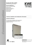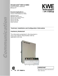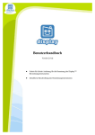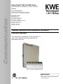
1
Versatronik® 532 & 532D Solar Communication Gateway for solar controls Modbus Communication Document Applicable to: Versatronik 532 Solar/Modbus P/N 704089 Versatronik 532D Solar/Modbus P/N 704090 Applicable Controls Resol Deltasol M Resol Deltasol BS Plus Resol Deltasol BS1/2/3/4 Resol Deltasol BX/BXL Resol Deltasol E/ES/BX/MX/SKSC3 Viessmann Vitosolic 200 Viessmann SCU 124 Viessmann SCU 224 Viessmann SCU 345 Technical, Installation and Configuration Information Cautionary Statement The information presented in this document is only to be used by those familiar with its application and use. IMPORTANT Read and save these instructions for future reference About these instructions ! Take note of all symbols and notations intended to draw attention to potential hazards or important product information. These include “WARNING”, “CAUTION” and “IMPORTANT”. See below. ! WARNING KWE P/N 394047 Versatronik 532 Solar/Modbus Gateway V1.0 09/2013 Technical information subject to change without notice Indicates an imminently hazardous situation which, if not avoided, could result in death, serious injury or substantial product/property damage. ! CAUTION Indicates an imminently hazardous situation which, if not avoided, may result in minor injury or product/property damage. Warnings draw your attention to the presence of potential hazards or important product information. Cautions draw your attention to the presence of potential hazards or important product information CAUTION Static sensitive components may be damaged by improper handling or work within the control. Ensure all possible measures are taken to eliminate build-up of static electricity. IMPORTANT Trademark Information RESOL® and DeltaSol® M are trademarks of RESOL. For more information please visit www.resol-gmbh.de Viessmann® and Vitotronic® are trademarks of Viessmann Werke GmbH & Co KG registered in the United States and other countries. Please visit: www.viessmann.ca www.viessmann.us 2 Helpful hints for installation, operation or maintenance which pertains to the product. Important Regulatory and Installation Requirements Codes The installation of this unit must be in accordance with local codes. KWE P/N 394047 Versatronik 532 Solar/Modbus Gateway V1.0 09/2013 Technical information subject to change without notice All electrical wiring is to be done in accordance with the latest edition of CSA C22,1 Part 1 and/ or local codes. In the U.S. use the National Electrical Code ANSI/NFPA 70. The installing contractor must comply with the Standard of Controls and Safety Devices for Automatically fired Boilers, ANSI/ ASME CSD-1 where required by the authority having jurisdiction. Working on the equipment The installation, adjustment, service and maintenance of this unit must be done by a licensed professional heating contractor or persons who are qualified and experienced in the installation, service, and maintenance of similar products. There are no user serviceable parts on this control. Power supply Install power supply in accordance with the regulation of the authorities having jurisdiction or in absence of such requirements, in accordance with National Codes. Purpose of Device and Operation The Versatronik 532 Solar gateway provides a communication translation between applicable controls and DDC systems which are capable of Modbus RS485 communications. The Versatronik gateway may be either part of a control panel or stand-alone control device. 3 Please carefully read this manual prior to attempting installation. Any warranty is null and void if these instructions are not followed. The completeness and functionality of field supplied electrical controls and components must be verified by those installing the device ! WARNING More than one live circuit. See wiring diagram in this manual. Turn off power supply to control and damper/blower before servicing. Contact with live electrical components can result in serious injury or death Installation Mounting Versatronik Gateway—120VAC Unit KWE P/N 394047 Versatronik 532 Solar/Modbus Gateway V1.0 09/2013 Technical information subject to change without notice 2 1 4 1 3 Mounting Steps 1. Mount Versatronik 532 Gateway in a convenient location near the solar control. Remove cover by loosening the two screws on either side of base to release the cover. 2. Fasten base to wall using field-supplied screws/fasteners. 3. Remove knockout and installed wire strain relief or box connector. Removal of remaining knockouts is required to make further connections. 4. Once all of the 120VAC and low voltage connections are complete and verified, reinstall the cover from Step 1. ! WARNING When extending wire there is the possibility of exposure to electromagnetic interference. Avoid running wires beside or near high voltage 120/240 VAC conductors. If proximity to high voltage conductors cannot be avoided, use stranded, twisted pair of shield design wire. Ensure that only one end of the shielding is grounded. 4 Installation Mounting Versatronik Gateway—24VAC DIN Rail Unit Mounting Steps 1 2 " ! ! " # BACnet IP connection. Solar Control Connection RJ45 Paralleled BUS connection LON connection terminals A and B 24VAC Power Connection 1. 2. 3. 4. 5. Connection Overview 4 3 1 KWE P/N 394047 Versatronik 532 Solar/Modbus Gateway V1.0 09/2013 Technical information subject to change without notice 1. Mount Versatronik 532d Gateway onto DIN rail within an enclosure in a convenient location near the solar control. 2. Make all the necessary connections including the 24VAC power connection. ! ! 5 WARNING When extending wire there is the possibility of exposure to electromagnetic interference. Avoid running wires beside or near high voltage 120/240 VAC conductors. If proximity to high voltage conductors cannot be avoided, use stranded, twisted pair of shield design wire. Ensure that only one end of the shielding is grounded. 5 Connection Overview RJ45 Communication Cable Supplied Connection Overview KWE P/N 394047 Versatronik 532 Solar/Modbus Gateway V1.0 09/2013 Technical information subject to change without notice 1. Cut UTP cable to 2m length. 2. Strip insulation and crimp plug on one end. 3. Strip other end, cut all wires but wire 1 and 2. 4. Strip wire 1 and 2. 5. Wires 1 and 2 used to make connections to the solar control. 6 Versatronik 532 Dial Setting Overview Rotary Dial Setting Setting Overview 1. The rotary dial setting on the Versatronik Gateways provides addressing information for systems that may utilize a number of Versatronik Gateways. Applications with the Versatronik 532 Solar with RESOL controls, it is not required to make adjustments to the rotary dial setting. It should be left in the factory default position setting of 0. + #$ % % ( ( ( ) * ( + & & !" & ' KWE P/N 394047 Versatronik 532 Solar/Modbus Gateway V1.0 09/2013 Technical information subject to change without notice 1 7 Connection Overview—120VAC Unit MODBUS Communication connections to BMS: Example: Resol Deltasol BS Plus Connection Overview 1 Control sensor portion of control. 1 2 A CAT-5 cable is supplied with the Versatronik Solar Gateway. The RJ45 is plugged into the gateway and terminates into the control. 4 Standard plug-in power connection supply for the gateway. It requires 120VAC for its operation. 2 BMS Connection 3 + #$ % % ) ( ( ( * ( + & & !" & ' KWE P/N 394047 Versatronik 532 Solar/Modbus Gateway V1.0 09/2013 Technical information subject to change without notice 3 BMS connection. 4 120VAC 8 Connection Overview—120VAC Unit MODBUS Communication Connections to BMS: Example: Resol Deltasol M Connection Overview 1 Control sensor portion of control. V Bus 1 2 A CAT-5 cable is supplied with the Versatronik Solar Gateway. The RJ45 is plugged into the gateway and terminates into the control. 4 Standard plug-in power connection supply for the gateway. It requires 120VAC for its operation. BMS Connection 2 3 + #$ % % ) ( ( ( * ( + & & !" & ' KWE P/N 394047 Versatronik 532 Solar/Modbus Gateway V1.0 09/2013 Technical information subject to change without notice 3 BMS connection. 4 120VAC 9 Connection Overview—24VAC DIN Rail Unit MODBUS Communication Connections to BMS: Example: Resol Deltasol BS Plus Connection Overview 1 Control sensor portion of control. 1 2 A CAT-5 cable is supplied with the Versatronik Solar Gateway. The RJ45 is plugged into the gateway and terminates into the control. 4 Standard plug-in power connection supply for the gateway. It requires 24VAC for its operation. 2 BMS Connection 3 " ! " # ! KWE P/N 394047 Versatronik 532 Solar/Modbus Gateway V1.0 09/2013 Technical information subject to change without notice 3 BMS connection. ! 4 24VAC 10 Connection Overview—24VAC DIN Rail Unit MODBUS Communication Connections to BMS: Example: Resol Deltasol M Connection Overview 1 Control sensor portion of control. 2 A CAT-5 cable is supplied with the Versatronik Solar Gateway. The RJ45 is plugged into the gateway and terminates into the control. V Bus 1 4 Standard plug-in power connection supply for the gateway. It requires 24VAC for its operation. 2 BMS Connection 3 " ! # ! " KWE P/N 394047 Versatronik 532 Solar/Modbus Gateway V1.0 09/2013 Technical information subject to change without notice 3 BMS connection. 4 24VAC 11 ! Modbus Information Overview: Wiring RS-485 Network COM1 terminals A and B are used. The A and B naming convention may differ across manufacturers. Refer to individual wiring/installation pages in this manual. KWE P/N 394047 Versatronik 532 Solar/Modbus Gateway V1.0 09/2013 Technical information subject to change without notice A=(+) non-inverting B=(—) inverting Termination and Bias This device does not have a termination resistor installed There are two 4.7kohm pull up/down resistors located on the lines to maintain bias. LED Operation LED2 will blink every time a Modbus request is seen on the network Modbus Communication Configuration Settings The gateway is a Modbus slave and all communication has to be initiated by a master. To set up successful communication with the gateway all connection parameters have to be set correctly to the following: 9600 8-N-1 RTU. Mode RTU Baud Rate 9600bps Data Bits/Length 8 Parity None Stop bits 1 Address/Device ID 88, 1-9 Trouble-Shooting Problem: Not getting a response from the gateway device 12 Ensure the connection is set to 9600 8-N-1 Check the rotary dial switch for the device addressing and it not in between dial settings Ensure the communication cables match their polarity Deltasol BS1/2/3/4 Deltasol-E Deltasol-ES Controls temperature units1 - X X X X X X Discrete Inputs 10001-10016 Sensor 1-16 Open Error Binary X - - - - - Discrete Inputs 10017-10032 Sensor 1-16 Shorted Error Binary X - - - KWE P/N 394047 Versatronik 532 Solar/Modbus Gateway V1.0 09/2013 Technical information subject to change without notice - X X X - X - - X Discrete Inputs 10033-10048 Sensor 1-16 Connected Binary X - X - - - - Discrete Inputs 10049-10064 Relay Flags 1-16 Binary X X - - X - - - Discrete Inputs 10065-10080 Error Flags 1-16 Binary X X X X - X X X X6 Discrete Inputs 10080-10096 Warning Flags 1-16 Binary X - - - - - - - - Input Register 30001 Temperature Sensor 1 C or F X X X X X X X X X Input Register 30002 Temperature Sensor 2 C or F X X X X X X X X X Input Register 30003 Temperature Sensor 3 C or F X X X X X X X X X Input Register 30004 Temperature Sensor 4 C or F X X X X X X X X X Input Register 30005 Temperature Sensor 5 C or F X - - X X X X X X Input Register 30006 Temperature Sensor 6 C or F X - - X X - X X X Input Register 30007 Temperature Sensor 7 C or F X - - X X - X X X Input Register 30008 Temperature Sensor 8 C or F X - - X X - X X X Input Register 30009 Temperature Sensor 9 C or F X - - X - - X X - Input Register 30010 Temperature Sensor 10 C or F X - - X - - X X - Input Register 30011 Temperature Sensor 11 C or F X - - - - - X X - Input Register 30012 Temperature Sensor 12 C or F X - - - - - X X - Input Register 30013 Irradiation W/m2, W/ft2 X - - X X - X X Input Register 30014 Pulse Counter 1 - X - - X - - - - Input Register 30015 Pulse Counter 2 - X - - - - - - - Input Register 30016 Speed Relay 1 % X X X X X X X X X Input Register 30017 Speed Relay 2 % X X X X X X X X X Input Register 30018 Speed Relay 3 % X - - X X X X X X Input Register 30019 Speed Relay 4 % X - - X - X X X X Input Register 30020 Speed Relay 5 % X - - X - - X X - Input Register 30021 Speed Relay 6 % X - - X - - X - Input Register 30022 Speed Relay 7 % X - - X - - X - Input Register 30023 Speed Relay 8 % X - - - - - X - Input Register 30024 Speed Relay 9 % X - - - - - X - Input Register 30025 Speed Relay 10 % X - - - - - X - 7 X - 7 X - Input Register 30026 Input Register 30027 Speed Relay 11 Speed Relay 12 % % - Superscript references please refer to following page 13 - - Deltasol-SKSC3 SCU224, SCU124, Deltasol BS Plus Coil Register 97 Deltasol-MX Units See following page for configuration notes Deltasol BX Plus Description VBus Modbus Objects Deltasol-BX Deltasol-BXL/SCU345 Object Deltasol-M, Vitosolic 200 Modbus Information - - - X X Modbus Information SCU224, SCU124, Deltasol BS Plus Deltasol BS1/2/3/4 Deltasol-E Deltasol-MX Deltasol-SKSC3 Binary or Dec. - X3 - X5 X3 - - - Input Register 30029 Heat Quantity in Wh4 Wh - X X - X X - X KWE P/N 394047 Versatronik 532 Solar/Modbus Gateway V1.0 09/2013 Technical information subject to change without notice Deltasol BX Plus Units Option Mask / Schema Deltasol-BX Deltasol-BXL/SCU345 Description Input Register 30028 See below for configuration notes Deltasol-ES Object Deltasol-M, Vitosolic 200 VBus Modbus Objects Continued Input Register 30030 Heat Quantity in kWh4 kWh - X X - X X - X Input Register 30031 Heat Quantity in MWh4 MWh - X X - X X - X Input Register 30032 Operating Hours 1 Hours - X X - X X - - Input Register 30033 Operating Hours 2 Hours - X X - X X - - Input Register 30034 Operating Hours 3 Hours - - - - X X - - Input Register 30035 Operating Hours 4 Hours - - - - X X - - Input Register 30036 Operating Hours 5 Hours - - - - X - - - Input Register 30037 Operating Hours 6 Hours - - - - X - - - Input Register 30038 Zone Supply 1 C or F - - - X - - - - Input Register 30039 Zone Supply 2 C or F - - - X - - - - Input Register 30040 Zone Supply 3 C or F - - - X - - - - Input Register 30041 Zone Supply 4 C or F - - - X - - - - Input Register 30042 Zone Status 1 - - - X - - - - Input Register 30043 Zone Status 2 - - - X - - - - Input Register 30044 Zone Status 3 - - - X - - - - Input Register 30045 Zone Status 4 - - - X - - - - Input Register 30046 Flow Volume (VFS) - - - X X - X l/h or gpm X Configuration Notes Note 1: All input/holding registers are signed 16-bit integers with a multiplier of 1 Note 2: Depending on your unit, and the unit settings, it will transmit the values in Celsius or Fahrenheit. 2 Convert to binary Bit 0: Sensor/Relay 1 (least significant bit, furthest to the right) Bit 1: Sensor/Relay 2 3 Convert to binary: Bit 0: Collector cooling, collector 1 (OCX) Bit 1: Minimum limitation, collector 1 (OCN) Bit 2: Antifreeze, collector 1 (OCF) Bit 3: Tube collector special function (OTC) Bit 4: Re-cooling function (OREC) Bit 5: Heat quantity measurement (OHQM) 4 Values roll over when reaching the next base-1000 magnitude (i.e. 999 Wh becomes 0 Wh + 1 KWh.) 5 System Arrangement 6 Warning Flags: Flag 1: Broken sensor Flag 2: Short circuit sensor Flag 3: DT high Flag 4: Warning circulation at night 7 Speed Pulse Width Modulation (PWM) 1,2 14 Technical Information 3 7 8 + + #$ 9 % % ) ( ( ( * ( 6 & & & ' KWE P/N 394047 Versatronik 532 Solar/Modbus Gateway V1.0 09/2013 Technical information subject to change without notice 5 !" 10 4 2 1 PCB Identifiers Specifications 1 120VAC Power Supply Connections Voltage Requirements 120VAC 2 Fuse Fuse Rating 160mA Time Delay 3 Service Button Power 4VA 4 LON Connections to BMS 5 RJ45 Connection to BMS BACnet Communication Connections Supplied cable between devices 6 Addressing selector for multiple modules 7 COM3 for multiple BUS connections 8 COM4 RJ45 Connection to control 9 Power LED indicator CAUTION Static sensitive components may be damaged by improper handling or work within the control. Ensure all possible measures are taken to eliminate build-up of static electricity. 10 Service LED 15 Technical Information 4 6 7 " ! # ! " KWE P/N 394047 Versatronik 532 Solar/Modbus Gateway V1.0 09/2013 Technical information subject to change without notice 9 8 2 5 3 ! 1 PCB Identifiers Specifications 1 24VAC Power Supply Connections Voltage Requirements 24VAC 2 Power LED indicator Fuse Rating N/A 3 BACnet RJ45 BMS Connection Power 4VA 4 Addressing dial for multiple units 5 COM4 RJ45 Connection to control Communication Connections Supplied cable between devices 6 COM3 for multiple BUS connections 7 Service button 8 Service LED 9 LON Connections to BMS CAUTION Static sensitive components may be damaged by improper handling or work within the control. Ensure all possible measures are taken to eliminate build-up of static electricity. 16 KWE P/N 394047 Versatronik 532 Solar/Modbus Gateway V1.0 09/2013 Technical information subject to change without notice Notes: 17 KWE P/N 394047 Versatronik 532 Solar/Modbus Gateway V1.0 09/2013 Technical information subject to change without notice KWE Technologies Group 750 McMurray Road Waterloo, Ontario, Canada N2V 2G5 Tel: (519) 747-5042 Fax: (519) 747-4448 www.kwe-tech.com [email protected] 18