1
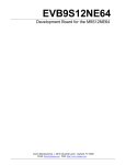
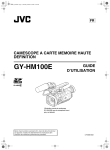
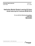
MC68EVB912DP256UM/D Rev 1
December 2000
M68EVB912DP256
EVALUATION BOARD
USER’S MANUAL
Important Notice to Users
While every effort has been made to ensure the accuracy of all information in
this document, Motorola assumes no liability to any party for any loss or
damage caused by errors or omissions or by statements of any kind in this
document, its updates, supplements, or special editions, whether such errors are
omissions or statements resulting from negligence, accident, or any other cause.
Motorola further assumes no liability arising out of the application or use of any
information, product, or system described herein: nor any liability for incidental
or consequential damages arising from the use of this document. Motorola
disclaims all warranties regarding the information contained herein, whether
expressed, implied, or statutory, including implied warranties of
merchantability or fitness for a particular purpose. Motorola makes no
representation that the interconnection of products in the manner described
herein will not infringe on existing or future patent rights, nor do the
descriptions contained herein imply the granting or license to make, use or sell
equipment constructed in accordance with this description.
Trademarks
This document includes these trademarks:
Motorola and the Motorola logo are registered trademarks
of Motorola, Inc.
MCUez is a trademark of Motorola, Inc.
Apple, Macintosh, MacTerminal, and System 7 are registered
trademarks of Apple Computer, Inc.
Windows and Windows 95 are registered trademarks of Microsoft
Corporation in the U.S. and other countries.
Intel is a registered trademark of Intel Corporation.
Sun is a registered trademark of Sun Microsystems, Inc., in the United
States and other countries.
Motorola, Inc., is an Equal Opportunity / Affirmative Action Employer.
© Motorola, Inc., 2000; All Rights Reserved
Contents
Section 1. General Information
1.1
Introduction. . . . . . . . . . . . . . . . . . . . . . . . . . . . . . . . . . . . . . . . . . . . . . 9
1.2
General Description and Features. . . . . . . . . . . . . . . . . . . . . . . . . . . . . 9
1.3
Functional Overview. . . . . . . . . . . . . . . . . . . . . . . . . . . . . . . . . . . . . . 13
1.4
External Equipment Requirements . . . . . . . . . . . . . . . . . . . . . . . . . . . 14
1.5
EVB Specifications. . . . . . . . . . . . . . . . . . . . . . . . . . . . . . . . . . . . . . . 15
1.6
Customer Support . . . . . . . . . . . . . . . . . . . . . . . . . . . . . . . . . . . . . . . . 15
Section 2. Configuration and Setup
2.1
Unpacking and Preparation. . . . . . . . . . . . . . . . . . . . . . . . . . . . . . . . . 17
2.2
EVB Configuration . . . . . . . . . . . . . . . . . . . . . . . . . . . . . . . . . . . . . . . 17
2.3
EVB to Power Supply Connection . . . . . . . . . . . . . . . . . . . . . . . . . . . 18
2.4
EVB to Host Debug Connection. . . . . . . . . . . . . . . . . . . . . . . . . . . . . 18
2.5
EVB to Terminal Connection . . . . . . . . . . . . . . . . . . . . . . . . . . . . . . . 18
Section 3. Operation
3.1
Operating Mode . . . . . . . . . . . . . . . . . . . . . . . . . . . . . . . . . . . . . . . . . 21
3.2
3.2.1
3.2.2
Startup . . . . . . . . . . . . . . . . . . . . . . . . . . . . . . . . . . . . . . . . . . . . . . . . . 21
Startup Procedure . . . . . . . . . . . . . . . . . . . . . . . . . . . . . . . . . . . . . . 21
Operating Procedure . . . . . . . . . . . . . . . . . . . . . . . . . . . . . . . . . . . 22
3.3
Reset . . . . . . . . . . . . . . . . . . . . . . . . . . . . . . . . . . . . . . . . . . . . . . . . . . 22
3.4
Aborting a User Program . . . . . . . . . . . . . . . . . . . . . . . . . . . . . . . . . . 22
3.5
Off-Board Code Generation . . . . . . . . . . . . . . . . . . . . . . . . . . . . . . . . 23
3.6
3.6.1
3.6.2
Memory Usage. . . . . . . . . . . . . . . . . . . . . . . . . . . . . . . . . . . . . . . . . . 23
Description . . . . . . . . . . . . . . . . . . . . . . . . . . . . . . . . . . . . . . . . . . . 23
Memory Map . . . . . . . . . . . . . . . . . . . . . . . . . . . . . . . . . . . . . . . . . 23
MC68EVB912DP256 Evaluation Board
MOTOROLA
User’s Manual
3
Contents
3.7
3.7.1
3.7.2
3.7.3
Operational Limitations . . . . . . . . . . . . . . . . . . . . . . . . . . . . . . . . . . . 24
SCI Port Usage. . . . . . . . . . . . . . . . . . . . . . . . . . . . . . . . . . . . . . . . 24
Dedicated MCU Pins . . . . . . . . . . . . . . . . . . . . . . . . . . . . . . . . . . . 24
Terminal Communications. . . . . . . . . . . . . . . . . . . . . . . . . . . . . . . 25
Section 4. Hardware Reference
4.1
Printed Circuit Board (PCB) Description . . . . . . . . . . . . . . . . . . . . . . 27
4.2
Configuration Headers and Jumper Settings . . . . . . . . . . . . . . . . . . . 27
4.3
Power Input Circuitry . . . . . . . . . . . . . . . . . . . . . . . . . . . . . . . . . . . . . 34
4.4
Terminal Interface. . . . . . . . . . . . . . . . . . . . . . . . . . . . . . . . . . . . . . . . 34
4.5
Microcontroller . . . . . . . . . . . . . . . . . . . . . . . . . . . . . . . . . . . . . . . . . . 35
4.6
Clock Circuitry . . . . . . . . . . . . . . . . . . . . . . . . . . . . . . . . . . . . . . . . . . 37
4.7
Reset . . . . . . . . . . . . . . . . . . . . . . . . . . . . . . . . . . . . . . . . . . . . . . . . . . 37
4.8
Low-Voltage Inhibit (LVI) . . . . . . . . . . . . . . . . . . . . . . . . . . . . . . . . . 37
4.9
Background Debug Mode (BDM) Interface . . . . . . . . . . . . . . . . . . . . 38
4.10
Prototype Area . . . . . . . . . . . . . . . . . . . . . . . . . . . . . . . . . . . . . . . . . . 38
4.11
MCU Connectors . . . . . . . . . . . . . . . . . . . . . . . . . . . . . . . . . . . . . . . . 39
Appendix A. S-Record Format
A.1
Overview. . . . . . . . . . . . . . . . . . . . . . . . . . . . . . . . . . . . . . . . . . . . . . . 45
A.2
S-Record Contents . . . . . . . . . . . . . . . . . . . . . . . . . . . . . . . . . . . . . . . 45
A.3
S-Record Types. . . . . . . . . . . . . . . . . . . . . . . . . . . . . . . . . . . . . . . . . . 46
A.4
S Record Creation . . . . . . . . . . . . . . . . . . . . . . . . . . . . . . . . . . . . . . . . 47
A.5
S-Record Example . . . . . . . . . . . . . . . . . . . . . . . . . . . . . . . . . . . . . . . 47
A.5.1
S0 Header Record . . . . . . . . . . . . . . . . . . . . . . . . . . . . . . . . . . . . . 48
A.5.2
First S1 Record. . . . . . . . . . . . . . . . . . . . . . . . . . . . . . . . . . . . . . . . 49
A.5.3
S9 Termination Record . . . . . . . . . . . . . . . . . . . . . . . . . . . . . . . . . 50
A.5.4
ASCII Characters . . . . . . . . . . . . . . . . . . . . . . . . . . . . . . . . . . . . . . 50
User’s Manual
4
MC68EVB912DP256 Evaluation Board
MOTOROLA
Figures
1-1
1-2
4-1
4-2
4-3
4-4
4-5
. EVB Layout and Component Placement . . . . . . . . . . . . . . . . . . . . . 11
. EVB Solder Side View . . . . . . . . . . . . . . . . . . . . . . . . . . . . . . . . . . . 12
. MCU I/O Headers H1 and H2 . . . . . . . . . . . . . . . . . . . . . . . . . . . . . 39
. MCU I/O Headers H3 and H4 . . . . . . . . . . . . . . . . . . . . . . . . . . . . . 40
. MCU I/O Headers JP1, JP2, and JP3 . . . . . . . . . . . . . . . . . . . . . . . . 41
. MCU I/O Headers JP4, JP5, and JP6 . . . . . . . . . . . . . . . . . . . . . . . . 42
. MCU I/O Headers JP7 and JP8. . . . . . . . . . . . . . . . . . . . . . . . . . . . . 43
MC68EVB912DP256 Evaluation Board
MOTOROLA
User’s Manual
5
Figures
User’s Manual
6
MC68EVB912DP256 Evaluation Board
MOTOROLA
Tables
1-1
2-1
3-1
4-1
4-2
4-3
A-1
A-2
A-3
A-4
A-5
A-6
EVB Specifications. . . . . . . . . . . . . . . . . . . . . . . . . . . . . . . . . . . . . . . 15
RS-232C Interface Cabling. . . . . . . . . . . . . . . . . . . . . . . . . . . . . . . . . 19
Factory-Configuration Memory Map . . . . . . . . . . . . . . . . . . . . . . . . . 23
Jumper-Selectable Functions . . . . . . . . . . . . . . . . . . . . . . . . . . . . . . . 29
CPU Mode Selection . . . . . . . . . . . . . . . . . . . . . . . . . . . . . . . . . . . . . 36
BDM Connector J5 Pin Assignments . . . . . . . . . . . . . . . . . . . . . . . . . 38
S-Record Fields. . . . . . . . . . . . . . . . . . . . . . . . . . . . . . . . . . . . . . . . . . 45
S-Record Field Contents . . . . . . . . . . . . . . . . . . . . . . . . . . . . . . . . . . . 46
S-Record Types. . . . . . . . . . . . . . . . . . . . . . . . . . . . . . . . . . . . . . . . . . 47
S0 Header Record . . . . . . . . . . . . . . . . . . . . . . . . . . . . . . . . . . . . . . . . 48
S1 Header Record . . . . . . . . . . . . . . . . . . . . . . . . . . . . . . . . . . . . . . . . 49
S9 Header Record . . . . . . . . . . . . . . . . . . . . . . . . . . . . . . . . . . . . . . . . 50
MC68EVB912DP256 Evaluation Board
MOTOROLA
User’s Manual
7
Tables
User’s Manual
8
MC68EVB912DP256 Evaluation Board
MOTOROLA
User’s Manual — MC68EVB912DP256 Evaluation Board
Section 1. General Information
1.1 Introduction
This user’s manual provides the necessary information for using the
M68EVB912DP256 evaluation board (EVB), an evaluation, debugging, and
code-generation tool for the MC9S12DP256 microcontroller unit (MCU).
Reference items, such as schematic diagrams and parts lists, are shipped as part
of the EVB package.
1.2 General Description and Features
The EVB is an economical tool for designing and debugging code for and
evaluating the operation of the MC9S12DP256 MCU. By providing the
essential MCU support and input/output (I/O) circuitry, the EVB simplifies user
evaluation of prototype hardware and software.
The board consists of a 9.0-inch by 4.5-inch (22.9-cm by 11.4-cm) four-layer
printed circuit board (PCB) that provides the platform for interface and power
connections to the MC9S12DP256 MCU chip.
Figure 1-1 shows the EVB’s layout and locations of the major components, as
viewed from the component side of the board.
Hardware features of the low-cost EVB include:
•
Four-layer PCB
•
Single-supply +12 Vdc power input
•
RS-232C interface
•
BDM (background debug mode) in and BDM out connectors for remote
debugging of a user’s target system
•
Header footprints for access to all MCU pins
MC68EVB912DP256UM/D Rev 1
MOTOROLA
User’s Manual
General Information
9
General Information
•
16-MHz resonator for 8-MHz bus operation
•
Headers for jumper selection of and connection to hardware options (for
full details of the jumper settings, refer to Table 4-1):
–
RS-232 selection (J6, J7, J10, J12, and J13)
–
EVB mode selection (J20, J24)
–
MCU mode selection (J33, J34, and J25)
–
Power Input (J23)
–
BDM in (J19)
–
BDM out (J22)
–
Low-voltage inhibit (LVI) reset (J14)
–
EXTAL source and access (J26)
•
Twelve 2-row x 14-pin header connectors for access to the MCU’s I/O
and bus lines (H1through H4 and JP1 through JP8)
•
Prototype expansion area for customized interfacing with the MCU
•
Low-profile reset push-button switch (S1)
•
LVI protection (U5)
User’s Manual
10
MC68EVB912DP256UM/D Rev 1
General Information
MOTOROLA
General Information
General Description and Features
Figure 1-1. EVB Layout and Component Placement
MC68EVB912DP256UM/D Rev 1
MOTOROLA
User’s Manual
General Information
11
General Information
Figure 1-2. EVB Solder Side View
User’s Manual
12
MC68EVB912DP256UM/D Rev 1
General Information
MOTOROLA
General Information
Functional Overview
1.3 Functional Overview
The EVB can be configured to:
•
Run a program directly out of EEPROM
•
Reprogram EEPROM on the host EVB
For the correct jumper settings, refer to 4.2 Configuration Headers and
Jumper Settings.
NOTE:
EEPROM resides in two areas of memory (refer to Table 3-1.
Factory-Configuration Memory Map), which are referred to in this manual as
byte-erasable EEPROM and FLASH EEPROM. This distinction is necessary
because of the different ways in which they may be programmed and used.
If the MCU’s single-wire background debug mode (BDM) interface serves as
the user interface, the SCI port becomes available for user applications. This
mode requires either:
•
Another EVB (such as M68EVB912B32) and a host computer
•
A background debug development tool, such as Motorola’s serial debug
interface (SDI)
For more information, refer to the SDI™ Interface User’s Manual, Motorola
document order number SDIUM/D.
Two methods may be used to generate EVB user code:
•
For small programs or subroutines, the BDM interface may be used to
modify memory and place object code directly into the EVB’s RAM or
EEPROM.
•
For larger programs, HiWare’s Panta Tools, P&E Microcomputer
Systems’ IASM12 or Motorola’s MCUasm assembler may be used on a
host computer to generate S-record object files, which then can be loaded
into the EVB’s memory using the BDM interface.
The EVB features a prototype area, which allows custom interfacing with the
MCU’s I/O and bus lines. These connections are broken out via headers
H1through H4, which are immediately adjacent to the MCU on the board, and
JP1 through JP8, which surround jumpers H1 through H4. Wire-wrap pins are
MC68EVB912DP256UM/D Rev 1
MOTOROLA
User’s Manual
General Information
13
General Information
placed in these headers to connect to the prototyping area, as shown in
Figure 1-1.
An on-board push-button switch, S1, provides for resetting the EVB hardware
and restarting any code stored in the MCU’s flash memory.
When operating in EVB mode, the MCU must manage the EVB hardware and
serve as the user-application processor. There are a few restrictions on its use.
For more information, refer to 3.7 Operational Limitations.
1.4 External Equipment Requirements
In addition to the EVB, the following user-supplied external equipment is
required:
•
Power supply — See Table 1-1 for voltage and current requirements.
•
User terminal — Options:
•
–
RS-232C dumb terminal — may be used by user-code
–
Host computer using the MCU’s BDM interface — Frees the target
MCU’s SCI port for user applications. This requires another EVB for
use as the target or a background debug development tool, such as the
Motorola serial debug interface (SDI).
Power-supply and terminal interconnection cables as required
For full details of equipment setup, cabling, and special requirements, refer to
Section 2. Configuration and Setup.
User’s Manual
14
MC68EVB912DP256UM/D Rev 1
General Information
MOTOROLA
General Information
EVB Specifications
1.5 EVB Specifications
Table 1-1 lists the EVB specifications.
Table 1-1. EVB Specifications
Characteristic
Specifications
MCU
MC9S12DP256
MCU I/O ports
HCMOS compatible
BDM (in and out)
2-row x 3-pin headers
Communications port
RS-232C DCE port
Power requirements:
16-MHz clock source
+12 Vdc @ 200 mA (max.)
For low-voltage operation, refer to 4.8 Low-Voltage Inhibit (LVI)
Prototype area:
Area
Holes
20 x 42 Approximately
840 Approximately
Board dimensions
9.0 inches x 4.5 inches (22.9 cm x 11.4 cm)
1.6 Customer Support
To obtain information about technical support or ordering parts, call the
Motorola help desk at 800-521-6274.
MC68EVB912DP256UM/D Rev 1
MOTOROLA
User’s Manual
General Information
15
General Information
User’s Manual
16
MC68EVB912DP256UM/D Rev 1
General Information
MOTOROLA
User’s Manual — MC68EVB912DP256 Evaluation Board
Section 2. Configuration and Setup
2.1 Unpacking and Preparation
Before beginning configuration and setup of the EVB:
1. Verify that these items are present in the EVB package:
•
M68EVB912DP256 board assembly
•
Documentation CD ROM
•
Warranty and registration cards
•
EVB schematic diagram and parts list
•
Assembly language development toolset
•
PANTA tools CD ROM
•
P&E Microcomputer Systems’ IASM12 assembler and user’s
manual on CD ROM (optional)
2. Remove the EVB from its anti-static shipping bag.
3. Save all packing materials for storing and shipping the EVB.
2.2 EVB Configuration
Because the EVB has been factory-configured it is not necessary to change any
of the jumper settings to begin operating immediately.
Other jumper settings affect the hardware setup and/or MCU operational
modes. For an overview of all jumper-selectable functions, refer to 1.2 General
Description and Features. For details of the settings, see Table 4-1.
Jumper-Selectable Functions.
MC68EVB912DP256UM/D Rev 1
MOTOROLA
User’s Manual
Configuration and Setup
17
Configuration and Setup
2.3 EVB to Power Supply Connection
The EVB requires the provided power supply. See Table 1-1. EVB
Specifications for the voltage and current specifications. For full details of the
EVB’s power-input circuitry, refer to 4.3 Power Input Circuitry.
If another power supply is used, it should have current-limiting capability. If
this feature is available on the power supply, set it at 200 mA. The power supply
should use a 2.1 mm ID, 2.5mm OD, 11mm barrel length, and a center-positive
power plug.
Optionally, the +12V DC power may be supplied through J23 terminals +12V
and GND. Under normal operating conditions, the +5V terminal should not be
used. To connect an external power supply through J23, use 20 AWG or smaller
insulated wire. Strip each wire’s insulation 1/4 inch from the end, lift the J23
contact lever to release tension on the contact, insert the bare end of the wire into
J23, and close the lever to secure the wire. Observe the polarity carefully.
CAUTION:
Do not use wire larger than 20 AWG in connector P1. Larger wire could
damage the connector.
2.4 EVB to Host Debug Connection
The MCU’s background debug mode (BDM in, W12) interface serves as the
user interface. This setup makes the SCI port available for user applications.
Additional hardware and software are required. For more information, refer to
the documentation for the background debug development tool being used. This
can be another EVB or a tool such as Motorola’s serial debug interface (SDI).
2.5 EVB to Terminal Connection
For user-code that uses the RS-232 port, connect the terminal to P1 on the EVB,
as shown in Table 2-1. This setup uses the MCU’s SCI port and its associated
RS-232C interface for communications with the terminal device.
Standard, commercially available cables may be used in most cases. Note that
the EVB uses only three of the RS-232C signals. Table 2-1 lists these signals
and their pin assignments. Other signals have been routed through the RS-232C
User’s Manual
18
MC68EVB912DP256UM/D Rev 1
Configuration and Setup
MOTOROLA
Configuration and Setup
EVB to Terminal Connection
interface chip for proper levels. Some terminal interface programs require
proper levels on all pins to function correctly.
The EVB’s RS-232C connector, P1, is wired as data circuit-terminating
equipment (DCE) and employs a 9-pin subminiature D (DB-9) receptacle.
Most terminal devices — whether dumb terminals or the serial ports on host
computers — are wired as data terminal equipment (DTE) and employ 9- or
25-pin subminiature D (DB-9 or DB-25) plugs. In these cases, normal
straight-through cabling is used between the EVB and the terminal. Adapters
are readily available for connecting 9-pin cables to 25-pin terminal connectors.
If the terminal device is wired as DCE, the RXD and TXD lines must be
cross-connected, as shown in Table 2-1. Commercial null modem adapter
cables are available for this purpose.
Table 2-1. RS-232C Interface Cabling
EVB P1
DCE
Receptacle
(1)
(2)
Terminal Pins
DCE(2)
Receptacle
DB-9
DB-25
DB-9
DB-25
2
Receive data (RXD)
2
2
3
3
3
Transmit data (TXD)
3
3
2
2
5
Ground (GND)
5
7
5
7
Normal (DCE-to-DTE) cable connections
Null modem (DCE-to-DCE) cable connections
MC68EVB912DP256UM/D Rev 1
MOTOROLA
DTE(1)
Plug
DTE Signal
User’s Manual
Configuration and Setup
19
Configuration and Setup
User’s Manual
20
MC68EVB912DP256UM/D Rev 1
Configuration and Setup
MOTOROLA
User’s Manual — MC68EVB912DP256 Evaluation Board
Section 3. Operation
3.1 Operating Mode
The EVB operates only in EVB mode. In the EVB mode, user code in FLASH
EEPROM executes and the BDM is enabled.
In the default EVB mode, the user code in FLASH EEPROM begins execution
immediately.
3.2 Startup
To operate the M68EVB912DP256, follow the startup procedure described
here.
3.2.1 Startup Procedure
This startup procedure includes a checklist of configuration and setup items
from Section 2. Configuration and Setup. To begin operating the
M68EVB912DP256, follow these steps:
1. Connect the EVB to the external power supply. See 2.3 EVB to Power
Supply Connection.
2. Connect the EVB to the SDI or equivalent. See 2.4 EVB to Host Debug
Connection.
3. Apply power to the EVB and the host and perform the following steps:
a. Verify that the host has booted correctly.
b. Start the PANTA tools software included on the PANTA tools CD
ROM. See the help files on the PANTA tools CD for more detailed
instructions.
4. Reset the EVB by pressing and releasing the on-board reset switch (S1).
MC68EVB912DP256UM/D Rev 1
MOTOROLA
User’s Manual
Operation
21
Operation
3.2.2 Operating Procedure
After starting the EVB in accordance with 3.2.1 Startup Procedure, follow the
operating procedure for the EVB mode
In EVB mode, the M68EVB912DP256 begins to execute code at the address
contained in the reset vector at $F7FE. The code pointed to by the alternate reset
vector may be a user’s program in FLASH EEPROM.
User boot program — On reset, the user program executes immediately.
Terminal communications take place either via the BDM interface and a serial
debug interface tool such as Motorola’s SDI.
3.3 Reset
EVB operation can be restarted at any time by activating the hardware reset
function. To activate the hardware reset function, press and release the on-board
reset switch, S1 (always applicable).
Note that the EVB’s reset circuitry is associated with the low-voltage inhibit
(LVI) protection. For more information, refer to 4.7 Reset and
4.8 Low-Voltage Inhibit (LVI).
3.4 Aborting a User Program
When operating in EVB mode, the only way to recover from an erroneous or
runaway user program is to press the reset switch (S1).
User’s Manual
22
MC68EVB912DP256UM/D Rev 1
Operation
MOTOROLA
Operation
Off-Board Code Generation
3.5 Off-Board Code Generation
Code developed outside the EVB environment should be generated with an
M68HC12-compatible assembler or C compiler that can generate object files in
S-record format.
S-records are described in Appendix A. S-Record Format.
When the S-record file has been generated, it may be loaded from the host
computer into the host EVB’s byte-erasable EEPROM or RAM when the host
EVB is in EVB mode
More information on the EVB operating mode can be found in 3.1 Operating
Mode.
3.6 Memory Usage
The EVB’s memory usage and requirements are described here and are
summarized in Table 3-1.
3.6.1 Description
To use the FLASH EEPROM area for custom programs, refer to the MCU
specification included on the documentation CD ROM.
3.6.2 Memory Map
The information in Table 3-1 describes address ranges and locations.
Table 3-1. Factory-Configuration Memory Map
Address Range
Usage
Description
$0000 – $03FF
CPU registers
On-chip registers
$1000 – $3FFF
User code/data
12-Kbytes on-chip RAM
$0400 – $0FFF
User code/data
3-Kbytes on-chip EEPROM
$4000 – $FFBF
$FFC0 – $FFFF
User-accessible functions
Reset and interrupt vectors
256 Kbytes on-chip FLASH
EEPROM (accessible through
paging mechanism)
MC68EVB912DP256UM/D Rev 1
MOTOROLA
User’s Manual
Operation
23
Operation
3.7 Operational Limitations
In EVB mode, the EVB cannot provide true emulation of a target system. These
limitations are described in the following subsections.
If target-system emulation is required, the EVB may be reprogrammed and
controlled via the BDM interface.
3.7.1 SCI Port Usage
The SCI port is either connected to the RS-232C RXD and TXD signals for
SCI0 or SCI1 by means of jumpers J12 and J13.
3.7.2 Dedicated MCU Pins
On the EVB, the following MCU lines may be used to perform specific
functions in the future. If an application requires their use, the EVB hardware
and/or operating software must be custom-configured or special precautions
must be taken in the application code to avoid conflicts.
PAD00 — EVB mode select pin (J24)
PAD08 — EVB mode select pin (J20)
MODA (J34) and MODB (J33) — Set MCU chip mode, normally
single chip
User’s Manual
24
MC68EVB912DP256UM/D Rev 1
Operation
MOTOROLA
Operation
Operational Limitations
3.7.3 Terminal Communications
High baud rates occasionally result in dropped characters on the terminal
display. This is not the result of a baud rate mismatch, but is due to the host
processor being too busy or too slow to process incoming data at the selected
baud rate. Sometimes the problem can be ignored without harm.
If it requires correcting, try:
•
Using a slower baud rate
•
A different communications program
•
Closing unnecessary applications or exiting Windows. In multitasking
environments such as Windows® and the Macintosh System 7®, the
problem can occur when several applications are running at once.
•
Displaying fewer address locations or tracing fewer instructions at a
time.
MC68EVB912DP256UM/D Rev 1
MOTOROLA
User’s Manual
Operation
25
Operation
User’s Manual
26
MC68EVB912DP256UM/D Rev 1
Operation
MOTOROLA
User’s Manual — MC68EVB912DP256 Evaluation Board
Section 4. Hardware Reference
4.1 Printed Circuit Board (PCB) Description
The EVB printed circuit board (PCB) is a 9.0-inch by 4.5-inch (22.9-cm
by11.4-cm) board with four layers.
Most of the connection points on the EVB use headers spaced on 1/10-inch
(2.54-mm) centers, with these exceptions:
•
Subminiature D connector for the RS-232C interface
•
External power-supply connections
4.2 Configuration Headers and Jumper Settings
For maximum flexibility, the EVB uses two types of jumper headers:
NOTE:
•
Factory-installed headers are those most likely to be used for
configuration without major alteration of the EVB’s hardware operation.
These headers are populated, and the factory-installed jumpers on them
are preset for the default EVB hardware and firmware configurations.
Table 4-1 lists these headers by function and describes their default and
optional jumper settings.
•
Cut-trace header footprints offer EVB hardware options that are less
likely to be changed. These footprints are often not populated. The
default connection between pins is a trace on the PCB. To change a
cut-trace footprint, the PCB trace must be cut. To return to the original
configuration, a header and a jumper must be installed to re-establish the
shunt.
Use of the cut-trace header footprints requires a thorough understanding of the
MCU and of the EVB hardware. Refer to the MC9S12DP256 Advance
Information, Motorola document order number MC9S12DP256TS/D, and to
the EVB schematic diagram included on the documentation CD ROM for design
information.
MC68EVB912DP256UM/D Rev 1
MOTOROLA
User’s Manual
Hardware Reference
27
Hardware Reference
CAUTION:
When cutting a PCB trace to customize a header footprint, use a sharp blade.
Be careful to avoid personal injury and not to cut adjacent traces.
Key to Table 4-1: Headers are depicted as viewed from either the component
side as shown in Figure 1-1. EVB Layout and Component Placement or
the solder side as shown in Figure 1-2. EVB Solder Side View.
2-pin header with no jumper installed or
2-pin cut-trace header with trace cut
2-pin header with jumper installed
2-pin cut-trace header with default trace intact
1
3-pin header with no jumper installed
1
3-pin header with jumper installed on left 2 pins
1–2
1–2, cut
NOTE:
bold pin numbers indicate factory-default settings
italics indicate alternate settings
J21, J26, and J27 are not used.
User’s Manual
28
MC68EVB912DP256UM/D Rev 1
Hardware Reference
MOTOROLA
Hardware Reference
Configuration Headers and Jumper Settings
Table 4-1. Jumper-Selectable Functions (Sheet 1 of 6)
Diagram
Setting
Description
1–2
2-3
Use on-chip +2.5V regulator
Use external (on-board) regulator - Voltage should be adjusted with
potentiometer R1 and measured at test point TP3 before installation if this
option is used.
1–2
2-3
A-to-D Voltage Reference Low is pulled high (+5Vdc)
VRL is pulled low (0Vdc)
J1 VREGEN
J2 VRL Voltage Select
J3 CAN2 Control Inputs and Outputs
1
3
15-pin jumper used to configure control inputs and outputs for CAN2
interface. See schematics for more detail.
(default - jumper pin 10 to 11 and pin 13 to 14)
13
15
J4 CAN2 Physical Interface Connector
1
2
7
8
1
2
3
4
5
6
7
8
GND
GND
CANH
CANH
CANL
CANL
GND
GND
J5 VRH Voltage Select
1–2
2-3
A-to-D Voltage Reference Low is pulled high (+5Vdc)
VRL is pulled low (0Vdc)
J6 RS232
Connects RS232 DCD to DTR
(default – jumper not installed)
MC68EVB912DP256UM/D Rev 1
MOTOROLA
User’s Manual
Hardware Reference
29
Hardware Reference
Table 4-1. Jumper-Selectable Functions (Sheet 2 of 6)
Diagram
Setting
Description
J7 RS232
Connects RS232 DSR to DTR
(default – jumper not installed)
J8 CAN1 Control Inputs and Outputs
1
3
15-pin jumper used to configure control inputs and outputs for CAN1
interface. See schematics for more detail.
(default - jumper pin 10 to 11 and pin 13 to 14)
13
15
J9 CAN1 Physical Interface Connector
1
2
7
8
1
2
3
4
5
6
7
8
GND
GND
CANH
CANH
CANL
CANL
GND
GND
J10 RS232
Connects RS232 CTS to RTS
(default – jumper not installed)
J11 VCC
1–2
3–4
Cut trace between 1 and 2 and trace between 3 and 4 to measure current
flow on the VDDR, VDDX, and VDDA pins
(default – jumpers not installed)
1–2
2–3
TXD0 to drive RS232 TX
TXD1 to drive RS232 TX
1–2
2–3
RXD0 to drive RS232 RX
RXD1 to drive RS232 RX
J12 RS232
J13 RS232
User’s Manual
30
MC68EVB912DP256UM/D Rev 1
Hardware Reference
MOTOROLA
Hardware Reference
Configuration Headers and Jumper Settings
Table 4-1. Jumper-Selectable Functions (Sheet 3 of 6)
Diagram
Setting
Description
J14 RS232
1–2
2–3
Connects LVI circuit to processor reset pin
Connects Resistor-Capacitor network to processor reset pin
J15 CAN0 Control Inputs and Outputs
1
3
15-pin jumper used to configure control inputs and outputs for CAN0
interface. See schematics for more detail.
(default - jumper pin 10 to 11 and pin 13 to 14)
13
15
J16 CAN0 Physical Interface Connector
1
2
7
8
1
2
3
4
5
6
7
8
GND
GND
CANH
CANH
CANL
CANL
GND
GND
J17 VCC
1–2
2–3
Use +5Vdc on-board regulator
Use off-board +5Vdc supply
J18 SDI Connector
Connector for SDI Connection
See schematics for more details
1
2
3
4
MODA
MODB
GND
PE4
MC68EVB912DP256UM/D Rev 1
MOTOROLA
User’s Manual
Hardware Reference
31
Hardware Reference
Table 4-1. Jumper-Selectable Functions (Sheet 4 of 6)
Diagram
Setting
Description
J19 Background Debugger Connector In
Connector for Background Debug In
1
2
5
6
1
2
3
4
5
6
BKGD
GND
NC
RESeT(L)
NC
VCC (+5V)
J20 PAD08
1–2
2–3
Connects PAD08 to +5Vdc
Connects PAD08 to 0Vdc
(default – jumper not installed)
J22 Background Debugger Connector Out
Connector for Background Debug In
1
2
5
6
1
2
3
4
5
6
PT7
GND
NC
PT6
NC
VCC (+5V)
1
2
3
+12Vdc
GND
+5Vdc
(power is normally supplied via J40, +12Vdc, =200ma, center pin positive)
(default – not used)
J23 Power
J24 PAD00
1–2
2–3
Connects PAD00 to +5Vdc
Connects PAD00 to 0Vdc
(default – jumper not installed)
1–2
2–3
Connects MODC to +5Vdc
Connects MODC to 0Vdc
(default – jumper not installed)
J25 MODC
User’s Manual
32
MC68EVB912DP256UM/D Rev 1
Hardware Reference
MOTOROLA
Hardware Reference
Configuration Headers and Jumper Settings
Table 4-1. Jumper-Selectable Functions (Sheet 5 of 6)
Diagram
Setting
Description
J28 TMOD1
1–2
2–3
Connects TMOD1 to +5Vdc
Connects TMOD1 to 0Vdc
(default – jumper not installed)
J29 LED
Controls LED operation
(default – jumper installed)
J30 TMOD2
1–2
2–3
Connects TMOD2 to +5Vdc
Connects TMOD2 to 0Vdc
(default – jumper not installed)
J31 External Clock Connector
BNC Connector for External Clock
(default – not used)
J32 PE7
1–2
2–3
Connects PE7 to +5Vdc
Connects PE7 to 0Vdc
1–2
2–3
Connects MODB to +5Vdc
Connects MODB to 0Vdc
1–2
2–3
Connects MODA to +5Vdc
Connects MODA to 0Vdc
1–2
2–3
Use on-board oscillator
Use external clock (supplied through J31)
1–2
2–3
Connects TEST to +5Vdc
Connects TEST to 0Vdc
J33 MODB
J34 MODA
J35 Oscillator Selector
J36 TEST
MC68EVB912DP256UM/D Rev 1
MOTOROLA
User’s Manual
Hardware Reference
33
Hardware Reference
Table 4-1. Jumper-Selectable Functions (Sheet 6 of 6)
Diagram
Setting
Description
J37 TERM
Provides 50ohm termination in conjunction with external clock (J35)
(default – jumper not installed)
J38 OSC Enable
Install if using a CMOS/TTL clock oscillator (U9). Remove if using a
discrete crystal unit. (default - installed)
J39 PK7
1-2
2-3
Connects PK7 to +5 VDC
Connects PK7 to Ground
(default - installed)
4.3 Power Input Circuitry
The input power connector on the EVB is a 3-pin, lever-actuated connector
(J23). Decoupling capacitors filter ripple and noise from the supply voltage.
Fuse (F1) is a thermally activated fuse. An overload will cause the fuse to go to
a high impedance state. After power is removed from the board and the fuse
cools, the fuse will change to a low impedance state and permit normal
operation.
4.4 Terminal Interface
An RS-232C transceiver (U1A or U1B) links the MCU’s serial communications
interface to the RS-232C DB-9 receptacle, P1.
User’s Manual
34
MC68EVB912DP256UM/D Rev 1
Hardware Reference
MOTOROLA
Hardware Reference
Microcontroller
4.5 Microcontroller
The MC9S12DP256 is one of the first of a family of next generation M68HC12
microcontrollers with both on-chip memory and peripheral functions. The
CPU12 is a high-speed, 16-bit processing unit. The programming model and
stack frame are identical to those of the standard M68HC11 CPU. The CPU12
instruction set is a proper superset of the M68HC11 instruction set. All
M68HC11 instruction mnemonics are accepted by CPU12 assemblers with no
changes.
The EVB-resident MC9S12DP256 (U2) has seven modes of operation. These
modes are determined at reset by the state of three mode pins — BKGD,
MODB, and MODA — as shown in Table 4-2.
The EVB is factory-configured for MCU operation in the normal single-chip
mode. In this mode of operation, all port pins are available to the user. On-chip
FLASH EEPROM is used for program execution, with byte-erasable EEPROM
and some RAM available for user code/data. Although other MCU modes are
available, the EVB was designed for the single-chip mode of operation. There
is no provision for external memory.
For more information on the CPU, refer to the CPU12 Reference Manual,
Motorola document order number CPU12RM/AD.
MC68EVB912DP256UM/D Rev 1
MOTOROLA
User’s Manual
Hardware Reference
35
Hardware Reference
Table 4-2. CPU Mode Selection
Input
BKGD
& bit
W25
Input
& bit
MODB
W11
Input
&bit
MODA
W10
Mode Description
0
0
0
Special Single Chip, BDM allowed
and ACTIVE. BDM is “allowed” in
all other modes but a serial
command is required to make
BDM “active.”
0
0
1
Emulation Expanded Narrow,
BDM allowed
0
1
0
Special Test (Expanded Wide),
BDM allowed
0
1
1
Emulation Expanded Wide, BDM
allowed
1
0
0
Normal Single Chip, BDM
allowed
1
0
1
Normal Expanded Narrow, BDM
allowed
1
1
0
Peripheral; BDM allowed but bus
operations would cause bus
conflicts (must not be used)
1
1
1
Normal Expanded Wide; BDM
allowed
There are two basic types of operating modes:
•
Normal modes in which some registers and bits are protected against
accidental changes.
•
Special modes that allow more access to protected control registers and
bits for special purposes such as testing.
User’s Manual
36
MC68EVB912DP256UM/D Rev 1
Hardware Reference
MOTOROLA
Hardware Reference
Clock Circuitry
4.6 Clock Circuitry
The EVB comes with a 16-MHz crystal resonator, U9. The board should be able
to accommodate most crystals and oscillators.
Headers J35 and J36 may be used to disconnect the oscillator (U9) or crystal
(Y1) from the MCU’s on-chip oscillator. An external clock may then be
supplied to EXTAL through J31. See the schematics for more detailed
information.
4.7 Reset
The reset circuit includes a pullup resistor, reset switch (S1), and a low-voltage
inhibit device with a toggle voltage of 4.6 Vdc. This reset circuit drives the
MCU’s RESET pin directly. Note that header J14 may be used to provide an
alternate reset input, provided the cut trace is removed.
4.8 Low-Voltage Inhibit (LVI)
Low-voltage inhibit (LVI) uses an undervoltage sensing device (U5) to
automatically drive the MCU’s RESET pin low when VDD falls below U5’s
threshold. This prevents the accidental corruption of EEPROM data if the
power-supply voltage should drop below the allowable level.
U5 may be identified by part number MC34164P-5 — 4.5 Vdc.
If operation below U5’s threshold (but no less than 2.7 Vdc) is required, one of
two methods can be used:
•
Replace U5 with a device that has the required threshold voltage.
•
Remove the shunt J14 to disconnect U5 from the RESET line. If this is
done, an external reset signal should be provided via the center pin of J14
in case the supply voltage falls below the acceptable level.
Optionally, pins 2 and 3 of J14 can be jumpered to provide an RC type
reset function. See the schematic for more detailed information.
MC68EVB912DP256UM/D Rev 1
MOTOROLA
User’s Manual
Hardware Reference
37
Hardware Reference
4.9 Background Debug Mode (BDM) Interface
The MCU’s serial BDM interface can be accessed through two 2-row x 3-pin
headers, BDM in (J19) and BDM out (J22). The pin assignments are shown in
Table 4-3.
The BDM interface may serve in two ways:
•
As the “probe” interface through which a host EVB in pod mode controls
a target system.
•
As the user interface with the EVB. This requires a development tool
such as Motorola’s serial debug interface. For more information, refer to
the SDI™ Interface User’s Manual, Motorola document order number
SDIUM/D.
Table 4-3. BDM Connector J5 Pin Assignments
Description
Pin
Number
(1)
J19 (In)
J22 (Out)
1
BKGD input to MCU
BKGD output from MCU PT7
2
VSS
VSS
3
No connection
No connection
4
RESET input to MCU
RESET output from MCU PT6 (1)
5
No connection
No connection
6
VDD
VDD (1)
Refer to Table 4-1.
4.10 Prototype Area
The EVB’s prototype area allows construction of custom I/O circuitry that can
be connected to the MCU’s I/O lines through connectors JP1 through JP8. This
area is a grid of holes (approximately 20 by 42) on 1/10-inch (2.54 mm) centers.
This spacing accommodates most sockets, headers, and device packages.
Figure 1-1. EVB Layout and Component Placement shows the
component-side view of the prototype area. Adjacent ground and VCC (+5V)
footprints are provided for wire-wrap pins.
User’s Manual
38
MC68EVB912DP256UM/D Rev 1
Hardware Reference
MOTOROLA
Hardware Reference
MCU Connectors
4.11 MCU Connectors
Twelve 2-row x 14-pin header footprints, H1through H4 and JP1 through JP8,
surround the MCU and provide access to its I/O and bus lines. They may be
populated with wire-wrap pins or strip headers for use as I/O connectors,
connection points for instrumentation probes and target hardware, and
connections to the prototype area described in 4.10 Prototype Area. The
following figures depict the pin assignments for these headers.
H1
SS1n/PW3/KWP3/PP3 (P1)
MOSI1/PW1/KWP1/PP1 (P3)
PK3/PIX3 (P5)
PK1/PIX1 (P7)
IOC0/PT0 (P9)
IOC2/PT2 (P11)
VDD1 (P13)
IOC4/PT4 (P15)
IOC6/PT6 (P17)
PK5/PIX5 (P19)
KWJ1/PJ1 (P21)
MODC/TAGHIn/BKGD (P23)
PB1/AD1 (P25)
PB3/AD3 (P27)
1
3
5
7
9
11
13
15
17
19
21
23
25
27
•
•
•
•
•
•
•
•
•
•
•
•
•
•
PB5/AD5 (P29)
PB7/AD7 (P31)
KWH6/PH6 (P33)
KWH4/PH4 (P35)
PE6/MODB/IPIPE1 (P37)
PE4/ECLK (P39)
VDDR (P41)
VDDPLL (P43)
GND
NC
KWH3/PH3 (P49)
KWH1/PH1 (P51)
PE3/LSTRBN/TAGLOn (P53)
PE1/IRQn (P55)
1
3
5
7
9
11
13
15
17
19
21
23
25
27
•
•
•
•
•
•
•
•
•
•
•
•
•
•
•
•
•
•
•
•
•
•
•
•
•
•
•
•
2
4
6
8
10
12
14
16
18
20
22
24
26
28
SCK1/PW2/KWP2/PP2 (P2)
MISO1/PW0/KWP0/PP0 (P4)
PK2/PIX2 (P6)
PK0/PIX0 (P8)
IOC1/PT1 (P10)
IOC3/PT3 (P12)
GND
IOC5/PT5 (P16)
IOC7/PT7 (P18)
PK4/PIX4 (P20)
KWJ0/PJ0 (P22)
PB0/AD0 (P24)
PB2/AD2 (P26)
PB4/AD4 (P28)
2
4
6
8
10
12
14
16
18
20
22
24
26
28
PB6/AD6 (P30)
KWH7/PH7 (P32)
KWH5/PH5 (P34)
PE7/XCLKSn/NOACC (P36)
PE5/MODA/IPIPE0 (P38)
GND
RESETn (P42)
NC (P44)
EXTAL (P46)
TEST (P48)
KWH2/PH2 (P50)
KWH0/PH0 (P52)
PE2/RWn (P54)
PE0/XIRQn (P56)
H2
•
•
•
•
•
•
•
•
•
•
•
•
•
•
Figure 4-1. MCU I/O Headers H1 and H2
MC68EVB912DP256UM/D Rev 1
MOTOROLA
User’s Manual
Hardware Reference
39
Hardware Reference
H3
PA0/AD8 (P57)
PA2/AD10 (P59)
PA4/AD12/TMOD1 (P61)
PA6/AD14/TMOD2 (P63)
VDD2 (P65)
PAD00/AN00 (P67)
PAD01/AN01 (P69)
PAD02/AN02 (P71)
PAD03/AN03 (P73)
PAD04/AN04 (P75)
PAD05/AN05 (P77)
PAD06/AN06 (P79)
PAD07/AN07 (P81)
VDDA (P83)
1
3
5
7
9
11
13
15
17
19
21
23
25
27
•
•
•
•
•
•
•
•
•
•
•
•
•
•
•
•
•
•
•
•
•
•
•
•
•
•
•
•
2
4
6
8
10
12
14
16
18
20
22
24
26
28
PA1/AD9 (P58)
PA3/AD11 (P60)
PA5/AD13 (P62)
PA7/AD15 (P64)
GND
PAD08/AN08 (P68)
PAD09/AN09 (P70)
PAD10/AN10 (P72)
PAD11/AN11 (P74)
PAD12/AN12 (P76)
PAD13/AN13 (P78)
PAD14/AN14 (P80)
PAD15/AN15 (P82)
VRH (P84)
H4
VRL (P85)
PM7/TXCAN3 (P87)
PS0/RXD0 (P89)
PS2/RXD1 (P91)
PS4//SDI/MISO0 (P93)
PS6/SCK0 (P95)
VREGEN (P97)
PJ6/KWJ6/SDA/RXCAN4 (P99)
PM4/RXCAN2 (P101)
PM2/RXCAN1 (P103)
PM0/RXB/RXCAN0 (P105)
VDDX (P107)
SCK2/PW7/KWP7/PP7 (P109)
MOSI2/PW5/KWP5/PP5 (P111)
1
3
5
7
9
11
13
15
17
19
21
23
25
27
•
•
•
•
•
•
•
•
•
•
•
•
•
•
•
•
•
•
•
•
•
•
•
•
•
•
•
•
2
4
6
8
10
12
14
16
18
20
22
24
26
28
GND
PM6/RXCAN3 (P88)
PS1/TXD0 (P90)
PS3/TXD1 (P92)
PS5/MOSI0 (P94)
PS7/SS0n (P96)
PJ7/KWJ7/SCL/TXCAN4 (P98)
PM5/TXCAN2 (P100)
PM3/TXCAN1 (P102)
PM1/TXB/TXCAN0 (P104)
GND
PK7/ECSn (P108)
SS2n/PW6/KWP6/PP6 (P110)
MISO2/PW4/KWP4/PP4 (P112)
Figure 4-2. MCU I/O Headers H3 and H4
User’s Manual
40
MC68EVB912DP256UM/D Rev 1
Hardware Reference
MOTOROLA
Hardware Reference
MCU Connectors
JP1
NC
NC
NC
NC
NC
NC
NC
NC
NC
NC
NC
NC
VADJ
NC
1
3
5
7
9
11
13
15
17
19
21
23
25
27
NC
NC
PT6
PT7
NC
NC
NC
NC
BKGD
PB0
PB1
PB2
PB3
PB4
1
3
5
7
9
11
13
15
17
19
21
23
25
27
PB5
PB6
PB7
PH7
PH6
PH5
PH4
PE7
MODB
MODA
PE4
NC
VDDR
RESETn
1
3
5
7
9
11
13
15
17
19
21
23
25
27
•
•
•
•
•
•
•
•
•
•
•
•
•
•
•
•
•
•
•
•
•
•
•
•
•
•
•
•
2
4
6
8
10
12
14
16
18
20
22
24
26
28
SS1n/PW3/KWP3/PP3 (P1)
SCK1/PW2/KWP2/PP2 (P2)
MOSI1/PW1/KWP1/PP1 (P3)
MISO1/PW0/KWP0/PP0 (P4)
PK3/PIX3 (P5)
PK2/PIX2 (P6)
PK1/PIX1 (P7)
PK0/PIX0 (P8)
IOC0/PT0 (P9)
IOC1/PT1 (P10)
IOC2/PT2 (P11)
IOC3/PT3 (P12)
VDD1 (P13)
NC
2
4
6
8
10
12
14
16
18
20
22
24
26
28
IOC4/PT4 (P15)
IOC5/PT5 (P16)
IOC6/PT6 (P17)
IOC7/PT7 (P18)
PK5/PIX5 (P19)
PK4/PIX4 (P20)
KWJ1/PJ1 (P21)
KWJ0/PJ0 (P22)
MODC/TAGHIn/BKGD (P23)
PB0/AD0 (P24)
PB1/AD1 (P25)
PB2/AD2 (P26)
PB3/AD3 (P27)
PB4/AD4 (P28)
2
4
6
8
10
12
14
16
18
20
22
24
26
28
PB5/AD5 (P29)
PB6/AD6 (P30)
PB7/AD7 (P31)
KWH7/PH7 (P32)
KWH6/PH6 (P33)
KWH5/PH5 (P34)
KWH4/PH4 (P35)
PE7/XCLKSn/NOACC (P36)
PE6/MODB/IPIPE1 (P37)
PE5/MODA/IPIPE0 (P38)
PE4/ECLK (P39)
NC
VDDR (P41)
RESETn (P42)
JP2
•
•
•
•
•
•
•
•
•
•
•
•
•
•
•
•
•
•
•
•
•
•
•
•
•
•
•
•
JP3
•
•
•
•
•
•
•
•
•
•
•
•
•
•
•
•
•
•
•
•
•
•
•
•
•
•
•
•
Figure 4-3. MCU I/O Headers JP1, JP2, and JP3
MC68EVB912DP256UM/D Rev 1
MOTOROLA
User’s Manual
Hardware Reference
41
Hardware Reference
JP4
VADJ
NC
NC
EXTAL
NC
TEST
PH3
PH2
PH1
PH0
NC
NC
NC
NC
1
3
5
7
9
11
13
15
17
19
21
23
25
27
NC
NC
NC
NC
TMOD2
NC
TMOD1
NC
VADJ
NC
PAD00
PAD08
NC
NC
1
3
5
7
9
11
13
15
17
19
21
23
25
27
NC
NC
NC
NC
NC
NC
NC
NC
NC
NC
NC
NC
VDDA
VRH
1
3
5
7
9
11
13
15
17
19
21
23
25
27
•
•
•
•
•
•
•
•
•
•
•
•
•
•
•
•
•
•
•
•
•
•
•
•
•
•
•
•
2
4
6
8
10
12
14
16
18
20
22
24
26
28
VDDPLL (P43)
NC (P44)
NC
EXTAL (P46)
NC
TEST (P48)
KWH3/PH3 (P49)
KWH2/PH2 (P50)
KWH1/PH1 (P51)
KWH0/PH0 (P52)
PE3/LSTRBN/TAGLOn (P53)
PE2/RWn (P54)
PE1/IRQn (P55)
PE0/XIRQn (P56)
2
4
6
8
10
12
14
16
18
20
22
24
26
28
PA0/AD8(P57)
PA1/AD9(P58)
PA2/AD10 (P59)
PA3/AD11 (P60)
PA4/AD12/TMOD1 (P61)
PA5/AD13 (P62)
PA6/AD14/TMOD2 (P63)
PA7/AD15 (P64)
VDD2 (P65)
NC
PAD00/AN00 (P67)
PAD08/AN08 (P68)
PAD01/AN01 (P69)
PAD09/AN09 (P70)
2
4
6
8
10
12
14
16
18
20
22
24
26
28
PAD02/AN02 (P71)
PAD10/AN10 (P72)
PAD03/AN03 (P73)
PAD11/AN11 (P74)
PAD04/AN04 (P75)
PAD12/AN12 (P76)
PAD05/AN05 (P77)
PAD13/AN13 (P78)
PAD06/AN06 (P79)
PAD14/AN14 (P80)
PAD07/AN07 (P81)
PAD15/AN15 (P82)
VDDA (P83)
VRH (P84)
JP5
•
•
•
•
•
•
•
•
•
•
•
•
•
•
•
•
•
•
•
•
•
•
•
•
•
•
•
•
JP6
•
•
•
•
•
•
•
•
•
•
•
•
•
•
•
•
•
•
•
•
•
•
•
•
•
•
•
•
Figure 4-4. MCU I/O Headers JP4, JP5, and JP6
User’s Manual
42
MC68EVB912DP256UM/D Rev 1
Hardware Reference
MOTOROLA
Hardware Reference
MCU Connectors
JP7
VRL
NC
NC
NC
RXD0
TXD0
RXD1
TXD1
NC
NC
NC
NC
VREGEN
VCC
1
3
5
7
9
11
13
15
17
19
21
23
25
27
•
•
•
•
•
•
•
•
•
•
•
•
•
•
•
•
•
•
•
•
•
•
•
•
•
•
•
•
2
4
6
8
10
12
14
16
18
20
22
24
26
28
VRL(P85)
NC
PM7/TXCAN3 (P87)
PM6/RXCAN3 (P88)
PS0/RXD0 (P89)
PS1/TXD0 (P90)
PS2/RXD1 (P91)
PS3/TXD1 (P92)
PS4//SDI/MISO0 (P93)
PS5/MOSI0 (P94)
PS6/SCK0 (P95)
PS7/SS0n (P96)
VREGEN (P97)
PJ7/KWJ7/SCL/TXCAN4 (P98)
JP8
VCC
TXCAN2
RXCAN2
TXCAN1
RXCAN1
TXCAN0
RXCAN0
NC
VDDX
PK7
NC
NC
NC
NC
1
3
5
7
9
11
13
15
17
19
21
23
25
27
•
•
•
•
•
•
•
•
•
•
•
•
•
•
•
•
•
•
•
•
•
•
•
•
•
•
•
•
2
4
6
8
10
12
14
16
18
20
22
24
26
28
PJ6/KWJ6/SDA/RXCAN4 (P99)
PM5/TXCAN2 (P100)
PM4/RXCAN2 (P101)
PM3/TXCAN1 (P102)
PM2/RXCAN1 (P103)
PM1/TXB/TXCAN0 (P104)
PM0/RXB/RXCAN0 (P105)
NC
VDDX (P107)
PK7/ECSn (P108)
SCK2/PW7/KWP7/PP7 (P109)
SS2n/PW6/KWP6/PP6 (P110)
MOSI2/PW5/KWP5/PP5 (P111)
MISO2/PW4/KWP4/PP4 (P112)
Figure 4-5. MCU I/O Headers JP7 and JP8
MC68EVB912DP256UM/D Rev 1
MOTOROLA
User’s Manual
Hardware Reference
43
Hardware Reference
User’s Manual
44
MC68EVB912DP256UM/D Rev 1
Hardware Reference
MOTOROLA
User’s Manual — MC68EVB912DP256 Evaluation Board
Appendix A. S-Record Format
A.1 Overview
The Motorola S-record format was devised to encode programs or data files in
a printable format for transport between computer platforms. The format also
provides for editing of the S records and monitoring the cross-platform transfer
process.
A.2 S-Record Contents
Each S record is a character string composed of several fields which identify:
•
Record type
•
Record length
•
Memory address
•
Code/data
•
Checksum
Each byte of binary data is encoded in the S record as a 2-character hexadecimal
number:
•
The first character represents the high-order four bits of the byte.
•
The second character represents the low-order four bits of the byte.
The five fields that comprise an S record are shown in Table A-1.
Table A-1. S-Record Fields
Type
Record
Length
Address
Code/Data
Checksum
The S-record fields are described in Table A-2.
MC68EVB912DP256UM/D Rev 1
MOTOROLA
User’s Manual
S-Record Format
45
S-Record Format
Table A-2. S-Record Field Contents
Field
Printable
Characters
Type
2
S-record type — S0, S1, etc.
Record
Length
2
Character pair count in the record, excluding the
type and record length.
Address
4, 6, or 8
2-, 3-, or 4-byte address at which the data field is
to be loaded into memory.
0 – 2n
From 0 to n bytes of executable code, memory
loadable data, or descriptive information. For
compatibility with teletypewriter, some programs
may limit the number of bytes to as few as 28
(56 printable characters in the S record).
2
Least significant byte of the one’s complement of
the sum of the values represented by the pairs of
characters making up the record length,
address, and the code/data fields.
Code/Data
Checksum
Contents
Each record may be terminated with a CR/LF/NULL. Additionally, an S record
may have an initial field to accommodate other data such as line number
generated by some time-sharing systems.
Accuracy of transmission is ensured by the record length (byte count) and
checksum fields.
A.3 S-Record Types
Eight types of S records have been defined to accommodate the several needs
of the encoding, transportation, and decoding functions. The various Motorola
upload, download, and other record transportation control programs, as well as
cross assemblers, linkers, and other file-creating or debugging programs, utilize
only those S records that serve the purpose of the program.
For specific information on which S records are supported by a particular
program, the user manual for that program must be consulted.
An S-record format may contain the record types listed in Table A-3.
User’s Manual
46
MC68EVB912DP256UM/D Rev 1
S-Record Format
MOTOROLA
S-Record Format
S Record Creation
Table A-3. S-Record Types
Type
Description
S0
Header record for each block of S records. The code/data field
may contain any descriptive information identifying the following
block of S records. The address field is normally 0s.
S1
Record containing code/data and the 2-byte address at which the
code/data is to reside
S2 – S8
S9
Ignored by the EVB
Termination record for a block of S1 records. The address field
may optionally contain the 2-byte address of the instruction to
which control is to be passed. If not specified, the first entry point
specification encountered in the object module input will be used.
There is no code/data field.
Only one termination record is used for each block of S records. Normally, only
one header record is used, although it is possible for multiple header records to
occur.
A.4 S Record Creation
S-record format programs may be produced by dump utilities, debuggers, cross
assemblers, or cross linkers. Several programs are available for downloading a
file in the S-record format from a host system to an 8- or 16-bit
microprocessor-based system.
A.5 S-Record Example
A typical S-record format, as printed or displayed, is shown in this example:
Example:
S00600004844521B
S1130000285F245F2212226A00042429008237C2A
S11300100002000800082529001853812341001813
S113002041E900084#42234300182342000824A952
S107003000144ED492
S9030000FC
MC68EVB912DP256UM/D Rev 1
MOTOROLA
User’s Manual
S-Record Format
47
S-Record Format
In the example, the format consists of:
•
An S0 header
•
Four S1 code/data records
•
An S9 termination record
A.5.1 S0 Header Record
The S0 header record is described in Table A-4.
Table A-4. S0 Header Record
Field
S-Record
Entry
Type
S0
S-record type S0, indicating a header record
Record
Length
06
Hexadecimal 06 (decimal 6), indicating six
character pairs (or ASCII bytes) follow
Address
00
00
4-character, 2-byte address field; zeroes
Description
Code/Data
48
44
52
Descriptive information identified these S1
records:
ASCII H
D
R — “HDR”
Checksum
1B
Checksum of S0 record
User’s Manual
48
MC68EVB912DP256UM/D Rev 1
S-Record Format
MOTOROLA
S-Record Format
S-Record Example
A.5.2 First S1 Record
The first S1 record is described in Table A-5.
Table A-5. S1 Header Record
Field
S-Record
Entry
Description
Type
S1
S-record type S1, indicating a code/data record
to be loaded/verified at a 2-byte address
Record
Length
13
Hexadecimal 13 (decimal 19), indicating 19
character pairs, representing 19 bytes of binary
data, follow
Address
0000
4-character, 2-byte address field; hexadecimal
address 0000 indicates location where the
following data is to be loaded
Opcode
Code/Data
Checksum
28
24
22
22
00
29
08
5F
5F
12
6A
04
00
23
2A
Instruction
24
7
BHCC
BCC
BHI
BHI
BRSET
BHCS
BRSET
$0161
$0163
$0118
$0172
0, $04, $012F
$010D
4, $23, $018C
Checksum of the first S1 record
The 16 character pairs shown in the code/data field of Table A-5 are the ASCII
bytes of the actual program.
The second and third S1 code/data records each also contain $13 (19T)
character pairs and are ended with checksum 13 and 52, respectively. The fourth
S code/data record contains 07 character pairs and has a checksum of 92.
MC68EVB912DP256UM/D Rev 1
MOTOROLA
User’s Manual
S-Record Format
49
S-Record Format
A.5.3 S9 Termination Record
The S9 termination record is described in Table A-6.
Table A-6. S9 Header Record
Field
S-Record
Entry
Description
Type
S9
S-record type S9, indicating a termination record
Record
Length
03
Hexadecimal 04, indicating three character pairs
(three bytes) follow
Address
00
00
4-character, 2-byte address field; zeroes
Code/Data
There is no code/data in an S9 record.
Checksum
FC
Checksum of S9 record
A.5.4 ASCII Characters
Each printable ASCII character in an S record is encoded in binary. Table A-5
gives an example of encoding for the S1 record. The binary data is transmitted
during a download of an S record from a host system to a 9- or 16-bit
microprocessor-based system. For example, the first S1 record in Table A-5 is
sent as shown here.
TYPE
S
5
LENGTH
1
3
3
1
1
3
ADDRESS
3
1
3
0
3
3
0
0
3
CODE/DATA
0
0
3
0
0
3
2
0
3
8
2
3
5
8
3
F
5
4
6
0101 0011 0011 0001 0011 0001 0011 0011 0011 0000 0011 0000 0011 0000 0011 0000 0011 0010 0011 1000 0011 0101 0100 0110
User’s Manual
50
...
CHECKSUM
...
2
...
...
3
A
2
4
1
0011 0010 0100 0001
MC68EVB912DP256UM/D Rev 1
S-Record Format
MOTOROLA
Motorola reserves the right to make changes without further notice to any products herein. Motorola makes no warranty, representation or guarantee regarding the suitability of its
products for any particular purpose, nor does Motorola assume any liability arising out of the application or use of any product or circuit, and specifically disclaims any and all liability,
including without limitation consequential or incidental damages. "Typical" parameters which may be provided in Motorola data sheets and/or specifications can and do vary in different
applications and actual performance may vary over time. All operating parameters, including "Typicals" must be validated for each customer application by customer's technical experts.
Motorola does not convey any license under its patent rights nor the rights of others. Motorola products are not designed, intended, or authorized for use as components in systems
intended for surgical implant into the body, or other applications intended to support or sustain life, or for any other application in which the failure of the Motorola product could create a
situation where personal injury or death may occur. Should Buyer purchase or use Motorola products for any such unintended or unauthorized application, Buyer shall indemnify and hold
Motorola and its officers, employees, subsidiaries, affiliates, and distributors harmless against all claims, costs, damages, and expenses, and reasonable attorney fees arising out of,
directly or indirectly, any claim of personal injury or death associated with such unintended or unauthorized use, even if such claim alleges that Motorola was negligent regarding the
design or manufacture of the part. Motorola and
are registered trademarks of Motorola, Inc. Motorola, Inc. is an Equal Opportunity/Affirmative Action Employer.
How to reach us:
USA/EUROPE/Locations Not Listed: Motorola Literature Distribution, P.O. Box 5405, Denver, Colorado 80217. 1-303-675-2140
or 1-800-441-2447. Customer Focus Center, 1-800-521-6274
JAPAN: Motorola Japan Ltd.; SPS, Technical Information Center, 3-20-1, Minami-Azabu, Minato-ku, Tokyo 106-8573 Japan.
81-3-3440-8573
ASIA/PACIFIC: Motorola Semiconductors H.K. Ltd.; Silicon Harbour Centre, 2 Dai King Street, Tai Po Industrial Estate,
Tai Po, N.T., Hong Kong. 852-26668334
Mfax™, Motorola Fax Back System: [email protected]; http://sps.motorola.com/mfax/;
TOUCHTONE, 1-602-244-6609; US and Canada ONLY, 1-800-774-1848
HOME PAGE: http://motorola.com/sps/
Mfax is a trademark of Motorola, Inc.
© Motorola, Inc., 2000
MC68EVB912DP256UM/D
Index
starting execution from 21
usage 23, 35
EVB
component placement 11
configurations 13
configuring 17, 27
description
general 9
hardware 27
features 9
operating instructions 21
operating mode
EVB 21, 22
operating procedures 22
packing list 17
specifications 15
startup procedure 21
unpacking 17
EVB mode 21, 22
examples
S records 47
A
ASCII
characters 50
assembler
program 13, 23
B
background debug mode (BDM)
as user interface 13, 18
interface connector 38
byte-erasable
defined 13
C
checksum 45
clock
circuitry 37
external input 37
on-board 37
oscillator chip and socket 37
speed 37
code
generation 23
communications, EVB-host
limitations 25
SCI port 18
configuration
EVB 17, 21
jumpers 27
connectors
J23 — power input 34
locations 11
P1 — SCI RS-232C port 18,
types 27
CPU
modes 36
crystal 37
customer support 15
F
file transfers 23
FLASH
defined 13
H
19
E
EEPROM
byte-erasable
map 23
FLASH
map 23
low-voltage protection
programming 23
I
IASM12 assembler
13
J
J23 — power input 34
jumper settings 10, 27,
29
L
37
MC68EVB912DP256 Evaluation Board
User’s Manual
headers
connector 27
cut-trace 27
description 27
jumper 27
limitations
operational 24
low voltage inhibit (LVI)
37
MOTOROLA
53
Index
M
MCU
access interface 14, 38, 39, 40,
description 35
location 11
modes 35, 36
restrictions on use 14
type 15, 35
MCUasm 13
memory
address 45
EEPROM, on-chip 37
locations 11
map, factory default 23
on-chip 35
mode, operating See EVB modes 21
O
operational limitations 24
oscillator 37
41, 42, 43
S1 14
SCI port
configuration 18
limitations 24
usage 14, 18, 19
serial debug interface (SDI)
specifications
EVB 15
S-record
content 45
creating 47
field contents 45
fields 45
overview 45
S0 header record 48
S0 record 48
S1 record 49
S9 record 50
termination record 50
switches 14
locations 11
S1 — reset 22
P
P1 — SCI RS-232C port 18, 19
packing list 17
power
distribution 39, 40, 41, 42, 43
indicator
location 11
input circuit and protection 34
input connector, J23 18
low-voltage inhibit 37
supply, connecting to 18
supply, requirements 14, 15
printed circuit board
description 27
layout 11, 12
program abort 14, 24
prototype area 14, 38
13, 14, 18
T
terminal
cabling 18, 19
interface circuitry 34
limitations 25
requirements 14
SCI port 18, 34
setup 18, 34
U
upacking instructions 17
V
vectors
memory area
23
R
RAM
map 23
usage 23, 35
record length 45
record type 45
registers 23
reset 14, 21, 22, 35, 37
RS-232C interface 18, 19,
24
S
S records
45–50
MOTOROLA
54
MC68EVB912DP256 Evaluation Board
User’s Manual