1
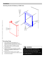
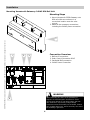
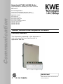
Versatronik® 535 & 535D Solar Communication Gateway for solar controls BACnet IP Communication Document Applicable to: Versatronik 535 Solar/BACIP Wall Mount 704065 Versatronik 535D Solar/BACIP DIN Rail Mount 704066 Applicable Controls Resol Deltasol M Resol Deltasol BS Plus Resol Deltasol BS1/2/3/4 Resol Deltasol BX/BXL Resol Deltasol E/ES/BX/MX/SKSC3 Viessmann Vitosolic 200 Viessmann SCU 124 Viessmann SCU 224 Viessmann SCU 345 Technical, Installation and Configuration Information Cautionary Statement The information presented in this document is only to be used by those familiar with its application and use. IMPORTANT Read and save these instructions for future reference About these instructions ! Take note of all symbols and notations intended to draw attention to potential hazards or important product information. These include “WARNING”, “CAUTION” and “IMPORTANT”. See below. ! WARNING Indicates an imminently hazardous situation which, if not avoided, could result in death, serious injury or substantial product/property damage. KWE P/N 394043 Versatronik 535 Solar Gateway V1.0 09/2013 Technical information subject to change without notice ! CAUTION Indicates an imminently hazardous situation which, if not avoided, may result in minor injury or product/property damage. Warnings draw your attention to the presence of potential hazards or important product information. Cautions draw your attention to the presence of potential hazards or important product information CAUTION Static sensitive components may be damaged by improper handling or work within the control. Ensure all possible measures are taken to eliminate build-up of static electricity. IMPORTANT Helpful hints for installation, operation or maintenance which pertains to the product. Trademark Information RESOL® and DeltaSol® M are trademarks of RESOL. For more information please visit www.resol-gmbh.de BACnet® is a registered trademark of the American Society of Heating, Refrigerating and AirConditioning Engineers, Inc., 1791 Tullie Circle NE, Atlanta, GA 30329. Viessmann® and Vitotronic® are trademarks of Viessmann Werke GmbH & Co KG registered in the United States and other countries. For more information please visit: www.bacnet.org www.ashrea.org Please visit: www.viessmann.ca www.viessmann.us 2 Important Regulatory and Installation Requirements Codes The installation of this unit must be in accordance with local codes. KWE P/N 394043 Versatronik 535 Solar Gateway V1.0 09/2013 Technical information subject to change without notice All electrical wiring is to be done in accordance with the latest edition of CSA C22,1 Part 1 and/ or local codes. In the U.S. use the National Electrical Code ANSI/NFPA 70. The installing contractor must comply with the Standard of Controls and Safety Devices for Automatically fired Boilers, ANSI/ ASME CSD-1 where required by the authority having jurisdiction. Working on the equipment The installation, adjustment, service and maintenance of this unit must be done by a licensed professional heating contractor or persons who are qualified and experienced in the installation, service, and maintenance of similar products. There are no user serviceable parts on this control. Power supply Install power supply in accordance with the regulation of the authorities having jurisdiction or in absence of such requirements, in accordance with National Codes. Purpose of Device and Operation The Versatronik 535 Solar gateway provides a communication translation between applicable controls and DDC systems which are capable of BACnet IP communications. The Versatronik gateway may be either part of a control panel or stand-alone control device. 3 Please carefully read this manual prior to attempting installation. Any warranty is null and void if these instructions are not followed. The completeness and functionality of field supplied electrical controls and components must be verified by those installing the device ! WARNING More than one live circuit. See wiring diagram in this manual. Turn off power supply to control and damper/blower before servicing. Contact with live electrical components can result in serious injury or death Installation Mounting Versatronik Gateway—120VAC Unit KWE P/N 394043 Versatronik 535 Solar Gateway V1.0 09/2013 Technical information subject to change without notice 2 1 4 1 3 Mounting Steps 1. Mount Versatronik 535 Gateway in a convenient location near the solar control. Remove cover by loosening the two screws on either side of base to release the cover. 2. Fasten base to wall using field-supplied screws/fasteners. 3. Remove knockout and installed wire strain relief or box connector. Removal of remaining knockouts is required to make further connections. 4. Once all of the 120VAC and low voltage connections are complete and verified, reinstall the cover from Step 1. ! WARNING When extending wire there is the possibility of exposure to electromagnetic interference. Avoid running wires beside or near high voltage 120/240 VAC conductors. If proximity to high voltage conductors cannot be avoided, use stranded, twisted pair of shield design wire. Ensure that only one end of the shielding is grounded. Installation Mounting Versatronik Gateway—24VAC DIN Rail Unit Mounting Steps 1. Mount Versatronik 535D Gateway onto DIN rail within an enclosure in a convenient location near the solar control. 2. Make all the necessary connections including the 24VAC power connection. 2 1. 2. 3. 4. " ! ! " # BACnet IP connection. Solar Control Connection RJ45 Paralleled BUS connection 24VAC Power Connection Connection Overview 3 1 KWE P/N 394043 Versatronik 535 Solar Gateway V1.0 09/2013 Technical information subject to change without notice 1 ! ! 4 WARNING When extending wire there is the possibility of exposure to electromagnetic interference. Avoid running wires beside or near high voltage 120/240 VAC conductors. If proximity to high voltage conductors cannot be avoided, use stranded, twisted pair of shield design wire. Ensure that only one end of the shielding is grounded. 5 Connection Overview RJ45 Communication Cable Supplied Connection Overview KWE P/N 394043 Versatronik 535 Solar Gateway V1.0 09/2013 Technical information subject to change without notice 1. Cut UTP cable to 2m length. 2. Strip insulation and crimp plug on one end. 3. Strip other end, cut all wires but wire 1 and 2. 4. Strip wire 1 and 2. 5. Wires 1 and 2 used to make connections to the solar control. 6 Versatronik 535 Dial Setting Overview Rotary Dial Setting Setting Overview 1. The rotary dial setting on the Versatronik Gateways provides addressing information for systems that may utilize a number of Versatronik Gateways. Applications with the Versatronik 535 Solar with RESOL controls, it is not required to make adjustments to the rotary dial setting. It should be left in the factory default position setting of 0. 1 + #$ % % ( ( ( ) * ( + & & & ' KWE P/N 394043 Versatronik 535 Solar Gateway V1.0 09/2013 Technical information subject to change without notice !" 7 Connection Overview—120VAC Unit BACnet IP Communication connections to BMS: Example: Resol Deltasol BS Plus Connection Overview 1 Control sensor portion of control. 1 2 A CAT-5 cable is supplied with the Versatronik Solar Gateway. The RJ45 is plugged into the gateway and terminates into the control. 3 BMS connection. 2 BMS Connection 3 + #$ % % ) ( ( ( * ( + & & !" & ' KWE P/N 394043 Versatronik 535 Solar Gateway V1.0 09/2013 Technical information subject to change without notice 4 Standard plug-in power connection supply for the gateway. It requires 120VAC for its operation. 4 120VAC 8 Connection Overview—120VAC Unit BACnet IP Communication Connections to BMS: Example: Resol Deltasol M Connection Overview 1 Control sensor portion of control. V Bus 1 2 A CAT-5 cable is supplied with the Versatronik Solar Gateway. The RJ45 is plugged into the gateway and terminates into the control. 3 BMS connection. 2 BMS Connection 3 + #$ % % ) ( ( ( * ( + & & !" & ' KWE P/N 394043 Versatronik 535 Solar Gateway V1.0 09/2013 Technical information subject to change without notice 4 Standard plug-in power connection supply for the gateway. It requires 120VAC for its operation. 4 120VAC 9 Connection Overview—24VAC DIN Rail Unit BACnet IP Communication Connections to BMS: Example: Resol Deltasol BS Plus Connection Overview 1 Control sensor portion of control. 2 A CAT-5 cable is supplied with the Versatronik Solar Gateway. The RJ45 is plugged into the gateway and terminates into the control. 1 3 BMS connection. 2 BMS Connection 3 " ! " # ! KWE P/N 394043 Versatronik 535 Solar Gateway V1.0 09/2013 Technical information subject to change without notice 4 Standard plug-in power connection supply for the gateway. It requires 24VAC for its operation. 4 24VAC 10 ! Connection Overview—24VAC DIN Rail Unit BACnet IP Communication Connections to BMS: Example: Resol Deltasol M Connection Overview 1 Control sensor portion of control. 2 A CAT-5 cable is supplied with the Versatronik Solar Gateway. The RJ45 is plugged into the gateway and terminates into the control. V Bus 1 3 BMS connection. 2 BMS Connection 3 " ! # ! " KWE P/N 394043 Versatronik 535 Solar Gateway V1.0 09/2013 Technical information subject to change without notice 4 Standard plug-in power connection supply for the gateway. It requires 24VAC for its operation. 4 24VAC 11 ! Configuration of Gateway Configuring BACnet/IP Settings Connect your computer DIRECTLY to the BACnet interface of the gateway device, with no other devices attached (an isolated network). Either set your computer’s network connection to automatic IP Address (DHCP), or set your computer’s IP address to 192.168.88.90 (subnet mask 255.255.255.0) KWE P/N 394043 Versatronik 535 Solar Gateway V1.0 09/2013 Technical information subject to change without notice Restart the Gateway by cycling the power off and then on again. Open a browser window and insert the following URL: http://192.168.88.89/admin The default user name / password is "admin" and "admin" (without the quotes). This can be renamed in the Change Password screen. At this point you will see the Configuration pages. IMPORTANT: Make sure that you remember any changes made here. Configuration of Gateway Continued BACnet Device Settings You can now reconfigure these settings according to your network requirements. Make sure that you press SAVE on every screen where you make changes. The new setting will not take effect until the Activate Configuration screen has been confirmed. These configuration pages can now be accessed through both the 192.168.88.89 Address, as well as the one you have selected. KWE P/N 394043 Versatronik 535 Solar Gateway V1.0 09/2013 Technical information subject to change without notice The BACnet Device Settings screen looks like this: NOTE: The Device ID must be unique on the entire BACnet internetwork. The Restore Defaults and Change Password screens are very simplistic. When you select Activate Configuration, it will ask you if you want to SAVE your settings. This will then store your new settings and reboot automatically. You can now join the Gateway to the rest of your network, provided you have not specified a duplicate IP Address. Any Computer on the network should now be able to access these configuration screens. 13 BACnet Objects SCU224, SCU124, Deltasol BS Plus Deltasol 1/2/3/4 Deltasol-E Deltasol-ES Deltasol-BX Plus Deltasol-MX Deltasol-SKSC3 Analog Output 1 Controls temperature units - X X X X X X X X X Analog Input 1 Temperature Sensor 1 C or F X X X X X X X X X Analog Input 2 Temperature Sensor 2 C or F X X X X X X X X X Analog Input 3 Temperature Sensor 3 C or F X X X X X X X X X Analog Input 4 Temperature Sensor 4 C or F X X X X X X X X X Analog Input 5 Temperature Sensor 5 C or F X - X X X X X X Analog Input 6 Temperature Sensor 6 C or F X - X X X X X Analog Input 7 Temperature Sensor 7 C or F X - X X X X X Analog Input 8 Temperature Sensor 8 C or F X - X X X X X Analog Input 9 Temperature Sensor 9 C or F X - X X X Analog Input 10 Temperature Sensor 10 C or F X - X X X Analog Input 11 Temperature Sensor 11 C or F X - X X Analog Input 12 Temperature Sensor 12 C or F X - X X X - X X - X See following page for configuration notes KWE P/N 394043 Versatronik 535 Solar Gateway V1.0 09/2013 Technical information subject to change without notice Object Description Units 1 2 2 Deltasol-BX Deltasol-BXL/SCU345 Deltasol-M, Vitosolic 200 BACnet Objects Analog Input 13 Irradiation W/m , W/ft Analog Input 14 Pulse Counter 1 - Analog Input 15 Pulse Counter 2 - X - Analog Input 16 Error mask sensor open2 Binary X - X Analog Input 17 Error mask sensor short2 Binary X - X 2 X X X Analog Input 18 Sensor mask Binary X - Analog Input 19 Speed Relay 1 % X X X X X X X Analog Input 20 Speed Relay 2 % X X X X X X X X X Analog Input 21 Speed Relay 3 % X - X X X X X X Analog Input 22 Speed Relay 4 % X - X X X X X Analog Input 23 Speed Relay 5 % X - X X X Analog Input 24 Speed Relay 6 % X - X X Analog Input 25 Speed Relay 7 % X - X X Analog Input 26 Speed Relay 8 % X - X Analog Input 27 Speed Relay 9 % X - X Analog Input 28 Speed Relay 10 % X - Analog Input 29 Speed Relay 11 % - - X7 X Analog Input 30 Speed Relay 12 % - - X7 X 2 Analog Input 31 Relay mask Binary X X Analog Input 32 Error mask2 Binary X X 2 Analog Input 33 Warning mask Binary X - Analog Input 34 Option Mask / Schema Binary or Dec. - X3 Analog Input 35 Heat Quantity in Wh4 X X X X X X X X X5 X X6 X3 Wh - X X X X X Analog Input 36 4 Heat Quantity in KWh Wh - X X X X X Analog Input 37 Heat Quantity in MWh4 Wh - X X X X X Analog Input 38 Operating Hours 1 Hours - X X X X Analog Input 39 Operating Hours 2 Hours - X X X X 14 KWE P/N 394043 Versatronik 535 Solar Gateway V1.0 09/2013 Technical information subject to change without notice Units Analog Input 40 Operating Hours 3 Hours X X Analog Input 41 Operating Hours 4 Hours X X Analog Input 42 Operating Hours 5 Hours X X Analog Input 43 Operating Hours 6 Hours X Analog Input 44 Zone Supply 1 C or F X Analog Input 45 Zone Supply 2 C or F X Analog Input 46 Zone Supply 3 C or F X Analog Input 47 Zone Supply 4 C or F Analog Input 48 Zone Status 1 X Analog Input 49 Zone Status 2 X Analog Input 50 Zone Status 3 X Analog Input 51 Zone Status 4 Analog Input 52 Flow Volume (VFS Sensor) X X l/h or gpm X BACnet Objects Configuration Notes 1 0 for Celsius, 1 for Fahrenheit 2 Convert to binary Bit 0: Sensor/Relay 1 (least significant bit, furthest to the right) Bit 1: Sensor/Relay 2 Etc. 3 Convert to binary: Bit 0: Collector cooling, collector 1 (OCX) Bit 1: Minimum limitation, collector 1 (OCN) Bit 2: Antifreeze, collector 1 (OCF) Bit 3: Tube collector special function (OTC) Bit 4: Re-cooling function (OREC) Bit 5: Heat quantity measurement (OHQM) 4 Values roll over when reaching the next base-1000 magnitude (i.e. 999 Wh becomes 0 Wh + 1 KWh.) 5 System Arrangement 6 Convert to binary: 7 Deltasol-SKSC3 Description Deltasol-MX Object Deltasol-BX Plus Deltasol-BX Deltasol-BXL/SCU345 Deltasol-ES Deltasol-E Deltasol 1/2/3/4 See configuration notes below SCU224, SCU124, Deltasol BS Plus BACnet Objects Continued Deltasol-M, Vitosolic 200 BACnet Objects Bit 0: Broken sensor Bit 1: Short circuit sensor Bit 2: DT high Bit 3: Warning circulation at night Speed Pulse Width Modulation (PWM) 1,2 15 X X X Technical Information 3 7 8 + #$ 9 % % ) ( ( ( ( * & ' KWE P/N 394043 Versatronik 535 Solar Gateway V1.0 09/2013 Technical information subject to change without notice + 6 & & 5 !" 10 4 2 1 PCB Identifiers Specifications 1 120VAC Power Supply Connections Voltage Requirements 120VAC 2 Fuse Fuse Rating 160mA Time Delay 3 Service Button Power 4VA 4 LON Connections to BMS 5 RJ45 Connection to BMS BACnet Communication Connections Supplied cable between devices 6 Addressing selector for multiple modules 7 COM3 for multiple BUS connections 8 COM4 RJ45 Connection to control 9 Power LED indicator CAUTION Static sensitive components may be damaged by improper handling or work within the control. Ensure all possible measures are taken to eliminate build-up of static electricity. 10 Service LED 16 Technical Information 4 6 7 ! " # ! KWE P/N 394043 Versatronik 535 Solar Gateway V1.0 09/2013 Technical information subject to change without notice " 9 8 2 5 3 ! 1 PCB Identifiers Specifications 1 24VAC Power Supply Connections Voltage Requirements 24VAC 2 Power LED indicator Fuse Rating N/A 3 BACnet RJ45 BMS Connection Power 4VA 4 Addressing dial for multiple units 5 COM4 RJ45 Connection to control Communication Connections Supplied cable between devices 6 COM3 for multiple BUS connections 7 Service button 8 Service LED 9 LON Connections to BMS CAUTION Static sensitive components may be damaged by improper handling or work within the control. Ensure all possible measures are taken to eliminate build-up of static electricity. 17 KWE P/N 394043 Versatronik 535 Solar Gateway V1.0 09/2013 Technical information subject to change without notice KWE Technologies Group 750 McMurray Road Waterloo, Ontario, Canada N2V 2G5 Tel: (519) 747-5042 Fax: (519) 747-4448 www.kwe-tech.com [email protected] 18