1
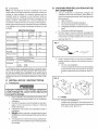
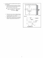
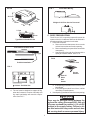
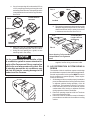
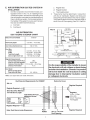
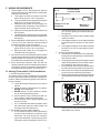
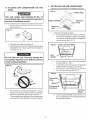
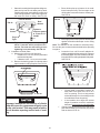
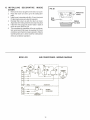
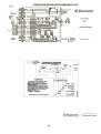
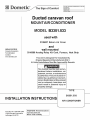
SAFETY INSTRUCTIONS
1. GENERAL INFORMATION
A. Product features or specifications as described or illustrated are subject to change without notice.
The following are the basic requirements:
1. Installation opening. Cut through the roof and ceiling.
2. Additional Wiring.
220-240 VAC, 50 Hz. 10 Amp.
3. Power with the air conditioner on must be above 209
VAC and the frequency must be at 50 HZ. at all
times.
B. This Air Conditioner Is Designed For:
This manual has safety information and instructions to help users eliminate or reduce the risk of
accidents and injuries.
RECOGNIZE SAFETY INFORMATION
!
This is the safety-alert symbol. When you see this
symbol in this manual, be alert to the potential for
personal injury.
C.
Follow recommended precautions and safe operating instructions.
UNDERSTAND SIGNAL WORDS
A signal word , WARNING OR CAUTION is used
with the safety-alert symbol. They give the level of
risk for potential injury.
! WARNING indicates a potentially hazard-
1. Installation on a Caravan during the time the vehicle is manufactured.
2. Mounting on the roof of a Caravan.
3. Roof construction with rafters/joists on minimum of
40.6 cm centers.
4. Minimum of 5 cm and maximum of 10 cm distance
between roof to ceiling of Caravan.
The ability of the air conditioner to maintain the desired
inside temperature depends on the heat gain of the
Caravan.
Some preventative measures taken by the occupants of
the Caravan can reduce the heat gain and improve the
performance of the air conditioner. During extremely
high outdoor temperatures, the heat gain of the vehicle
may be reduced by:
1. Parking the Caravan in a shaded area
2. Using window shades (blinds and/or curtains)
3. Keeping windows and doors shut or minimizing
usage
4. Avoiding the use of heat producing appliances
Operation on High Fan/Cooling mode will give optimum or
maximum efficiency in high humidity or high outside temperatures.
ous situation which, if not avoided, could result in
death or serious injury.
Starting the air conditioner early in the morning and giving it
a "head start" on the expected high outdoor ambient will
greatly improve its ability to maintain the desired indoor
temperature.
! CAUTION indicates a potentially hazardous situation which, if not avoided, may result in
minor or moderate injury.
For a more permanent solution to high heat gain, accessories like Dometic A&E outdoor patio and window awnings will
reduce heat gain by removing the direct sun. They also add
a nice area to enjoy company during the cool of the evening.
CAUTION
used without the safety alert
symbol indicates, a potentially hazardous situation which, if not avoided, may result in property
damage.
Read and follow all safety information and instructions.
2
FIG. 5A
FIG. 7
Force While Moving
32.5 cm
75 cm
87 cm
1.5 cm
Weight of A/C Plus Service Personnel
43
cm
C. ROOF PREPARATIONS
43 cm
The 35.5 cm x 35.5 cm opening is part of the return air
system of the Air Conditioner and must be finished in
accordance with any national or local codes.
1. Roof Vent Locations:
a. Remove all screws that secure the vent to the
roof and remove the vent from the opening.
b. Remove all sealing compound from around the
vent opening.
c. Seal all screw holes and all roof seams with a
quality all weather sealant. See FIG. 8.
Type B3351.533 & B3351.534
Roof /Return Air Grill - Cross
Section
35.5 cm
Light
FIG. 8
Remove Screws
Prohibits Installation
Remove Vent
FIG. 6
Scrape
Sealant
Seal All
Holes
And
Seams
Cabinet - Prohibits Use
d. The roof must be designed to support 60 Kg.
when the Caravan is in motion. Normally a 90
Kg. static load design will meet this requirement. See FIG. 7.
2.
d. If the opening is less than 35 cm x 35 cm, it must
be enlarged.
e. If the opening exceeds 36 cm x 36 cm, it will be
necessary to install spacers.
New Opening (installation other than vent opening)
! WARNING
There may be electrical wiring between the
roof and the ceiling. Disconnect 220 - 240 volt
AC power cord and the positive (+) 12 volt DC
terminal at the supply battery. Failure to follow this instruction may create a shock hazard causing death or severe personal injury.
5
a. If a roof vent opening will not be used a 35.5 cm
x 35.5 cm opening must be cut through the roof
and ceiling of the Caravan. This opening must be
located between the roof reinforcing members.
See FIG. 9.
Do Not Remove
Structure
FIG. 9
Do Not Cut Electrical
Wires
FIG. 11
Cut Hole
d. The opening created must be framed to provide
adequate support and prevent air from being
drawn from the roof cavity. Lumber 2 cm or more
in thickness must be used. See FIG. 12.
No Blockages
2 cm
Depends On
Structure
38 cm Min Wire
Length At Front
Of Opening
Good
FIG. 12
b. Mark a 35.5 cm x 35.5 cm square on the roof and
carefully cut the opening. See. FIG. 10, 11 & 12.
c. Using the roof opening as a guide, cut the
matching hole in the ceiling.
Frame Opening To Prevent Roof
collapse When Unit Tightened
Down
CAUTION
It is the responsibility of the installer of this
air conditioner system to ensure structural integrity of the Caravan roof. Never create a low
spot on the roof where water will collect. Water standing around the air conditioner may
leak into the interior causing damage to the
product and the Caravan.
Remember to provide an entrance hole for power
supplies, furnace wiring, and control cable.
D. AIR DISTRIBUTION SYSTEM SIZING &
DESIGN
The Installer of this air conditioner system must design
the air distribution system for their particular application.
Several requirements for this system MUST be met for
the air conditioner to operate properly. These requirements are as follows:
1. All discharge air ducts must be properly insulated to
prevent condensation from forming on their surfaces
or adjacent surfaces during operation of the air
conditioner. This insulation must be R-7 minimum.
2. Ducts and their joints must be sealed to prevent
condensation from forming on adjacent surfaces
during operation of the air conditioner.
3. Return air openings must have 260 cm2 minimum
free area including the filter.
4. Return air to the air conditioner must be filtered to
prevent dirt accumulation on air conditioner cooling
surface.
FIG. 10
6
F. WIRING REQUIREMENTS
5 m Thermostat
Connector Cable
FIG. 15
Route a copper 1.5 mm2, with ground, 220 - 240 VAC
supply line from the time delay fuse or circuit breaker
box to the roof opening.
a. This supply line must be located in the front
portion of the 35.5 cm x 35.5 cm opening.
b. The power MUST be on a separate 10 Amp time
delay fuse or 10 Amp circuit breaker.
c. Make sure that at least 38 cm of supply wire
extends into the roof opening. This ensures an
easy connection at the junction box.
d. Wiring must comply with all National and Local
Wiring Codes.
e. Use a steel sleeve and a grommet or equivalent
methods to protect the wire where it passes into
the opening.
2. Route a dedicated 12 VDC supply line (0.50 mm2 to
0.75 mm2) from the Caravan's converter (filtered
terminals) or battery to the roof opening.
a. This supply line must be located in the front
portion of the 35.5 cm x 35.5 cm opening.
b. Make sure that at least 38 cm of supply wire
extends into the roof opening.
3. If a furnace is to be controlled by the system, the two
furnace thermostat leads must be routed to the roof
opening. Make sure at least 38 cm of the furnace
thermostat wires extend into the roof opening.
4. Route thermostat connector cable into the roof
opening. Make sure 38 cm of cable extends into the
roof opening, and 10 cm extends from the wall at the
thermostat mounting location. See Section G-2.
1.
Female End To Air
Conditioner
Male End To
Thermostat
b. Choose the shortest, direct route from the 35.5
cm x 35.5 cm opening to the thermostat location selected.
c. Consider where screws, nails or staples might
contact the cable.
d. Leave approximately 10 cm of cable extending
through the wall for connection to the thermostat.
e. Leave approximately 35 cm of cable extending
into the 35.5 cm x 35.5 cm opening for connection at unit.
3. Analog Thermostat Installation.
a. Connect the Thermostat Connector Cable protruding from the wall onto the pre-wired thermostat connector cable.
b. Gently push the two connectors together until a
snap is heard and the lock on the male connector is latched on the female connector.
c. Gently feed the connectors through the hole in
the wall until the thermostat can mount flush.
d. Remove the cover from the thermostat by starting at one corner and lifting it off the base.
e. Mount the thermostat level on the wall using the
screws provided in the locations shown in figure.
16.
G. Analog Thermostat & Cable Installation
1. Analog Thermostat Location
The proper location of the thermostat is very important
to ensure that it will provide a comfortable Caravan temperature. Observe the following general rules when selecting a location:
a. Locate the Analog Thermostat 140 cm above
the floor.
b. Install the Analog Thermostat on a partition,
NEVER on an outside wall.
c. NEVER expose it to direct heat from lamps,
sun or other heat producing items.
d. Avoid locations close to doors that lead outside, windows or adjoining outside walls.
e. Avoid locations close to supply registers and
the air from them.
f. A 2.5 cm diameter hole will be needed to route
the thermostat connector cable female end
through the wall. See Section F-4.
2. Thermostat Connector Cable Installation.
a. A Thermostat Connector Cable is provided to
connect the air conditioner control box to the
thermostat. The male end of this connector
goes to the thermostat. The female end of the
cable goes to the air conditioner. See FIG. 15.
FIG. 16
HS +7.5 COOL FUR HI FAN GND
HP
FAN
Screw Locations
f.
8
Place the cover on the thermostat and push until
and audible click is heard.
f.
Start each mounting bolt through the ceiling template and up into the unit base pan by hand.
Install wood screw (not supplied) in each end
of the ceiling template. This insures a tight fit of
the return air cover to ceiling. See FIG. 22.
c. Place divider plate up to bottom of air conditioner base pan firmly. The foam tape on the
divider plate must seal to bottom of base pan.
See FIG. 24.
FIG. 24
Front of Vehicle
Roof
Gasket
FIG. 22
Tighten to
compress gasket
to 13 mm or 4.5 5.0 NM
Wood
Screws
Finger
Tight
d. With slight pressure then push the divider plate
against the double sided tape on the ceiling
template.
Note: The adhesive on the insulation is extremely sticky.
Be sure the part is located where desired before pressing
into place.
e. Locate the 18 cm x 45.5 cm self -adhesive insulation supplied with the return air kit. Remove
the backing paper from the insulation and carefully stick onto the ceiling template divider panel.
See FIG. 25.
Tighten mounting bolts to compress gasket to 13 mm this will be a torque of 4.5 5.0 Nm. The bolts are self locking so over
tightening is not necessary. See FIG. 22.
2. Installation of Divider Plate
a. Measure the ceiling to roof thickness:
• If distance is 5 - 9.5 cm, remove perforated
tab from divider plate.
• If distance is 9.6 - 14 cm, remove no tabs.
b. Remove the backing paper from double sided
tape located on ceiling template. See FIG. 23.
FIG. 25
FIG. 23
•
5 - 9.5 cm
CAUTION
Improper installation and sealing of divider
plate will cause the compressor to quick cycle
on the cold control. This may result in fuse or
circuit breaker opening and/or lack of cooling.
f.
10
Excess width is intended to seal the divider plate to the sides of the 35.5 cm x
35.5 cm opening. This is to help prevent
cold air discharge from circulating into the
air conditioner return air opening.
• If the insulation is too high, stick excess
height of insulation to the air conditioner
base pan. Do not cover up unit rating plate.
Place the analog control box on the ceiling template with the white 6 pin connector plug on the
side as shown in FIG. 26.