1
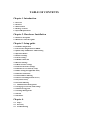
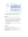
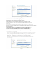
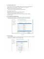
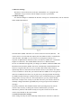
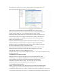
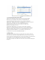
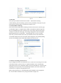
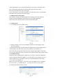
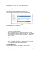
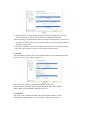
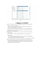
DT-05PTWR300MB
IEEE802.11 b/g/n 300Mbps Wireless Router
USER'S GUIDE
Version l.0
TABLE OF CONTENTS
Chapter l. Introduction
1.1 0verview
1.2 Features
1.3 Environment
1.4 Package contents
1.5 System Requirements
Chapter 2. Hardware Installation
2.1 Interface description
2.2 Hardware connection guide
Chapter3. Setup guide
3.1 TCP/IP Configuration
3.1.1 Network Configuration for DHCP
3.2 Quick setup of PPPoE for ADSL sharing
3.3 0peration Modes
3.4 Internet Settings
3.4.1 WAN settings
3.4.3 DHCP Clients list
3.5 Wireless Settings
3.5.1 Basic wireless settings
3.5.2 Advanced wireless settings
3.5.3 Wireless Access Security setup
3.5.4 WPS setting(for applicable units)
3.5.5 Wireless Station list
3.6.1 MAC/IP/Port Filtering
3.6.2 Port Forwarding(Virtual Server)
3.6.4 System Security
3.6.5 Content Filtering
3.7 Administration management
3.7.1 Language, Password, NTP settings
3.7.2 Firmware Upgrade
3.7.3 Settings Management
3.7.4 Status
3.7.5 Statistics
Chapter 4.
4.1 FAQ’s
4.2 Warranty
4.3 Troubleshooting
4.4 Legal Notice
Chapter l Introduction
1.1 0verview
The DT-05PTWR300MB is a high performance wireless broadband router that integrates Wireless
AP, NAT-Router, 4 port Ethernet switch and a Firewall. It supports 802.11 b/g/n to supply
300Mbps of wireless bandwidth. The unit can be set to bridge or gateway mode and provide one
10/100Mbps WAN port to connect to the internet and four 10/100Mbps switch LAN ports to
expend your LAN. The DT-05PTWR300MB supports STATIC IP/DHCP
Client/PPPoE(ADSLyL2TP/PPTP) WAN connection types. It has a built in high performance
DHCP server and supports VPN Pass through. Firewall functions include MAC/IP/Port filter
and Content filter. Port forwarding ,DMZ, NTP and DDNS are supported. Wireless access
security modes are: WEP/WPA/WPA-PSK/WPA2/WPA2-PSK. Wi-Fi Protected Setup (WPS)
function. Language Supported is English for the WEB setup interface. Firmware is upgradeable
as needed.
1.2 Features:
Complies with IEEE802.11 b/g/n for wireless access
Supports a variety of wireless access security modes
Supports 64/128-bit WEP encryption security
Support WPA/WPA-PSK/WPA2/WPA2-PSK authentication and TKIP/AES
encryption security
Supports WPS easy wireless connect function
Complies with IEEE802.3 10Base-T and IEEE802.3u 100Base-TX Fast Ethernet
standards for wired LAN
One 10/100Mbps RJ45 WAN port for Internet connection
Built in four port l0/100Mbps Ethernet switch for wired LAN, Supports Auto
MDI/MDIX
Can be set to Bridge mode and Gateway mode
WEB based setup and management interface in English
Built in high performance DHCP server with monitoring of the DHCP clients
through web setup interface
Supports MAC address and IP address binding
Supports MAC address CLONE
Supports WDS
VPN Pass through support of L2TP, IPSec, and PPTP protocols
Monitoring of wireless stations connected to this device through the web interface
High performance firewall functions include: MAC address filter, IP address filter,
Port filter, Content filter(URL and host name filter)
Supports Port forwarding and DMZ host
Changeable password by the administrator through the web setup software
System sync time with NTP server by NTP setting
Supports DDNS(Dynamic DNS) setting
Can backup and re-load current settings of the device.
Can monitor the status of the device and the statistics of the communications through web setup
software
Firmware upgrade support of root files upgrade, Uboot upgrade, and Factory Settings upgrade
1.3 Parameters and Environments
. Size: 5 7/8”(L)X4 ½”(W)X1 ¼” (H) 147(L)x113(W)x32(H)mm
. NW: 7.5 oz 206g
. Power Supply: Input AC110, Output DC9V/1A
. Consumption: 7.5W(MAX)
. Storage Temperature: -40°F to 178°F -40°C to 70 °C
. Operating Temperature: 14°F to 122°F -10°C to 50°C
. Storage Humidity: 5%-95% RH Non-condensing
. Operating Humidity: 10%-90% RH Non-condensing
1.4 Package contents
. One Wireless Broadband Router
. One Power Adapter
. User's manual
1.5 System Requirement
. One DSL/Cable Modem
. One l0M or l0/100M ethernet card installed on your PC
. TCP/IP protocol installed on each PC
. RJ45 Twisted-pair
. Microsoft IE8.0 or later or other Internet Explorer software
Chapter 2. Hardware Installation
2.1 Interface description
2.2 Hardware connection guide
The chart is for reference only.
Chapter 3. Setup guide
3.1 TCP/IP Configuration
1 . Click the Start button, then click Control Panel.
2. Double click the Network icon and select the Create a new connection in the Network window.
Follow the network wizard instructions until conclusion, then skip to step 6.
If you have installed TCP/IP protocol before, please skip to step 6.
3. Click the Add button to add network adapter into your computer.
4. Double click Protocol to add TCP/IP protocol.
5. Select Microsoft item in the manufactures list, Choice TCP/IP in the Network
protocols, Click OK button to return to Network window.
6. The TCP/IP protocol should be listed in the Network window. Double click
TCP/IP to set the TCP/IP protocol.
7. Select Obtain an IP address automatically in the, IP Address table .
8. Click OK to complete the install procedure and restart your computer to enable
the TCP/IP protocol.
3.1.1 Network Configuration for DHCP
Windows Vista
1. Select Network and Sharing in the Control Panel.
2. Click View Status click Properties.
3. Click Continue in the User Account Control window.
4. In the General tab of the Local Area Connection Properties window select Internet
Protocol Version 4 (TCP/IPv4), click Properties.
5. Click the Obtain an IP address automatically button.
6. Click the Obtain DNS server address automatically button.
7. Click OK in the Internet Protocol Version 4(TCP/IPv4) Properties window,
8. Click OK in the Local Area Connection Properties screen to save the settings.
Windows 7
1. Click View Network Status and Tasks in the Control Panel.
2. Click Local Area Connection, click Properties.
3. Click Internet Protocol Version 4 (TCP/IPv4), click Properties.
4. Click the Obtain an IP address automatically button.
5. Click the Obtain DNS server address automatically button.
6. Click OK in the Internet Protocol Version 4(TCP/IPv4) Properties window,
7. Click OK in the Local Area Connection Properties screen to save the settings.
Windows XP
1. Select Network Connections in the Control Panel.
2. Right-click Ethernet Local Area Connection, then click Properties.
3. In the “General” tab, select Internet Protocol (TCP/IP), click Properties.
4. The Internet Protocol (TCP/IP) Properties window appears.
5. Click the Obtain an IP address automatically button.
6. Click the Obtain DNS server address automatically radio button.
7. Click OK in the Internet Protocol (TCP/IP) Properties screen, click OK in the Local Area
Connection Properties screen to save the settings.
Windows 2000
1. Select Network Connections in the Control Panel.
2. Right-click Ethernet Local Area Connection, then click Properties.
3. In the “General” tab, select Internet Protocol (TCP/IP), click Properties.
4. Click the Obtain an IP address automatically button.
5. Click the Obtain DNS server address automatically radio button.
6. Click OK in the Internet Protocol (TCP/IP) Properties screen, click OK in the Local Area
Connection Properties screen to save the settings.
Macintosh OS X
1. Click on the Apple icon in the top left corner of the desktop.
2. From the menu that appears select System Preferences.
3. The “System Preferences” window appears. Network.
4. From the Network window, make sure Ethernet (Built in Ethernet) in the list on the left is
highlighted and displays Connected.
5. From the Configure drop down menu, choose DHCP.
6. Click the Apple icon to save.
3.2 Quick setup of PPPoE forADSL sharing
This will guide you to quick setup PPPoE connect with an ADSL modem to share the
Internet.
1 . Connect the LAN adapter on your PC with one of LAN ports of the wireless router,
then power it on. The PC will get an IP address.
2. Open the web browser on your PC(e.g. IE), type http://192.168.8.1 in the address
field , then press Enter. Input the default User name admin and the default password admin,
then click OK button.
3. Select Gateway operation mode as in figure4
4. Click the Configuration Menu - Internet Settings - WAN, Select PPPoE (ADSU for
WAN connection type, then input your ADSL User Name and Password you received
From your ISP into the corresponding fields, as follows, then click the Apply button.
5. Click Wireless Settings – Basic and Input your Network Name (SSID). Keep other
default parameters indicated in figure 6, then click Apply.
6. Setup wireless access security to prevent unauthorized access:
Options are: WPA/WPA 2/WPA-PSKIWPA2-PSK Security
Note for WPA Algorithms: TKIP is only for 54Mbps,
Input a Password in the Pass Phrase table, then click Apply.
7. Connect the WAN port of this Router with the LAN port of the ADSL modem, then
reboot the Router and ADSL modem. You can share the internet connection.
For the settings of the ADSL modem please refer to its user's guide.
3.3 0peration Mode
Please refer to fig 4 in 3.2.3, you can set this device to Bridge or Gateway
mode.
1 . Bridge mode: All ethernet and wireless interfaces are bridged into a single
bridge Interface. WAN settings do not need to be set in the Internet Settings menu.
2. Gateway mode: The first ethernet port is treated as the WAN port. The other
ethernet ports and the wireless interface are bridged together and are treated
as LAN ports. WAN settings must be set in the Internet Settings menu.
3. After you have selected a mode, wait for the device to reboot, then refresh
the setup WEB page.
Note: In Gateway mode, If you want to let PCS aquire lP addresses automatically,
you must Enable the NAT.
3.4 Internet Settings
3.4.1 WAN settings
This device provides 5 WAN connection types:
STATIC (fixed IP) DHCP (Auto config) PPPoE(ADSL) L2TP PPTP.
Select the WAN connection type required by your ISP(lnternet Service Provider),
then input the parameters into corresponding fields, click Apply.
3.4.1.1 STATIC (fixed lP)
If your ISP assigns you a fixed IP address, Select STATIC(fixed lP) as figure. 8:
IP Address: Enter the IP address assigned by your ISP.
Subnet Mask: Enter the Subnet Mask assigned by your ISP.
Default Gateway: Enter the Gateway assigned by your ISP.
Primary DNS Server: Enter the Primary DNS IP address assigned by your ISP.
Secondary DNS Server: Enter the Secondary DNS IP address assigned by your ISP.
MAC Clone:
In some instances the ISP provides a fixed MAC address for your PC to connect to the
Internet, you can input the MAC address into the MAC Clone field to let your LAN share the
Internet connection.
The default MAC address is set to the WAN's physical interface MAC address on
the Router, So it's not recommended that you change the default MAC address.
Note: You can use the MAC Clone function option for each WAN connection type.
3.4.1.2 DHCP(Auto config) mode
If you connect to the Internet through the LAN of your ISP and do not subscribe to a fixed IP
service, you will get a different IP address each time you log on, in this case, please select
DHCP mode. The Hostname is optional but may be required by some ISPs.
If needed, you can Enable the MAC Clone function and fill in the MAC address table,
then click Apply.
3.4.1.3 PPPoE(ADSL) mode
If you connect to the Internet through a DSL line, check with your ISP if they use
PPPoE, If they do, select PPPoE. Refer to figure 5 in 3.2.4 (page 7).
Enter User Name and Password from the ISP,
You can select one Operation mode from following three:
Keep Alive: Always online;
On Demand: Connect to Internet only when you need it;
Manual: Connect to Internet manually every time.
If required, enable the MAC Clone function and input the MAC address,
then click Apply.
3.4.1 .4 L2TP mode and PPTP mode
The setting of this two mode is similar to above. Make sure of the correct
connection mode and input the User Name and Password for your IS P.
3.4.2 LAN settings
As in the following figure 11, modify the IP address of this device; Enable or Disable
DHCP Server and define the DHCP address range.
Set the IP Address and Subnet Mask to your internal network settings.
Unless you have specific internal network needs, these should be no reason to change
the values.
DHCP Type: Can be set to Disable or Server mode. If the Server mode is
selected, configure your computers to automatic IP allocation mode. When
your computer is powered on, it will automatically load the proper TCP/IP
settings from this device.
Start IP Address: Define an IP address for the DHCP server to start with when
issuing IP address. This address cannot be the same as the IP Address of this device.
End IP Address: Define an End IP address for the DHCP server, it must be greater
than the Start IP Address,
Primary DNS Server: Enter the Primary DNS IP address assigned by your ISP. This
is optional.
Secondary DNS Server: Enter the Secondary DNS IP address assigned by your
ISP. This is optional.
Default Gateway: Normally it's same as the IP Address of this device.
3.4.3 DHCP Clients list
The table lists the information about the hosts which have obtain an lP address
from the DHCP server of this router. As following fig. 1 2.
3.4.4 VPN Pass through
VPN Pass through can help you to achieve remote access to your LAN through an outside
Internet connection.
This device can be set to pass through VPN data packats based on the following protocols:
PPTP, L2TP, IPSec. Enable the protocols you need on the setup page as per figure 13, then click
Apply.
3.5 Wireless Settings
This device can let all wireless nodes (PC, Smart Phone, etc.) equipped with
a IEEE802.11/b/g/n wireless network adapter connect to your Intranet.
3.5.1 Basic Settings
You should configure at minimum the Wireless settings for communication, such as Network
Name (SSID) and Channel.
Network Name (SSID): The name of a wireless local area network (WLAN). All
wireless devices on a WLAN must employ the same SSID in order to communicate
with each other. The SSID is a case sensitive text string and is made up of a
sequence of alphanumeric characters (letters or numbers). SSID’s have a maximum
length of 32 characters. The default SSID of this device is Wireless Router,
but it is recommended strongly that you change your SSID to a different SSID name.
Broadcast Network Name (SSID): The router automatically transmit SSID into the
airwaves at regular intervals (every few seconds). This feature allow clients to
dynamically discover and roam between WLANs. However, this feature also makes
it easier for hackers to break into your network. Because SSIDs are not encrypted or
otherwise scrambled, It becomes easy to grab one by snooping the WLAN looking
for SSID broadcast messages coming from the router or WAP. Knowing your SSID
brings hackers one step closer to a successful intrusion, you may want to disable
this feature to improve the security of your WLAN. Once your wireless clients are
manually configured with the right SSID, they no longer require these broadcast
messages.
Frequency (Channel): This field determines which operating frequency will be
used. It is not necessary to change the wireless channel unless you notice
interference problems with another nearby access point. All devices in the same
wireless LAN should use the same channel.
3.5.2 Advanced wireless settings
These settings are only for more technically advanced users who have a sufficient
knowledge about wireless LAN. These settings should not be changed unless you
know what effect the changes will have on your Access Point.
Beacon Interval: Beacon frames are transmitted by an access point at regular
intervals to announce the existence of the wireless network. The default behavior is
to send a beacon frame once every 100 milliseconds (or 10 per second).
Data Beacon Rate (DTIM): Indicates rate that the access point will advertise to the
network for the purposes of setting up communication with other APs and client
stations on the network. It is generally more efficient to have an AP broadcast a
subset of its supported rate sets.
Fragment Threshold: Setting the Fragment Threshold can limit the size of packets
(frames) transmitted over the network. If a packet exceeds the fragmentation
threshold set here, the fragmentation function will be activated and the packet will
be sent as multiple 802.11 frames. The default is 2346.
RTS Threshold: The RTS threshold specifies the packet size of a request to send
(RTS) transmission. This helps control traffic flow through the access point,
especially one with a lot of clients. The default is 2347
TX Power: Set from l - 100 to control the RF output power. This controls the distance of the
RF signal transmitted.
3.5.3 Wireless Access Security setup
Setup the wireless security and encryption to prevent unauthorized access and
monitoring. It is recommended strongly that you choose this option to encrypt your
wireless network. The Security mode supports WEP(Open/Shared/Auto),
WPA/WPA- PSK/WPA 2/WPA 2-PSK. You must setup the same security
parameters both on your router and the wireless client devices.
3.5.3.1 WEP(Open/Shared/Auto)
WEP is a protocol that adds security to WLAN based on the 802.11b standard . WEP
was designed to give wireless networks the equivalent level of privacy protection as
a comparable wired network. As per figure 16 below, You can pre-set 4 WEP keys. The format
can be ASCII or Hex string, Only the key you selected in the Default Key setting will be used.
3.5.3.2 WPA/WPA-PSK/WPA2/WPA2-PSK
WPA provides significantly stronger wireless data encryption than WEP.
Refer to fig. 7 in 3.2.6(page 8). You can choice a Security Mode from:
WPA/WPA-PSK/WPA 2/WPA 2-PSK then choice a WPA Algorithm from:
TKIP or AES. TKIP is only for 802.11 b/g (54Mbps max). For faster connection
speeds greater than 54Mbps, select AES or TKIP WPA algorithms.
If WPA or WPA2 is to be selected, you must Enter the settings of the
Radius Server (lP address, Port, etc.).
If WPA-PSK or WPA2-PSK is to be selected, you must input a Pass Phrase.
Radius Server: In WPA authentication mode, the keys can be managed using two
different mechanisms: WPA can either use an external authentication server (e.g.
RADIUS) and EAP like IEEE802.1x, or pre-shared keys without the need
for additional servers(as above WPA-PSK,WPA2-PSK.. .).
3.5.4 WPS setting
WPS (WiFi Protected Setup) can help you quickly and easily setup the connection
between the router and clients. Using the WPS function, you do not need to select the
Security mode and set the Encryption Key. You just need to input the correct PIN code or
select the PBC (or press the WPS button on the front panel) to setup WPS.
Select Wireless Settings: Select WPS in the main menu to enter the WPS setting page as
In figure 17:
WPS: Enable or Disable the WPS function. The default is Disable.
WPS mode: You can set the WPS mode in WPS Progress section, There are two modes
for your selection: PIN code or PBC (Push-Button Configuration).
PIN mode: If you select the PIN mode WPS, you must know the PIN code of the client
node and input the PIN into the PIN field. You also can press the Generate button in the WPS
Summary field to generate a PIN code as the common PIN code for the router and clients.
The router and clients must use the same PIN code.
PBC mode: Select PBC then press Apply, or push the WPS button on the front
panel for about l second. Use the WPS/PBC mode in client nodes to connect with the router.
WPS button operation: After you push the WPS button for 1 second, the WPS indicator will blink
for about 2 minutes. This means the WPS is sending out signals during this period of time.
The client device can authenticate by WPS/PBC function during this time.
After a successful connection, the WPS indicator will shut off. You can repeat this step
For up to 32 client connections.
WPS Status:
Idle - WPS service is in standby.
Start MAC process - WPS access has started and is waiting for clients connect.
Configured - Client has authenticated successfully and connected.
Reset OOB: After you press this button, the WPS server will go to the Idle status.
The WPS indicator will shut off. The AP will not respond to any WPS request from the clients
The system will set the Security mode into WPA.
3.5.5 Wireless Station list
Select Wireless Settings, then select Station List in the main menu, and view the Station list table
as indicated in figure 18. Here you can monitor the client stations which are associated with the
Router through this table.
3.6 Firewall
The system provided firewall functions include: MAC/IP/Port filtering,
Content Filtering, Port Forwarding, System Security and DMZ, to help prevent your
network from a hacker attack or to limit some clients' access.
3.6.1 MAC/IP/Port Filtering
Select Firewall, then MAC/IP/Port Filtering from the main menu to enter the page
as indicated in figure 19. Input the MAC address or IP address and Port range into
the corresponding fields. Select a Protocol you want to filter, and select the action
of Drop or Accept, then click Apply. The setting will append to the Current MAC
IP Port filtering rules in system table. Repeating this step, you can set all the
filter rules you want into this table. After your finished, access from the Internet
or LAN that matches the rules in the table will be Dropped or Accepted depending
on the corresponding Action setting thus limiting the clients' access.
3.6.2 Port Forwarding (Virtual Server)
If you configure the router for Virtual Server use, remote users accessing services such
as the Web or FTP at your local site via a public IP address can be automatically
redirected to local servers configured within your private IP addresses. In other words,
depending on the requested server (TCP/UDP port number), the router redirects the
external service request to the appropriate server.
Before using Virtual Server, You should add a static IP address to the designated
PC. You can add a Virtual Server by using the interface in figure 20:
1. Select Virtual Server Settings to Enable;
2. Enter the IP address of the Virtual Server into the IP Address field;
3. Enter the Port range you want to forward into the Port Range field;
4. Select a Protocol of TCP, UDP, or TCP&UDP;
5. Enter the Service name into the Comment field;
Once done, click Apply to add into the Current Virtual Servers in the system table.
Repeat the above steps to add up to 32 Virtual Server settings.
You can select any current entry under Current Virtual Servers in the system table,
then click the Delete Selected button to delete it.
3.6.3 DMZ
If you have a client PC that cannot run an Internet application properly from behind
the NAT firewall or after configuring the Virtual Server, then you can open the client up
to unrestricted two-way Internet access.
Set the DMZ Settings to Enable, Enter the IP address of a DMZ host in the DMZ IP
Address field, then click the Apply button.
Adding a client to the DMZ (Demilitarized Zone) may expose your local network to a
variety of security risks. Evaluate this option carefully prior to using.
3.6.4 System Security
You may configure the system firewall to help prevent the AP/Router from an attack.
Click Firewall, then System Security from main menu. Enter the page as per figure 22.
1. You can Deny or Allow Remote management from the WLAN.
2. You can Enable or Disable Ping form the WAN.
3. You can Enable or Disable Stateful Packet Inspection (SPI).
3.6.5 Content Filtering
You can set the Web content filter, Web URL filter, and Web HOST filter with this
function. Click Firewall, then content Filtering to enter the pages containing figures
23-25:
1. Webs Content Filter: you can choose Proxy, Java or ActiveX to filter, then click
Apply. The corresponding contents from the web will be filtered and will not display
on Internet Explorer or other Internet Browsers.
2. Webs URL Filter: If you want to block the client access to a certain web page,
input the URL address of the page into the URL field in the Add a URL filter table, then
click Apply.
3. Webs Host Filter: If you want limit clients from accessing a certain Host on the
Web, input the Keyword of the Host into the Keyword field in the Add a
Host (keyword) Filter table, then click Apply.
If you want to delete a previously listed Host, select the Host in the Current Website
Host Filters table, then click the Delete button.
3.7 Administration management
This submenu contains the following functions: language, password, NTP time
settings, firmware upgrading; backup and restore of settings, display the
status of the router, and the statistics of the communication links.
3.7.1 Management
3.7.1.1 Language, Password, NTP settings
1. Language Settings: You can select English or Chinese for the language of the
web setup interface.
2. Administrator Settings: You can modify the administrator Account and Password
3. NTP settings: You can set the system to synchronize with a NTP server.
Select your time zone from the Time Zone table, input the URL address of the NPT
server into the NTP Server field , then click Sync with host button and the Apply button.
3.7.1.2 DDNS settings
The Router offers a DDNS feature. DDNS lets you assign a fixed host and domain
name to a dynamic Internet IP address. It is useful when you are hosting your own
website, FTP server, CCTV DVR, or other server behind the Router. The setting
screen can be seen in figure 27.
Before you can use this feature, you need to sign up for DDNS service at a DDNS
service provider, e.g.: Dyndns.org, etc ... If you do not want to use this feature,
set the Dynamic DNS Provider to None.
1. Input the DDNS server name in the Dynamic DNS Provider field.
2. Input the Account, Password and DDNS name provided by the DDNS provider.
3. Click the Apply button to save it.
3.7.2 Firmware Upgrade
You can upgrade the firmware including : Root file system (root_ulmage), Boot loading
Code (uboot.img) and Factory EEPROM settings from this submenu.
It is recommended strongly that this is performed by a qualified technician.
1. Upgrade the Root File System (RootFS) :
Click the Browse button to locate the RootFS upgrade code saved on your disk.
Normally the filename is root_u/mage, then click the Apply button. After writing the
code into the flash menu, the system will reboot automatically. It will take about
2 minutes to complete.
2. Upgrade the Bootloader code (Uboot) :
Click the Browse button to locate the Uboot upgrade code saved on your disk.
Normally the filename is uboot.img, then click the Apply button . After writing the
code into the flash menu, the system will reboot automatically. It will take about
1 minute to complete.
3. Upgrade the Factory EEPROM settings:
This function is only used for changing the factory MAC address of this device.
Click the Browse button to locate the EEPROM data file saved on your disk.
Normally the filename is RT305xeeprom.bin, then click the Apply button.
After the system finishes this operation, the RESET button on the device needs
to be pressed for the new MAC address to be set in memory.
3.7.3 Settings Management
Through this function you backup system settings by exporting them to a
configuration file, restore them by importing the file, or reset them to the factory default.
Click Administration, then Settings Management in the main menu and enter the page as
Shown in figure 29.
1 . Backup Settings : Click the Export button in the Export Settings table, save the
system settings into a file, the default file name is RT2880_Settings.dat.
2. Restore Settings: Click the Browse button in the Import Settings table, select the file
you did the backup before from your local computer, then click the Import button in
the import settings table.
3. Load Factory Defaults: Click the Load Default button in the Load Factory Defaults
table, the system settings will be reset to the factory default settings.
3.7.4 Status
You can monitor the status of the router with this function, Click Administration, then
Status to enter the page as shown in figure 30.
You can view the following important parameters of this router:
LAN IP address, LAN MAC address. WAN IP address, WAN MAC address,
Primary DNS, Secondary DNS, and Default Gate way.
3.7.5 Statistics
You can view the communication link statistics through this function, Click
Administration, then Statistics to enter this page, as illustrated in figure 31.
Chapter 4. FAQ’S
1. Why can't I search for any wireless AP (SSID) in the Wireless connection interface
of my wireless adapter in Windows ?
Answer: If you choose Windows, configure your wireless LAN, and ensure the
Wireless Zero Configuration Service is started .
Click the Start button and choice Settings, then click Control Panel, Double click
Management Tool icon, then double click the Services icon, Choose Wireless Zero
Configuration service, then start it.
2. Why can't my wireless adapter connect to my wireless router when I use the WPA
security mode ?
Answer : Ensure your wireless LAN adapter and the router are using the same
security mode.
1) If you enabled the WPS function of the router, you cannot set the authentication
mode of your wireless LAN adapter to WPA-PSK.
2) The WPA Algorithms must be the same between the router and wireless LAN adapter.
3. Why can't my wireless router work well with the ADSL modem in PPPoE mode.
Answer: Many ADSL modem has a built in NAT router, When you set the wireless
router in PPPoE mode and Enable the DHCP Server, you must Disable the Router
and DHCP Server in the ADSL modem.
DATATRONIX 1-Year Limited Warranty
DATATRONIX. (the "Company") warrants to the Original Purchaser that the item purchased is
free from defects in workmanship or material under normal use. This warranty starts on the date of
shipment of the hardware to the Original Purchaser.
During the warranty period, the Company agrees to repair or replace, at its sole option, without
charge to Original Purchaser, any defective component. To obtain service, the Original Purchaser
must return the item to the Company properly packaged for shipping. All defective products must
be returned to the Company within thirty (30) days of failure. Products must be returned with a
description of the failure and Return Merchandise Authorization (RMA) number supplied by the
Company. To receive a RMA number and a return shipping address on where to deliver the
hardware, call 610-429-1821. The shipping, and insurance charges incurred in shipping to the
Company will be paid by Original Purchaser, and all risk for the hardware shall remain with the
Original Purchaser until such time as Company takes receipt of the hardware. Upon receipt, the
Company will promptly repair or replace the defective unit, and then return said unit to Original
Purchaser, shipping prepaid. The Company may use reconditioned or like-new parts or units, at its
sole option, when repairing any hardware. Repaired products shall carry the same amount of
outstanding warranty as from original purchase. Any claim under the warranty must include dated
proof of purchase or invoice. In any event, the Company's liability for defective hardware is
limited to repairing or replacing the hardware.
This warranty is contingent upon proper use of the hardware by Original Purchaser and does not
cover: if damage is due to Acts of God (including fire, flood, earthquake, storm, hurricane or other
natural disaster), accident, unusual physical, electrical, or electromechanical stress, modifications,
neglect; misuse, operation with media not approved by the Company, tampering with or altering of
the hardware, war, invasion, act of foreign enemies, hostilities (regardless of whether war is
declared), civil war, rebellion, revolution, insurrection, military or usurped power or confiscation,
terrorist activities, nationalization, government sanction, blockage, embargo, labor dispute, strike,
lockout or interruption or failure of electricity, air conditioning, or humidity control, internet,
network, or telephone service
The warranties given herein, together with any implied warranties covering the hardware,
including any warranties of merchantability or fitness for a particular purpose, are limited in
duration to two years from the date of shipment to the Original Purchaser. Jurisdictions vary with
regard to the enforceability of warranty limitations, and you should check the laws of your local
jurisdiction to find out whether the above limitation applies to you.
The Company shall not be liable to your for loss of data, loss of profits, lost savings, special,
incidental, consequential, indirect, or other similar damages arising from breach of warranty,
breach of contract, negligence, or other legal action even if the Company or its agent has been
advised of the possibility of such damages, or for any claim brought against your by another party.
Jurisdictions vary with regard to the enforceability of provisions excluding or limiting liability for
incidental or consequential damages. You should check the laws of your local jurisdiction to find
out whether the above exclusion applies to you.
This warranty allocates risks of product failure between Original Purchaser and the Company. The
Company's hardware pricing reflects this allocation of risk and the limitations of liability
contained in this warranty. The warranty set forth above is in lieu of all other express warranties,
whether oral or written. The agents, employees, distributors, and dealers of the Company are not
authorized to make modification to this warranty, or additional warranties binding on the
Company. Accordingly, additional statements such as dealer advertising or presentations, whether
oral or written, do not constitute warranties by the Company and should not be relied upon.
This warranty gives you specific legal rights. You may also have other rights which vary from one
jurisdiction to another.
TROUBLESHOOTING
a. Make sure all component and UTP cable connections are tight and not loose.
b. Ensure the wire connections from the patch panel to the network device are using the same
wiring schemes.
c. The quality of UTP cables has a major effect on the usable distance of transmission lines and
the quality of data transmitted or a displayed signal. Therefore, the actual transmission length is
subject to the quality of the UTP cables being used. Professional grade transmission lines cables
should be used.
d. If interference (i.e., electrical noise) is present check all system connections including the
patch panel and all network devices are properly grounded.
e. Further troubleshooting assistance can be found on-line at www.datatronix.biz in addition to
support from Datatronix sales engineers at (610) 429-1821, Press 3, then press 2.
LEGAL NOTICES
FCC STATEMENT PART 15
This equipment has been tested and found to comply with the limits for a Class B digital
device, pursuant to part 15 of the FCC Rules. These limits are designed to provide reasonable
protection against harmful interference in a residential installation. This equipment
generates, uses and can radiate radio frequency energy and, if not installed and used in
accordance with the instructions, may cause harmful interference to radio communications.
However, there is no guarantee that interference will not occur in a particular installation. If
this equipment does cause harmful interference to radio or television reception, which can
be determined by turning the equipment off and on, the user is encouraged to try to correct
the interference by one or more of the following measures:
• Reorient or relocate the receiving or transmitting antenna.
• Increase the separation between the equipment and affected receiver.
• Plug the switch into an outlet on a circuit different from where the switch is currently connected.
• Consult an experienced technician for help.
This device complies with part 15 of the FCC Rules. Operation is subject to the following two
conditions: 1)This device may not cause harmful interference. 2)This device must accept any
interference received, including interference that may cause
undesired operation.