1
Operator's
Manual
CRAFTSMAN+
32cc/1.9 cu. in. 2-Cycle
17" Cutting Path
GASOLINE
WEEDWACKER
Model No.
358.796090
Read and follow all Safety Rules and Operating
WARNING:
Instructions before first use of this product.
For answers
your questions
about this product,
call
7am-7pm,to Mon.-Sat.,
or 10am-7pm,
Sun.
1-800-235-5878
(.our
listed are Central Time)
Sears, Roebuck and Co., Hoffman Estates, IL 60179 USA
Warranty Statement
Safety Rules
Assembly
Operation
Maintenance
Service & Adjustments
2
2
4
5
8
9
Storage
Troubleshooting
Repair Parts List
Spanish
Parts Ordering
10
Chart
11
12
t5
Back Cover
FULL ONE YEAR WARRANTY ON CRAFTSMAN WEEDWACKER ® GAS
POWERED LINE TRIMMER.
For one year from the date of purchase, when this Craftsman Gas Powered
Weedwacker®
Line Trimmer is maintained, lubricated, and tuned up according to
the operating and maintenance instructions in the Operator's Manual, Sears will
repair, free of charge, any defect in materials or workmanship.
This warranty excludes nylon line, spark plug, and air filter, which are expendable
parts and become worn during normal use.
If this Weedwacker®
Une Trimmer is used for commercial purposes, this warranty applies for only 90 days from the date of purchase. If this Weedwacker® Line
Trimmer is used for rental purposes, this warranty applies for only 30 days from
the date of purchase. This warranty applies only while this product is in use in the
United States.
WARRANTY SERVICE IS AVAILABLE BY RETURNING THE WEEDWACKER® LINE
TRIMMER TO THE NEAREST SEARS SERVICE CENTER IN THE UNITED STATES.
This warranty gives you specific legal rights, and you may also have other rights
which vary from state to state.
Sears, Roebuck and Co., D/817 WA Hoffman Estates, IL 60179
line trimmer use only. Use of any other
accessories or attachments will in,
crease the risk Of injury.
WARNING:
When using gardening
appliances, basic safety precautions.
must always be followed to reduce the
follow all instructions.
risk
fire and
injury. ReadOW
and
@
This of
power
unit sedous
can be dangerous!
__@
erator is responsible for following instruc.........
'"
tions and warnings on unit and in
........ WARNING:
Trimmer line throws 0bmanual. Read entire Operator's Manual
jects violently. You and others can be
before using unit! Be thoroughly familiar
blinded/injured. Wear eye and leg
with the controls and the proper use of
protection. Keep body parts clear of
the unit. Restrict the use of this unit to
rotating line. Keep children, bystandpersons who have read, understand,
ers, and animals 50 feet (15 m) away.
and will follow the instructions and warnIf approached, stop unit immediately.
ings on the unit and in the manual. NevEye Prote_on
erunit.onSafety
allow
the unitinformation
children
__ to operate
_'/'.
this
DANGER:
Never use blades or flailing devices. This unit is designed for
_
2
'_O_O_S__
• n s_uauons occur wn=cn are not covered in this manual, use care and
good judgement. If you need assistance, contact Sears Service or call
the 1-800 number listed on the front of
this manual.
OPERATOR
SAFETY
Always wear safety eye protection.
Always wear long pants, long
sleeves, boots, and gloves. Wearing
safety leg guards is recommended.
Do not go barefoot or wear sandals.
Stay clear of spinning line.
• Secure hair above shoulder length
Secure or remove loose clothing or
clothing with loosely hanging ties,
straps, tassels, etc. They can be
caught in moving parts.
• Do not operate when you are tired,
ill, or under the influence of alcohol,
drugs, or medication.
• Wear hearing protection if you use
unit for more than 1-1/2 hours per
day.
• Never start or run inside a closed
room or building. Breathing exhaust
fumes can kill.
, Keep handles free of oil and fuel.
UNIT / MAINTENANCE
SAFETY
• Disconnect the spark plug before
performing maintenance except carburetor adjustments.
• Look for and replace damaged or
loose parts before each use. Look
for and repair fuel leaks before use.
Keep in good working condition.
• Replace trimmer head parts that are
chipped, cracked, broken, or damaged in any other way before using
the unit.
• Make sure unit is assembled correctly as shown in this manual.
lower end supported to prevent line
i Make
carburetor any
adjustments
with
from contacting
object.
Keep others away when making carburetor adjustments.
• Use only recommended Craftsman
accessories and replacement parts.
FUEL SAFETY
• Mix and pour fuel outdoors.
• Keep away from sparks or flames.
Use a container approved for fuel.
Do not smoke or allow smoking near
fuel or the unit.
• Wipe up all fuel spills.
• Move at least 10 feet (3 meters)
away from fueling site before starting
engine.
• Stop engine and allow to cool before
removing fuel cap.
CUTTING
SAFETY
• Use only for trimming, mowing., and
sweeping. Do not use for pruning or
hedge trimming.
• Inspect the area before each use.
Remove objects (rocks, broken
glass, nails, wire, etc.) which can be
thrown by or become entangled in
line. Hard objects can damage the
trimmer head and be thrown causing
serious injury.
• Keep firm footing and balance. Do
not overreach.
• Keep all parts of your body away
from muter and spinning line. Keep
engine below waist level. A hot muffler can cause serious burns.
• Cutting on left side of the shield will
throw debris away from the operator.
TRANSPORTING
AND STORAGE
• Allow engine to cool; secure unit before storing or transporting in vehicle.
• Empty the fuel tank before storing or
transporting the unit. Use up fuel left
in the carburetor by starting the engine and letting it run until it stops.
• Store unit and fuel in area where fuel
vapors cannot reach sparks or open
flames from water heaters, electric
motors or switches, furnaces, etc.
• Store unit so line limiter cannot accidentally cause injury. The unit can be
hung by the tube.
• Store unit out of reach of chddren.
• If situations occur which are not covered in this manual, use care and
good judgment. If you need assistance, call 1-800-235-5878.
SPECIAL
NOTICE: This unit is not
equipped with a temperature limiting
muffler and spark arresting screen
which meets the requirements of California Codes 4442 and 4443. All U.S.
forest land and the states of California,
Idaho, Maine, Minnesota, New Jersey,
Oregon, and Washington require by
law that many internal combustion engines be equipped with a spark arrestor screen. If y.ou operate in a locale
where such regulations exist, you are
legally responsible for installing and
maintaining the operating condition of
these parts. Failure to do so is a violation of the law. Refer to the MAINTENANCE section in this manual.
3
CARTON CONTENTS
Check carton contents against the following list.
Model 358.7960,90
• Tdmmer
• Shield
• Container of Oil
Examine parts for damage. Do not use
damaged parts.
NOTE: If you need assistance or find
parts missing or damaged, call
1-800-235-5878.
Note: It is normal for the fuel filter to
rattle in the empty fuel tank.
Finding fuel or oil residue on muffler is
normal due to carburetor adjustments
and testing done by the manufacturer.
• "13ghtenwing nut securely.
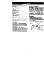
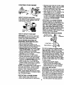
ATTACHING SHIELD
WARNING:
The shield must be prop
edy installed. The shield provides par.
tial protection from the risk of thrown
objects to the operator and others anc
is equipped with a line limiter which
cuts excess line to the proper length.
WARNING:
The line limiter (on un•derside of shield) is sharp and can cut
you.
WARNING:
• Remove wing nut from shield.
• Insert bracket into slot as shown.
• Pivot shield until bolt passes througl"
hole in bracket.
• Securely tighten wing nut onto bolt.
ASSEMBLY
WARNING: If received assembled,
repeat all steps to ensure your unit is
properly assembled and all fasteners
are secure.
ADJUSTING THE HANDLE
Shield
'__
WARNING: Make sure unit is properly
assembled and all fasteners are secure.
• Loosen the wing nut on the handle.
• Rotate handle to the upright position.
4
_
Slot
Bracket
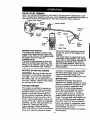
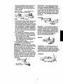
KNOW YOUR TRIMMER
READ THIS OPERATOR'S MANUALAND SAFETY RULES BEFORE OPERATLNGYOUR
UNIT. Compare the illustrations with your unit to familiarize yourself with the location of
the various controls and adjustments. Save this manual for future reference.
Engine Stop Switch
Starter
Rope
_
Assist Handle
Trimmer
Head
/
Cap
Throttle
Trigger
Choke
Primer
Bulb
Muffler
Une
Limiter
Blade
Spark Plug
ENGINE STOP SWITCH
The engine stop switch is used to stop
engine. Push and hold the engine stop
switch in the STOP or OFF position until
the engine has fully stopped.
PRIMER BULB
The primer bulb removes air from the
fuel lines and fills them with fuel. This
allows you to start the engine with fewer pulls on the starter rope. Activate
BEFORE
STARTING
ENGINE
WARNING:
Be sure to read the fuel
information in the safety rules before
you begin. If you do not understand
the safety rules, do not attempt to fuel
your unit. Call the 1-800 number listed
on the front of this manual.
FUELING ENGINE
This engine is cert'_ed to operate on
unleaded gasoline. Before operation,
gasoline must be mixed with a good
quality 2-cycle air-cooled engine oil.
We recommend Craftsman brand oil.
Mix gasoline and oil at a ratio of 40:1
(A 40:1 ratio is obtained by mixing 3.2
ounces of oil with 1 gallon of unleaded
gasoline). DO NOT USE automotive oil
or boat oil. These oils will cause
engine damage. When mixing fuel,
follow instructions printed on container.
Once oil is added to gasoline, shake
the primer bulb by pressing it and allowing it to return to its original form.
CHOKE
The choke helps to supply fuel to the
carburetor during starting. This allows
you to start a cold engine. Achvate the
choke by moving the choke lever to
the Full Choke position. After the engine has started, move knob to the Off
Choke position.
container momentarily to assure that
the fuel is thoroughly mixed. Always
read and follow the safety rules
relating to fuel before fueling your unit.
IMPORTANT
Experience indicates that alcohol
blended fuels (called gasohol or using
ethanol or methanol) can attract moisture which leads to separation and
formation of acids during storage.
Acidic gas can damage the fuel system of an engirte while in storage.
To avoid engine problems, empty fuel
system before storage for 30 days or
longer. Drain gas tank, start engine and
let it run until fuel lines and carburetor
are empty. Use flesh fuel next season.
Never use engine or carburetor cleaner products in the fuel tank or permanent damage may occur.
See the STORAGE section for additional information.
5
STARTING
YOUR
ENGINE
Switch
HOW TO STOP YOUR UNIT
Push and hold the engine stop switch
in the STOP or OFF position until the
unit has fullystopped.
Choke Lever
Primer
Bulb
• Squeeze and hold the throttle trigge_
Keep throttle _gger fully squeeze
until the engine runs smoothly.
• Sharply pull starter rope until engin
runs, but no more than 5 pulis.
• Allow engine to run 15 seconds, the_
move choke lever to Off Choke.
• If engine fails to start in 5 pulls, pull sta=
er rope 5 more pulls. If engine still do_,
not run, it is probably flooded. Procee(
to Starting a Rooded Engine.
STARTING A FLOODED
Flooded engines can be started by
moving choke lever to Off Choke; then
_uUllrope to clear engine of excess
el. This could require pulling starter
rope many times depending on how
badly unit is flooded. If unit still doesn'
start, refer to TROUBLESHOOTING
CHART or call the 1-800 number found
on the front of this manual.
OPERATING
HOW TO START YOUR UNIT
position while continuing to squeeze
trigger for 30 second warm up.
NOTE: If the engine fails to start after 6
pulls (at Half Choke), check to make
sure the choke lever is in the proper
position. Then, repeat the above
steps. If the engine still does not start,
it is probably flooded. Proceed to Starting a Flooded Engine.
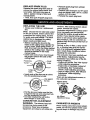
RESTARTING
INSTRUCTIONS
Cut from your
right to your left.
WARNING:
The trimmer head will
turn while starting the engine. A hot
muffler can cause serious burns.
COLD ENGINE STARTING OR
STARTING AFTER REFUELLING
• Set unit on flat surface.
• Move engine stop switch to On.
• Slowly press the pdmer bulb 6 times.
• Move choke lever to Full Choke.
• Squeeze and hold the throttle trigger.
Keep throttle trigger fully squeezed
unUI the engine runs smoothly.
• Sharply pull starter rope until engine
attempts to run or 5 times.
• Move choke lever to Half Choke.
• Sharply pull starter rope until the engine runs, but no more than 6 pulls.
• Continue to _iqueeze tdooer and allow
engine to run for 5 to 10 seconds.
• Move choke lever to the Off Choke
ENGINE
Eye
Protection
long Pants -._
Heavy Shoes --_
Do not run engine at a higher speed
than necessary. The cutting line will cut
efficiently when engine is run at less
than full throttle. At lower speeds there ie
less engine noise and vibration. The cutting line will last longer and will be less
likely to "weld" onto the spool. Always
release throttle trigger and allow engine
to return to idle speed when not cutting.
To stop engine:
• Release the throttle trigger.
• Push and hold the engine stop
switch ir_the.STOP or OFF position
until the _nglne has fully stopped.
CUTTING
METHODS
WARNING:
Use minimum speed and
do not crowd line when cutting around
hard objects (rock, gravel, fence posts,
etc.), which can damage the trimmer
head, become entangled in the line, or
be thrown causing a serious hazard.
• The tip of the line does the cutting.
You will achieve the best perform-
A WARM ENGINE
• Move engine stop switch to On.
• Move the choke lever to Half Choke.
6
ance and minimum line wear by not
crowding the line into the cutting
area. The right and wrong ways are
shown below.
Tip of the Line
Does The Cutting
Line Crowded Into
Work Area
SCALPING - The scalping technique
removes unwanted vegetation. Hold
the bottom of the trimmer head about 3
in. (8 cm) above the ground and at an
angle. Allow the tip of the line to strike
the ground around trees, poets, monuments, etc. This technique increases
line wear.
'
• The line will easily remove grass and
weeds from around walls, fences,
trees and flower beds, but it also can
cut the tender bark of trees or shrubs
and scar fences. To help avoid damage especially to delicate vegetation
or.trees with tender bark, shorten line
to 4-5 in. (10-13 cm) and use at less
than full throttle.
• For trimming or scalping, use less
than full throttle to increase line life
and decrease head wear, especially:
• During light duty cutting.
• Near objects around which the line
can wrap such as small posts,
trees or fence wire.
• For mowing or sweeping, use full
throttle for a good clean job.
MOWING - Your trimmer is ideal for
mowing in places conventional lawn
mowers cannot reach. In the mowing
position, keep the line parallel to the
ground. Avoid pressing the head into
the ground as this can scalp the
ground and damage the tool.
WARNING:
Always wear eye protection. Never lean over the trimmer head.
Rocks or debris can ricochet or be
thrown into eyes and face and cause
blindness or other serious inju_.
TRIMMING - Hold the bottom of the
trimmer head about 3 in. (8 cm) above
the ground and at an angle. Allow only
the tip of the line to make contact. Do
not force trimmer line into work area.
SWEEPING - The fanning action of
rotating line can be used for a quick
and easy clean up. Keep line parallel
to and above the surfaces being swept
and move the tool from side to side.
Sweeping
Trimming
7
_._,
....
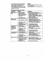
MAINTENANCE
SCHEDULE
CARE & MAINTENANCE
TASK
WHEN TO PERFORM
Check for Loose fasteners and parts
Before each use
Check for damaged or worn parts
Clean unit and labels
Before each use
Clean air filter
Every 5 hours of operation
Yearly
Replace spark plug
After each use
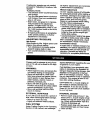
GENERAL RECOMMENDATIONS
The warranty on this unit does not cover items that have been subjected to
operator abuse or negligence. To receive full value from the warranty,the
operator must maintain unit as instructed in this manual. Various adjustments
will need to be made periodicallyto
properly maintain your unit.
CLEAN UNIT & LABELS
CHECK FOR LOOSE
Cleaning the air filter:
A dirty air filter decreases engine performance and increases fuel consumption and harmful emissions. Always
clean after every 5 hours of operation.
• Clean the cover and the area around
it to keep dirt and debris from falling
into the carburetor chamber when
the cover is removed.
• Remove parts as illustrated.
• Wash the filter in soap and water.
• Allow filter to dry.
• Replace parts.
Choke
FASTENERS
AND PARTS
• Spark Plug Boot
• Air Filter
• Housing Screws
• Assist Handle Screws
• Shield
CHECK FOR DAMAGED OR
WORN PARTS
Refer replacement of damaged/worn
parts to your Sears Service Center.
• Engine Stop Switch - Ensure switch
functions properly by holding the
switch in the "Stop" position. Make
sure engine stops; then turn sw'Rch
on, restart engine, and continue.
• Fuel Tank - Do not use unit if fuel tank
shows signs of damage or leaks.
• Shield - Discontinue use of unit if
debris shield is damaged.
• Clean the unit using a damp cloth
with a mild detergent.
• Wipe off unit with a clean dry cloth.
CLEAN AIR FILTER
Do not clean flter in gasoline or other
flammable solvent to avoid creating a
fire hazard or producing harmful evaporative emissions.
.EXit SlOt
P_,\i_
_
Choke
___ ._
"'w'_
Air
Filt.ee_
Fiiler
Cover
Corners
REPLACE SPARK
PLUG
Replace the spark plug each year to
ensure the engine starts easier and
runs better. Set spark plug gap at
.025 in. Ignition timing is fixed and
nonadjustable.
• Twist, then pull off spark plug boot.
• Remove spark plug from cylinder
and discard.
• Rap[ace with Champion CJ-8Y spark
plug and tighten with a 3/4 in. socket
wrench (10-12 ft.-Ibs).
• Reinstall the spark plug boot.
REPLACING
THE LINE
• Always use Craftsman replacement
line.
Note: Choose the line size best suited
for the job at hand. Green colored line
is designed for cutting grass, red line
for grass and small weeds. The black
colored line is designed for cutting
larger weeds and light brush.
• Before inserting the line into the
holes in the cutting head, identify the
proper holes. When us=rigGreen, or
Red, line insert into the holes marked
small on the cutting, head. Black line
should be inserted m the holes
marked large.
• Insert both ends of your line through
the proper holes in the side of the
cutting head.
cautions. After making mixture adjustments, recheck idle speed.
Carburetor adjustment is critical and if
done improperly can permanently
damage the engine as well as the carburetor. If you require further assistance or are unsure aboLd performing
this procedure, call our customer assistance help line found on the front of
this manual.
Positionin9
holes
Tunnel
holes
• Insert ends of the line one at a time
thru the positioning tunnels.
_Line
against
Old fuel, a dirty air filter, a dirty fuel filter, or flooding may give the impression of an impropedy adjusted carburetor. Check these conditions before
adjusting the carburetor.
The carburetor has been carefully set
at the factory. Adjustments may be
necessary if you notice any of the following conditions:
• Engine will not idle. See =Idle Speed"
under adjusting procedure.
• Engine dies or hesitates instead of
accelerating. See =Acceleration
Check" under adjusting procedure.
• Loss of cutting power. See =Mixture
Adjustment" under adjusting
procedure.
There are two adjustment screws on
the carburetor as shown.
Mixture Screw
with LimiterCap
• Pull the line and make sure the line
is against the hub and extended fully
thru the positionin_ tunnels.
• Correctly intalled hne will be the
same length on both ends.
CARBURETOR
Idle
Adjustment Screw
ADJUSTMENT
WARNING:
The trimmer head will
be spinning during most of this
procedure. Wear your protective
equipment and observe all safety pre-
CARBURETOR PRESETS
When making carburetorpreset adjustmerits, do not force plastic limitercaps
beyondstops or damage may occur.
9
If carburetor presets are not needed,
proceed to "Adjusting Procedure, Idle
Speed."
TO adjust presets:
• Turn mixture screw counterclockwise
until it stops.
• Turn the idlespeed screw clockwise
until it stops. Now turn counterclockwise 4-1/2 turns.
• Start motor, cut grass for 3 minutes,
and proceed to the adjustment
section. If engine does not start,
refer to troubleshooting chart or call
the 1-800 number found on the front
of this manual.
• If engine performance is acceptable
at the preset positions, no further
adjustment is necessary.
ADJUSTING
PROCEDURE
Idle Speed
Allow engine to idle. Adjust speed until
engine runs without stalling.
° Turn clockwise to increase engine
speed if engine stalls or dies.
• Turn counterclockwise to decrease
speed.
Prepare unit for storage at end of season or if it will not be used for 30 days
or more.
WARNING:
• Allow engine to cool, and secure the
unit before stodng or transporting.
• Store unit and fuel in a well ventilated area where fuel vapors cannot
reach sparks or open flames from
water heaters, electric motors or
switches, furnaces, etc.
• Store unit with all guards in place.
Position unit so that any sharp object
cannot accidentally cause injury.
• Store unit and fuel well out of the
reach of children.
EXTERNAL
SURFACES
If your unit is to be stored for a period of
time, clean it thoroughly before storage.
• Store in a clean dry area.
• Lightly oil external metal surfaces.
FUEL
SYSTEM
Under Fueling Engine in the Operating
Section of this manual, see message
No further adjustments are necessary
if performance is satisfactory.
Mixture Adjustment
DO NOT operate engine at full throttle
for prolonged periods while making adjustments. Damage to the engine can
occur. Replace cutting line with a new
piece of line, and cut some grass.
Based on performance while cutting,
turn the mixture adjustment in
t/16-turn increments as follows:
• Clockwise until the engine has good
power while cutting with no hesitation.
Do not adjust by sound or speed, but
judge by how well the engine performs while cutting.
• Counterclockwise if engine has speed
but dies or lacks power while cutting.
After completing adjustments, check
for acceleration. Reset if necessary.
Acceleration Check
If engine dies or hesitates instead of accelerating, turn mixture adjustment court
terclock_se until you have smooth acceleration. Recheck and adjust as
necessary for acceptable performance.
labeled IMPORTANTregarding the use
of gasohol in your engine.
Fuel stabilizer is an acceptable alternative in minimizing the formation of
fuel gum deposits during storage. Add
stabilizer to the gasoline in the fuel
tank or fuel storage container. Follow
the mix instructions found on stabilizer
container. Run engine at least 5 minutes after adding stabilizer.
CRAFTSMAN 40:1,2-cycle engine oil
(air cooled) is already blended with
fuel stabilizer. If you do not use this
Sears oil, you can add a fuel stabilizer
to your rue! tank.
INTERNAL
ENGINE
• Remove spark plug and pour I teaspoon of 40:1, 2-cycle engine oil (air
cooled) through the spark plug opening. Slowly pull the starter rope 8 to
10 times to distribute oil.
• Replace spark plug with new one of
recommended type and heat range.
• Clean air filter.
10
• Check entire unit for loose screws,
nuts, and bolts. Replace any damaged, broken, or worn parts.
• At the beginning of the next season,
use only fresh fuel having the proper
gasoline to oil ratio.
TROUBLESHOOTING
OTHER
• Do not store gasoline from one season to another,
• Replace gasolinecan if it startsto rust.
CHART
TROUBLE
CAUSE
REMEDY
Engine will not
start.
• Engine flooded.
Fueltankemp_
_Sparkplugnotfiring.
• See =Starting Instructions."
• Fill tank with correct fuel mixture.
• Install new spark plug.
Check for dirty fuel filter; replace.
Check for kinked or split fuel line;
• Fuel not reaching
carburetor.
I. repair
replace.
ContactorSears
Service.
• Compressionlow.
Engine will not
idle properly.
• Idle speed set too low. • Adjust idle speed screw
Engine will not
accelerate,
lacks power,
or dies under
a load.
• Air filter dirty.
• Spark plug fouled.
Engine smokes
excessively.
Engine runs hot
clockwise to increase speed.
• Idle speed set too high. • Adjust idle speed screw counterclockwise to reduce speed.
• Carburetor requires
• See "Carburetor Adjustments."
adjustment.
• Crankshaft seals worn. • Contact Sears Service.
• Contact Sears Service.
• Compression low.
• Carburetor requires
• Clean or replace air filter.
• Clean or replace spark plug
and re-gap,
• See =Carburetor Adjustments."
adjustment.
• Carbon budd up.
• Compression low.
• Contact Sears Service.
• Contact Sears Service.
Choke partial!y on.
Fuel mixture incorrect.
• Adjust choke.
• Empty fuel tank and refill with
correct fuel mixture.
• Air filter dirty.
* Carburetor requires
adjustment.
• Clean or replace air filter.
• See "CarburetorAdjustments."
• Fuel mixture incorrect.
• See "Fueling Your Unit."
• Spark plug incorrect.
Carburetor requires
adjustment
• Carbon build up.
• Replace with correct spark plug.
See "Carburetor Adjustments."
• Contact Sears Service.
11
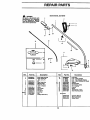
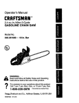
REPAIR PARTS
WARNING
SEARS MODEL 358.796090
All rel_lrs , adjustmlntl
and
minteflance
not desarlbed
4
2
in the Operator's
Mmlual
must be performed by quailfled service personnel.
I
1
I
3
5
12
Ref.
Part No.
53O095321
53OO69496
3
4
5
6
530015610
53O029445
530094847
53O069666
7
8
9
10
530015814
530052286
530401992
530095176
13
71-85640
Description
Ref.
14
15
Drive Shaft Housing
Assist Handle I_t
pnd. 3, S, 21)
Nut
Drive Shaft Gdp
Qamp-Ass_
Shield l_t Ass'y.
(In4d. #7&8)
Screw
Une Limiter
V_ngnut
Flex Shaft
Dust Cup
Bolt
Cutting Head Ass'y.
"
16
17
18
19
2O
21
22
23
Part No.
530095653
71-85641
71-85628
71-85629
530016296
530016297
530031159
530o69252
530015768
530015774
530047329
530047467
Description
HubAss',/.
Une - Green {Grass)
Line - Red (Grass& Weeds)
Une - Black (Weeds& It. Brush)
Washer
Nut-Shoulder
HexWrench(5/32)
Kit-T-Handle
Locknut
Screw
Throttle Hsg, Ass'y,
ShaftWarning Decal
Not Shown
530087756
952701570
530O54O49
12
Operator Manual
Shaft _ion
Shield Decal
REPAIR PARTS
2
3
5
6
10
12
KIT
lOT
KIT
Carburetor
Repair Kit
KIT
KIT
Gasket
Diaphragm
Kit
KIT
(KIT=Contents)
I
17
16
Ref.
1,
2.
3,
4.
5.
Part No.
53(X)471_
530015826
530027t_3
530016080
53006_486
Descdl_lon
F_VneelAss',/.
_/asher-Ret
Odve Coupling
_ew-Staner
Pulley
Starter Pulley IGt
Ref
16.
t7.!
952701612
5S006_37
18.
19.
5,30038403
(_. 4)
6.
7.
8.
9.
10.
11.
12.
13.
14.
15.
530042065
530015496
530_7523
530049488
,53OO699O7
53006_810
530015767
530015768
530015769
530015770
Part No.
Starter Sl_ng
Scow--Retaining
Pulley Retainer
Sta_teI"Handle
Ropel_t
Fan Housing I_
Screw-Pinch Qamp
Locknut-Pinch Clamp
Screw-Fan Housing
Screw-Fan Housing
13
Dem'IpUo.
,Spark/vrestor
10t
Cart_retor
RepairKit
(Krr=contents)
Gasket,_aphragm
UmiterCap
T
16
REPAIR PARTS
1
2
3
4
'
56
8
40
41
9
10
11 _
12
51
28
52
5,"
I
3555
363738
3920
44
"1 Part No.
'J.
2.
3.
4.
5.
6.
7.
8.
9.
10.
11.
oee_
5,10015773 Screw-Air Fdter
Cover
530_7529 F'dterCover
530_7530
_r Fdter
,53OO15849 Screw
530015852 Spacer-Choke
530015254 Nasher
530038915 3hoke Shutter
530037930 Air Filter Plate
Fuel Line IQt
Prinlar/Tenk
Tank/Purge
_47
53O014362
Fuel Pick-up Ass',/.
Carburetor Wat0NA219
Refo
part No.
20. 5,30O15789 Retaking Ring21. 580010945
22.
23.
24.
5_0015126
580015771
6.._0 f5775
25. i 530037498
26.
27.
28.
530001624
530015772
5,,'_0014016
530019156
530014347
530047577
530019154
16.
17.
18.
530027593
53OO27594
530O140O4
19
530010960¸
Carburetor Gasket
Fuel Cap ASS_.
Shroud & Tank Ass'y.
Crankcase/Shroud
Gasket
Reed Vak,e
Reed Stop
C'case/Crankabaft
Ass'y. (Incl. 20. 21 &
2e)
Connecting Rod
Crankshat_
Cranksh=ft Ass'y.
Screw
Key
Seres-Throttle
Cable
Thrett[e Cable
Ass',/.
Screw-Cyclindor
Screw
(Ind. _39)
)29.
530015717
30.
31.
530047541
530016064
(Ind. Um_r caps)
12.
13.
14.
15.
041414_on
32. I 530015162
33. ! 530O25875
34. 530019178
35. i 530069899
36.
37.
38.
39.
530032103
530015787
530019158
530032102
Sorew-Muffler
Guard
:Muffler Guard
Screw
,
Piston Pin Ret. ,.
Piston Ring
Cylinder Gasket
Piston Fat
(Ind. 32, 33 & Pin}
Inner Bearing
Retaining Ring
Cra_P.sh_t Se_d
Outer Beadng
/L_s'y.
14
Ref
Part No.
40.
_4
41.
42.
550016091
5S0069310
44.
45.
!
DeecHpUon
Bulb A.ss'y.
Sorew-Pdmar B
Muffler
MufflerSp_ng
Cylinder
K=t
Cham_on SparkRug
4s.! 580039134
47.
580015816
48.
58OO69276
50.
51.
52.
53.
54.
55.
5_00157(KI
,5_0(_7546
580027547
58OO27545
58003830_
5_0027959
530053346
(cJ-_
Ignition Module
Sorew-lgeltion
Modu/e
Engine Gasket I
(Incl. 12,15 & ._
Screw
Switch Insulator
Lead Wire
Switch Ramp
Switch Button
Sw_tch Spdng
Heat Shield/Air
Not Shown
530049927
5SOOS4047
Instruction Dec=
Shroud Decal
For in-home major brand repair service:
Call 24 hours a day, 7 days a week
1-800-4-MY-Home s" (1-800-469-4663)
Para pedir servicio de reparacibn a domicilio - 1-800-676-5811
In Canada for all your service and parts needs call
- 1-800-665-4455
Au Canada pour tout le service ou les pi_ces
For the repair or replacement parts you need:
Call 7 am - 7 pro, 7 days a week
1-800-366-PART
(1-800-366-7278)
Para ordenar piezas con entrega a domicilio - 1-800-659-7084
For the location of a Sears Parts and Repair Center in your area:
Call 24 hours a day, 7 days a week
1-800-488-1222
For information on purchasing a Sears Maintenance Agreement
or to inquire about an existing Agreement:
Call 9 am - 5 pm, Monday - Saturday
1-800-827-6655
The Service Side of Sears =`