1
®
THEQUALITY
GOESINBEFORE
THENAMEGOESON
................
_::_i_i_iii,:_iiiiiii!:iiiiii
_i_i_:_iiiiiiiiiii_iiiiiiii_iiiiiii_ii_iiii
Return
the
Product
Registration
Card
and your
VCR could
be
FREE!
WARNING:
TO
REDUCE
REMOVE
IHE
RISK
COVER
(OR
PARTS INSIDE. REFER
OF
ELECTRIC,
BACK).
NO
TO QUALIFIED
USER
DO
NOT
SERVICEABLE
SERVICE
TO PREVENT FIRE OR SHOCK HAZARDS,
THIS PRODUCT TO RAIN OR MOISTURE.
The lightning flash
triangle, is intended
"dangerous voltage"
sufficient magnitude
SHOCK
PERSONNEL.
DO NOT EXPOSE
with arrowhead symbol, within an equilateral
to alert the user to the presence of uninsulated
within the product's enclosure that may be of
to constitute a risk of electric shock to persons.
The exclamation point within an equilateral triangle is intended to
alert the user to the presence of important operating and maintenance
(servicing) instructions in the literature accompanying the appliance.
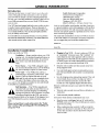
Safety Tips
Regulatory
Refer to the "Safety Tips" section of this operating guide
for important safety considerations.
This equipment has been tested and found to comply with
the limits for a Class B digital device, pursuant to Part 15
of the FCC Rules. These limits are designed to provide reasonable protection against harmful interference in a residential installation. This equipment generates, uses and can
radiate radio frequency energy and, if not installed and
used in accordance with the instructions, may cause harmful interference to radio communications. However, there is
Note to Cable TV System Installer
This reminder is provided to call the cable TV system installer's attention to Article 820-40 of the NEC that provides guidelines for proper grounding and, in particular,
specifies that the cable ground shall be connected to the
grounding system of the building, as close to the point of
the cable entry as practical.
Power-Cord Polarization
This product is equipped with a polarized alternatingcurrent line plug (a plug having one blade wider than the
other.) This plug will fit into the power outlet only one
way. This is a safety feature. If you are unable to insert the
plug fully into the outlet, try reversing the plug. If the plug
should still fail to fit, contact your electrician to replace
your obsolete outlet. Do not defeat the safety purpose of
the polarized plug by altering it in any way.
CAUTION
TO PREVENT ELECTRIC SHOCK, MATCH WIDE
BLADE OF PLUG TO WIDE SLOT, FULLY INSERT.
ATTENTION
POUR I_VITER LES CHOCS I_LECTRIQUES, INTRODUIRE LA LAME LA PLUS LARGE DE LA FICHE
DANS LA BORNE CORRESPONDANTE DE LA PRISE
ET POUSSER JUSQU'AU FOND.
Information
no guarantee that interference will not occur in a particular
installation. If this equipment does cause harmful interference to radio or television reception, which can be determined by turning the equipment off and on, the user is
encouraged to try to correct the interference by one or more
of the following measures:
•
Reorient or relocate the receiving antenna.
•
Increase the separation between the equipment and
receiver.
•
Connect the equipment into an outlet on a circuit
different from that to which the receiver is connected.
•
Consult the dealer
technician for help.
or an experienced
radio/TV
CAUTION: Do not attempt to modify this product in any
way without written authorization from Zenith Electronics
Corporation. Unauthorized modification could void the
user's authority to operate this product.
This class B digtal apparatus meets all requirements of the
Canadian Interference-Causing Equipment Regulations.
"Ce appareil num6rique de la class b respecte toutes les
exigences du R_gulament sur le mat6riel brouillier du
Canada."
Copyright © Zenith Electronics Corporation 1996
2
VCRWARN[
SAFETY TIPS
Important
safeguards
for you and your
new product
Your product has been manufactured
and tested with your safety in mind. However, impropc_ use can result in potential electrical
shock or fire hazards. To avoid defeating the safeguards that have been built into your new product, please read and observe the
following safety points when installing and using your new product, and save them for future reference.
Observing the simple precautions
discussed in this section of the operating
safe operation that are built into your new product.
1.
2.
Read Instructions
All the safety and operating instructions
read before the product is operated.
Follow Instructions
All operating
lowed.
o
.
5.
6.
7.
8.
and use instructions
9.
should be
not recommended
as they may cause
by thc
hazards.
Slots and openings
in the cabinet are provided
for
ventilation
and to ensure reliable operation
of the
product
and to protect it from overheating,
and
these openings
must not be blocked
or covered.
The
openings
should never be blocked
by placing
the
product on a bed, sofa, rug, or other similar surface. This product
should not be placed in a built-in
installation
such as a bookcase
or rack unless
should be re-
Heed Warnings
All warnings on the product and in the operating
structions should be adhered to.
Attachments
Do not use attachments
product manufacturer
and
10. Ventilation
should be fol-
Retain Instructions
The safety and operating instructions
tained for future reference.
guide can help you get many years of enjoyment
in-
proper ventilation
instructions
have
Cleaning
Unplug this product from the wall outlet before
cleaning. Do not use liquid cleaners or aerosol
cleaners. Use a damp cloth for cleaning.
Water and Moisture
Do not use this product near water -- for example,
near a bath tub, wash bowl, kitchen sink, or laundry
tub, in a wet basement, or near a swimming pool.
11. Power
is provided
or the manufacturer's
been adhered
to.
Sources
This product should be operated
only from the type
of power source indicated on the marking
label. If
you are not sure of the type of power supply to
your home, consult your product
dealer or local
power company.
For products
intended
to operate
from battery power,
or other sources,
refer to the
operating
instructions.
Accessories
Do not place this product on an unstable cart,
stand, tripod, bracket, or table. The product may
fall, causing serious injury to a child or adult, and
serious damage to the product. Use only with a
cart, stand, tripod, bracket, or table recommended
by the manufacturer,
or sold with the product. Any
mounting of the product should follow the manufacturer's instructions,
and should use a mounting
accessory recommended
by the manufacturer.
12.
Line-Cord
Polarization
This product
is equipped
with a polarized
alternating-current
line plug (a plug having one blade
wider than the other). This plug will fit into the
power outlet only one way. This is a safety feature.
If you are unable to insert the plug fully into the
outlet, try reversing
the plug. If the plug should
still fail to fit, contact
your electrician
to replace
your obsolete
outlet. Do not defeat the safety purpose of the polarized
plug.
Transporting
Product
A product and cart combination should be moved
with care. Quick stops, excessive force, and uneven
surfaces may cause the product and cart combination to overturn.
13. Power-Cord
Protection
Power-supply
cords should be routed so that they
are not likely to be walked on or pinched
by items
placed upon or against them, paying
particular
attention to cords at plugs, convenience
receptacles,
and the point where they exit from the product.
PORTABLE CART WARNING
ENGSAF4
3
SAFETY TIPS
14. Outdoor
Antenna Grounding
If an outside antenna or cable system is connected
to the product, be sure the antenna or cable system
is grounded so as to provide some protection
against voltage surges and built-up static charges.
Article 810 of the National Electrical Code
(U.S.A.), ANSI/NFPA
70 provides information
with regard to proper grounding of the mast and
supporting structure, grounding of the lead-in wire
to an antenna discharge unit, size of grounding conductors, location of antenna-discharge unit,
connection to grounding electrodes, and requirements for the grounding electrode.
EXAMPLE OF GROUNDING ACCORDING TO
NATIONAL ELECTRICAL CODE INSTRUCTIONS
18. Object
and Liquid Entry
Never push objects of any kind into this product
through openings as they may touch dangerous voltage points or short-out parts that could result in a
fire or electric shock. Never spill liquid of any kind
on the product.
19. Servicing
Do not attempt to service this product yourself as
opening or removing covers may expose you to dangerous voltage or other hazards. Refer all servicing
to qualified service personnel.
20. Damage Requiring Service
Unplug this product from the wall outlet and refer
servicing to qualified service personnel under the
following conditions:
a.
If the power-supply
cord or plug is damaged.
Antenna Lead in Wire
b. If liquid has been spilled, or objects have fallen
into the product.
c.
Ground
(NEC Section 810-20)
/'/
NEC - NATIONAL
ELECTRICAL
!
Antenna
Discharge Unit
Ground Clamps
Electrode System (NEC
Power
Art 250,Service
Part H)Grounding
CODE
15. Lightning
For added protection for this product (receiver) during a lightning storm, or when it is left unattended
and unused for long periods of time, unplug it from
the wall outlet and disconnect the antenna or cable
system. This will prevent damage to the product
due to lightning and power-line surges.
16. Power Lines
An outside antenna system should not be located in
the vicinity of overhead power lines or other electric light or power circuits, or where it can fall into
such power lines or circuits. When installing an outside antenna system, extreme care should be taken
to keep from touching such power lines or circuits
as contact with them might be fatal.
17. Overloading
Do not overload wall outlets and extension cords as
this can result in a risk of fire or electric shock.
ENGSAF4
has been exposed
to rain or water.
d. If the product does not operate normally by following the operating instructions. Adjust only
those controls that are covered by the operating
instructions as an improper adjustment of other
controls may result in damage and will often require extensive work by a qualified technician
to restore the product to its normal operation.
Grounding Conductors
(NEC Section 810-21)
_
If the product
e.
If the product has been dropped
has been damaged.
or the cabinet
f.
If the product exhibits
formance.
change
a distinct
in per-
21.
Replacement
Parts
When replacement
parts are required,
be sure the
service technician
has used replacement
parts specified by the manufacturer
or have the same
characteristics
as the original part. Unauthorized
substitutions
may result in fire, electric
shock, or
other hazards.
22.
Safety Check
Upon completion
of any service or repairs
to this
product,
ask the service
technician
to perform
safety checks to determine
that the product
is in
proper operating
condition.
23.
Wall or Ceiling
Mounting
The product
should be mounted
to a wall
only as recommended
by the manufacturer.
24.
or ceiling
Heat
The product
should be situated away from heat
sources such as radiators,
heat registers,
stoves, or
other products
(including
amplifiers)
that produce
heat.
SAFETY
WARNINGS
SAFETY
TIPS
...................................
..........................................
2
3
t.lock Menu .............
How to Set Clock .......................................
10
16
Timer Menu ...........................................
How to Use Timer .......................................
16
16
Setup Menu ............................................
Audio Menu ...........................................
17
17
WATCHING TV THROUGH VCR .......................
VCR is Turned Off ......................................
VCR Is Turned On and You Want to Select Channels at TV .....
VCR Is Turned On and You Want to Select Channels at VCR ....
Camcorder ls Connected to VCR ...........................
18
18
18
18
18
19
GENERAL INFORMATION ..............................
Introduction .............................................
6
6
Installation Considerations .................................
VCR Features Chart .......................................
6
7
BEFORE YOU OPERATE YOUR VCR .....................
8
1. Make Equipment Connections ............................
2. Connect the Power ......................................
3. Set Position of the CH3/CH4 Switch .......................
8
8
8
4. Select Language for VCR Menus/Displays ...................
5. Set Date and Time for Clock ..............................
8
8
PLAYING TAPES
Automatic Playback (No Safety Tab) ........................
19
6. Select Tuning Band for VCR .............................
7. Use Auto Channel to Find Channels ........................
8. Use CH. ADD/DEL to Create Favorite Channels ..............
9
9
9
Manual Playback (Has Safety Tab) .........................
Unloading the Cassette from the VCR .......................
19
19
9. Select Other Menu Options ...............................
9
19
19
19
.....................................
10
Auto/Manual Tracking Adjustment .........................
Real-Time Tape Counter .................................
Pause/Forward/Reverse Slow-Motion Video ..................
Connections Without a Cable Box ..........................
Connections With a Cable Box .............................
10
10
Tape Rewind and Fast Forward ............................
Reverse/Forward Search and Jet Search ......................
19
19
Audio/Video
11
Index Search ...........................................
19
Accessory Audio/Video (A/V) Connections to VCR ............
11
INSTANT RECORDING ................................
20
FRONT PANEL CONTROLS AND DISPLAYS .............
Items on the Front Panel ..................................
12
12
Recording What You Are Watching On TV ..................
Recording By Using Preset Time Periods ....................
20
20
LED Front Panel Indicators ................................
12
Recording One Program While Watching Another Program .....
20
VCR Status Displays .....................................
VCR Status Display Operation .............................
13
13
TIMER-CONTROLLED
21
VCR Status Display Options ...............................
13
REMOTE CONTROL SC2105 ...........................
14
Remote Control Operation .................................
14
Remote Control Keys ....................................
Installing Batteries .......................................
14
14
VCR MENU OPERATIONS
.............................
Available Menus ........................................
15
15
Basic Menu Operation ....................................
How to Access Menus ....................................
15
15
AVISO PARA NUESTROS CL1ENTESDE HABLA HISPANA
Auto Daylight Savings Menu ..............................
15
YOUR ZENITH VCR WARRANTY
CONNECTIONS
FOR YOUR VCR .......................
(A/V) Connections
to TV ......................
RECORDING
...................
Recording While You Are Away ...........................
VCR Operation with Timer Turned Off or On .................
21
21
SERVICE INFORMATION
22
.............................
Before Calling for Service ................................
22
Automatic Video Head Cleaning ...........................
23
Cabinet Cleaning ........................................
23
RECOMMENDED
REPLACEMENT
ACCESSORIES
FOR YOUR VCR
PRODUCT REGISTRATION
CARD
GENERAL INFORMATION
Introduction
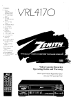
Welcome into the family ol Zenith Video Cassette Recorder
owners. This guide provides instructions on how to operate
your new VCR. It includes a section containing Safety Tips.
We urge you to read this publication carefully so that you will
receive full enjoyment from your new Zenith VCR for many
years to come.
Zenith Electronics
Corporation
Customer Service Department
1000 Milwaukee
Avenue
Glenview,
Telephone:
Mon-Fri,
Illinois 60025-2493
(847) 391-8752
8:00 a.m. - 4:30 p.m. Central
"l'inic
Your VCR has been designed and built to give you the very best
in quality, features and performance. There are thousands of
Zenith authorized video recorder service centers throughout the
U.S., Canada and Mexico who can attend promptly and effectively to ordinary service needs.
Send tile model number, serial number, and date of purchase
or original installation, with a full explanation of the problem
If you should have an unusual performance or service problem
that cannot be satisfactorily resolved by your Zenith authorized
video recorder service center, contact us at:
The model and serial numbers of your new VCR are located
on the VCR cabinet. For your future convenience
and protec-
and the service history. We will welcome the opportunity
to
look into your specific question or problem and to be of assistance in resolving it promptly.
tion, we suggest
that you record
these numbers
here:
Model No.
Serial No.
Installation
Considerations
Before you install your VCR...
•
Ventilation -- Proper ventilation keeps your VCR
running cool. Air circulates through perforations in
the back and bottom of the cabinet. Do not block
Plugging in Your VCR -an "unswitched"
AC power
outlets found on some video
supplying power to the VCR
these vents or you will shorten
VCR.
off. If the power to the VCR is interrupted for an extended
time, you will have to reset the clock in the VCR.
the life of your
Be sure to plug your VCR into
source. The "switched"
AC
equipment will not continue
once the equipment is turned
Power Source -- Your VCR is designed to operate on normal household current, 120 volt 60 Hertz
•
Keep the video recorder
strong magnetic fields.
AC. Do not attempt
•
Use only Zenith approved and recommended accessory
units with your Zenith video recorder to avoid potential
hazards.
•
Save the shipping carton and packing material. They will
come in handy if you ever have to ship your video recorder. For maximum protection, re-pack the video
recorder as it was originally shipped from the factory.
to operate it on DC current.
Power Cord -- Your VCR power cord has a
polarized plug as required by Underwriters'
Laboratories. It has one regular blade and one wide
blade and fits only one way into a standard electrical outlet. If the blades will not enter either way,
your outlet is very old and non-standard. A new outlet should
be installed by a qualified electrician.
Safe Operation
-- Your VCR is manufactured
usual stress caused by dropping or mishandling,
and
tested towith
yourfire,
safety
However,
unexposure
flood,
rain in
or mind.
moisture,
or accidental spilling of liquids into the VCR, can result in
potential electrical shock or fire hazards. If this happens, have
your VCR checked by a service technician before using it
again.
Please read and observe each safety point in the "Safety
Tips" section of this operating guide when installing and
using your VCR.
and video cassette
away from
Moisture condensation is apt to occur under the following
conditions:
•
When the video recorder
is moved
from a cold place to a
warm place.
•
Under extremely
In locations
humid conditions.
where moisture
condensation
may occur:
•
Keep the power cord plugged into an AC outlet and the
POWER switch set to ON. This will help prevent condensation from occurring.
•
When condensation
has occurred,
it will not evaporate
quickly once the power is switched on. Wait a few hours
for the video recorder to become dry before using the
video recorder.
V('RINI
R5
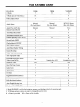
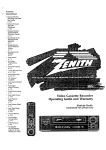
VCR FEATURES CHART
FEATURES
VR2106
VR4106
VR4206H F
X
N/A
N/A
N/A
X
X
Full Load/Quick Start
X
X
X
Auto Head Cleaner
X
X
X
Monaural
(No Audio Menu)
Monaural
(No Audio Menu)
MTS Hi-Fi Stereo
(Has Audio Menu)
Monaural
Monaural
Stereo
Remote Control SC2105
X
X
X
Auto/Manual
Band Select
X
X
X
Auto/Manual
Channel Search
X
X
X
181
181
181
Record Speeds SP/EP
X
X
X
Playback Speeds SP/LP/EP
X
X
X
Auto Playback System
X
X
X
Auto/Manual Digital Tracking
X
X
X
Instant Recording
X
X
X
X
X
X
X
X
X
N/A
X
Variable 1/6 to 1/32
X
Variable 1/6 to 1/32
Noise
Clear
Clear
Real-Time Tape Counter
X
X
X
Index Search
X
X
X
Speed Search
X
X
X
Jet Search
X
X
X
X
X
X
l-Year, 8-Event Timer
X
X
X
LED Front Panel Indicators
X
X
X
Auto Daylight Savings Time
X
X
X
Hook-up Cable (VCR to TV)
X
X
X
2-Heads
4-Heads (Special Video Effects)
Audio System
Audio/Video
(A/V) Jacks
Channel Capability (CATV & TV)
Timer-Controlled
Recording
Auto Tape Speed Adjust
Forward/Reverse Slow-Motion
Video (4-head VCR)
Pause/Still Video
English/Spanish/French
Menus
1. Model VR4206HF is used for the description, operation, and details provided in this operating guide.
2. VCR design and specifications are subject to change without prior notice.
X = Feature is provided
N/A = Feature is Not Available
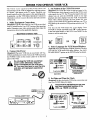
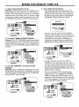
BEFORE YOU OPERATE YOUR VCR
1'his VCR is "menu" operated. In other words, features and
characteristics
of the VCR are adjusted by selecting options
on "menus" that appear on the TV screen. Therefore, you
should carefully review the menus in this operating guide.
In particular,
see the "VCR Menu Operations" section for
information on how to access the menus and select an item
on the menu.
1. Make Equipment
Connections
(Required) Typical connections for your VCR are provided
in the "Connections for Your VCR" section of this operating
guide. Determine your video system needs, then make the
connections shown on the applicable diagrams.
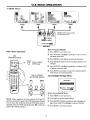
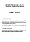
Back Panel of Stereo VCR
3.
Set Position
of the CH3/CH4
Switch
(Required)
The CH3/CH4 switch on the back panel of the
VCR determines which channel is used by the VCR to send
video signals to your TV. The TV must be tuned to the same
channel you set with the CH3/CH4 switch to see tape
playback and status displays from the VCR. To determine
which video channel provides the best picture for your
system, try the switch in CH3 position and tune your TV to
CH3; then try the switch in CH4 position and turn your TV
to CH4.
You may use the VCR menus for a test display. Press
TV/VCR on remote repeatedly until veR symbol appears
in the front panel display of the VCR. Press MENU on the
remote to see the main menu.
IN
[-- R- AUDIO-L --I-VIDEO
-I
VHFIUHF/CATV
5.,1®=,®1oo,®1
I®'"®1'"®1
w
2. Connect the Power
(Required) Plug your VCR into an unswitched 120 Vac,
60 Hz household power outlet. Turn on the VCR by pressing
the POWER switch on the remote control or on the front
__
c.3_c.,
OR
4. Select Language
CH3
[_ CH4
for VCR Menus/Displays
(Optional) Select the language (English, Spanish or French)
you want for VCR menus and status displays. See LANGUAGE SELECT option on the SETUP menu for details.
panel of the VCR.
f_--------_
power outlet. Otherwise, when the
Do
not is
plug
the VCR
switched
power
switched
off,into
the aVCR
turns
off. You may then have to reset the time
and date, and reprogram operational
features.
CLOCK
TIMER
[]
M
WALL
SWITCH
TUNINGBAND:
AUTOCHANNEL:
CH. ADD/DEL:
SOURCESELECT:
_
SETUP
AUDIO I
to select
II
tO adjust
[
To exit press r_rJ_
ON-SCREEN
DISPLAY:
BtOToseleCtexit
press[]
to__adjust
j
J
SETUP MENU WITH
LANGUAGE SELECT
HIGHLIGHTED
MAIN MENU
5. Set Date and Time for Clock
(Required) Set the clock in the VCR to the current date and
time. See CLOCK Menu for details.
any timer-controlled
features of the
lock e.g.
mustTIMER
be setrecordings.
before you can use
VCR,
_
[CLOCK
-O.
•
oG
i
TIMER SETUP AUOIO I
_
[]
to adju
to
select
I
/
st
L
To exit press r_r]_
I
J
TIME
:11:06AM
lltoselect
TO exit press
lilt°adj
ust
CLOCK MENU WITH
MONTHHIGHLIGHTED
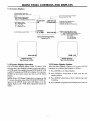
BEFORE YOU OPERATE YOUR VCR
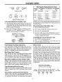
6. Select Tuning
Band
for VCR
(Optional) Set the tuning band of the VCR for the type of
program signal you have connected to the ANT IN jack on
the back of the VCR. Choose TV if you have an antenna
connected to the VCR. Choose CATV if you have a cable
system (with or without a cable box) connected to the VCR.
See TUNING BAND option on SETUP menu for details.
e
Select Other Menu
Options
• Your VCR adjusts the clock automatically for
Daylight Savings Time. Select OFF for this option
if you do not want your clock to be adjusted for
Daylight Savings Time. Refer to Auto Daylight
Savings Menu (Special Menu) for details.
Special Menu
CLOCK
TIMER
SETUP
[]
to select
I_
AUDIO
IPlto select
[] to adjust
To exit press
to adJust
To exit press
_
To exit press
SETUP MENU WITH
TUNING BAND
J
MAIN MENU
HIGHLIGHTED
• You may select the audio format (STEREO,
MONO or 2ND AUDIO) to be used when you record programs, if you have a stereo VCR. We recommend you set this option to STEREO for
recording most programs. Refer to the RECORD
MODE option on the AUDIO menu for details.
7. Use Auto Channel to Find Channels.
(Required) Use AUTO CHANNEL to find active channels
in your broadcast area. AUTO CHANNEL stores the active
channels in protected memory for access by using Channel
Up/Down. See AUTO CHANNEL option on SETUP menu
for details.
PLAYBACK MODE:
CLOCK
CLOCK
TIMER
[]
SETUP
To exit press
[]
to select
I
to adjust
I
_
[
To exit press _
To exit
MAIN MENU
8. Use CH. ADD/DEL
Channels
select
_ to adjust
To exit press
J
MENU
)
MAIN MENU
SETUP MENU WITH
AUTO CHANNEL
HIGHLIGHTED
)
Bto
AUDIO
I
to adjust
_,,
SETUP
AUDIO I
tO select
AUDK_
I
TIMER
You may select the audio format (HI-FI or
NORMAL) to be used when you play a tape, if
you have a stereo VCR. We recommend you set
this option to HI-FI for playback of most tapes.
Refer to the PLAYBACK MODE option on the
AUDIO menu for details.
to Create Favorite
(Optional) Use CH. ADD/DEL to change the list of active
channels found when using AUTO CHANNEL, so you can
create you own list of favorite channels. See CH. ADD/DEL
option on SETUP menu for details.
You may prevent the VCR status from being
shown on your TV by using the ON-SCREEN
DISPLAY option on the SETUP menu. We recommend you keep this option to ON to show the
VCR status whenever it is provided by the VCR.
Refer to the SETUP menu for details.
CLOCK TIMER SETUP AUDIOI
[]
tO select
I
to adjust
I
To exit press
MAIN MENU
_
)
In to adjust
To oxtt press
CLOCK
SETUP MENU WITH
CHANNEL ADD/DEL
HIGHLIGHTED
TIMER
SETUP
AUDIO
)il
[]
to select
to adjust
To exit press
_,.
MAIN MENU
B
to adjust
To exit
SETUP MENU WITH
ON-SCREEN DISPLAY
HIGHLIGHTED
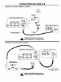
CONNECTIONS
(Required)
Connections
Without
a Cable
FOR YOUR VCR
Box
Antenna
\%%_///
\
%-,
Flat Wire
(300 ohm)
Back Panel of Stereo VCR
ANT
/
_
--f-VIDEO
-_
i®ou,®lo0,®l
I _
t[_H
_l
[_(_
IN
I"
_)l
_l
"I
IN
OUT
_j)[
TO
j
,_
(Required)
Connections
_
[|A])
""
_
\
!
|
-...
J
o,
' ,I /
Tv \'m_lP'J
This cable is provided_.__
with your VCR
Adaptor
OR
_,=_-=4_'" _
/
-- - --
/
,N ((''_
f--R-AUDIO-L
//
I1
U
300/75 ohmCable |TV
WallJack
\
,
Back Panel of Typical TV
•
\ ,_
_
--
_
TURN
OFFMAKING
POWER ANY
OR CONNECTIONS
UNPLUG VCR
BEFORE
With a Cable
Box
Back Panel of Typical TV
I-R'AUDIO'L
-T "VIDEO
7
(_ANT
Typical
Cable
CableTV
Wall Jack
Box
Back Panel of
oot
CABLE
A
1
.
i
This cable is provided
with your VCR.
_
TURN
OFFMAKING
POWER ANY
OR CONNECTIONS
UNPLUG VCR
BEFORE
l0
CONNECTIONS
FOR YOUR VCR
(Optional)
Audio/Video
(A/V) Connections
to TV
Use A/V connections for improved picture performance.
Back Panel of Typical TV
f--R-AUDIO-L
--I-VIDEO
OUT
"I
(_
OUT
VHF/UHFICATV
VHF/_ATV
TV_
)-
TURN OFFPOWER
OR UNPLUG VCR
BEFORE MAKING
ANY CONNECTIONS
AN cab e s not providedwith VCR.
Back Panel of Monaural VCR
Back Panel
TV
AUDIO VIDEO
IN
AUDIO
of Typical
VIDEO
_-ou-_
VHF/UHF/CA'rV
VHF/UHF/CATV
@
ANT
IN
AJV cable
(Optional)
Accessory
is not provided
with VCR.
Audio/Video
(A/V) Connections
to VCR
Back Panel of Stereo VCR
Jack Panel of Accessory
r
Accessory
Component:
Another VCR,
Camcorder,
Video Camera,
Satellite Receiver,
Laser Disk Player
VHF/UHFICATV
OUT
4
TURN OFFPOWER
OR UNPLUG VCR
BEFORE MAKING
ANY CONNECTIONS
\
AN cable is not provided with VCR.
ll
FRONT PANEL CONTROLS
AND DISPLAYS
m
Items
on the Front
Panel
Basic VCR operations can be done by using the items on the front panel. Basic and advanced VCR operations
by using the remote control.
POWER On/Off
Switch
POWE
Cassette
Compartment
SP/EP Recording
Speed Selector
\
k'PLAY
IH_ F FWO
CH &
\
SP/EP
/
PLAY, REW (Rewind),
F FWD (Fast Forward),
PAUSE Selectors
Panel
Stop/Eject
Selector
U
0
LED Front
can be done
LED Front Panel
Indicators
CH (Channel)
Up/Down Selectors
REC/ITR
(Instant Timer
Record) Selector
Indicators
POWER
CST. IN
VCR
VCR is turned on
RECIIII TIMER
Remote Window:
Point remote control
toward front of VCR
Cassette is in the VCR
VCR is in Timer
Recording Mode
VCR functions are available and
channels are selected at VCR
VCR is Recording
12
FRONT PANEL CONTROLS
AND DISPLAYS
VCR Status Displays
Current mode of operation
(STOP, PAUSE, REC, PLAY, etc.)
and
Audio format of tape, where
...........
Play = HI-FI or NORMAL
Record = STEREO, MONO or 2nd AUD
Current CH (Channel) selected
by using tuner in VCR
SP
Tape Speed, where
EP = Extended Play
LP = Long Play
SP = Standard Play
15 MON
7:17 AM
Current date, day, and time
ST/2nd AUD--
M-01:35:45
--
Typical VCR Status Display
Shown on TV
Audio format of signal being
received by VCR tuner:
STEREO, MONO or ST/2nd AUD
Status of real-time tape counter
M = Counter Memory is active
- = Tape is rewound past index mark
01:35:45 = Tape position in time
01 = 1 hour
35 = 35 minutes
45 = 45 seconds
M-01:35:4. _
REM 1:35
J
J
Display Showing
Tape Counter Position
Display Showing
Tape Time Remaining
VCR Status Display Operation
VCR Status Display Options
The VCR Status Display appears on the TV when a VCR
function starts, like changing a channel or selecting a different VCR mode. For example, pressing STOP while the VCR
is in PLAY mode shows STOP in the display. You can press
ENTER on the remote control any time to see the Status
Display.
When the Status Display is shown, you can press ENTER
repeatedly to see abbreviated displays, as follows:
2.
Press ENTER a second
counter position.
NOTE: If the VCR Status Display does not appear on the
TV screen, check the status of the ON-SCREEN DISPLAY
3.
Press ENTER
remaining.
option on the SETUP menu. Select ON Status to see the
display. Refer to the "VCR Menu Operations'section
for
details.
4.
Press ENTER repeatedly
1. Press ENTER to see Status Display.
13
time to show
only the tape
a third time to show only the tape time
until all displays
are removed.
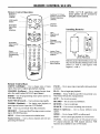
REMOTE CONTROL
Remote
Control
SC2105
Operation
Returns to
Previous
Channel
Switches TV Picture
between TV and VCR
Channel Selectors
(Tuners)
I
_
VCR On/Off
Switch
CHANNEL
NOTE: All VCR operations
and
menu options can be accessed
by
using the remote control.
Channel
Selectors
Accessess
Recording
Start
Locations
Installing Batteries
PLAY
Tape
Play/Record
Options
REWIND_]_,.____.__Fk_TFI_
Chooses
Accessess
Tape Counter
Display
o
-
o
,,
m
Tape Recording
Speed
MEMORY
®®®
Direct
Channel and
Programming
Entry
m
Instant Timer
Recording (ITR)
Selector
®@®
®®®
Push in Tab,
Lift to Remove
QUIT
A
O©O
SELECT
MENU
(o
•
Select/Adjust
Menu Options
-ADJUST
o)
v
II ,,_
Batteries are provided with this remote, but
they must be installed. Match positive with
positive (+ with +), and negative with
negative (- with -).
<
Remote Control Keys
ADJUST (Left/Right)Use to change status of menu
option. Also used to adjust tape playback tracking.
PAUSE --- Use to pause tape temporarily
or record.
CHANNEL (Up/Down)-Use to change favorite channels. Also used to select AUX A/V input channel.
PLAY--
ENTER --Use for programming
VCR status display.
FAST FWD (Forward)
Use to begin tape playback.
POWERTurns VCR On and Off. Concurrently
VCR Timer Off and On, if programmed.
menu options and to see
-- Use to advance tape rapidly.
to
ITR -- Use to access Instant Timer Record feature.
MEMORY -- Use to zero Real-Time
tape to M 0:00:00 position.
tape counter or return
-- Press to see menus and available
RECORD
-- Use to access record feature.
REWIND
-- Use to rewind tape.
SEARCH
-- Use to access recording
SELECT
options.
(Up/Down)-
keys -- Use to choose
information.
channels
start locations.
Use to choose
SPEED -- Use to change EP/SP recording
items.
STOP -- Use to cancel tape playback
Numbered
gramming
turns
QUIT -- Use to exit any menu.
FLSHBK (Flashback)Use during tape playback
pause tape and return to previous VCR channel.
MENU
during playback
and enter pro-
different
menu
speed.
or record modes.
TV/VCR -- Use to switch source of TV picture between
TV channel selection and VCR channel selection. VCR
functions are available for use in VCR mode.
14
VCR MENU OPERATIONS
Available
Menus
AUTO CHANNEL:
CHANNEL
ei
I_.
Mo adjust
To exit press _
: 20 TV
LANGUAGE
SELECT:
Bto
LANGU,_,GESE
Bto _elect
select
[] to adjust
_
T ) exit press rgit_
To
SPEED
ct
|[] :to
oEP
e
just
llto select
adjust
To exit
:it press
pre _ _
[]
_
•
RECORDMODE:
PLAYBACKMODE:
SOURCE SELECT:
ON-SC[ EEN DISPLAY:
DI'
ON-SCREEN
elec
_
t
[] to adjust
To exitt press r_lrrJl
1
AUDIO
NOTE: AUDIO menu is provided
only with stereo VCRs
CLOCK TIMER SETUP AUDIO
[]
to select
to adjust
To exit press
J
MAIN MENU
How to Access Menus
Basic Menu Operation
1. Press MENU to see main menu.
2, Press ADJUST
Left/Right
sub menu to be used.
Use
Remote Control
repeatedly
to select desired
3. Press MENU to see options on selected sub menu.
TVNCR
O
@®@
®®®
@@@
_@_
4.
Use to choose
and modify options
<
ENTER
CD
CD
;ELECT
MENU
repeatedly
to change
status
=
Press QUIT to exit menu, or wait a few minutes and the
VCR returns to normal operation.
Special Menu
L,
llll_l_T_/t;l_'til¢]h'lRffliIL'4[e],'
Bto select
[] to adjust
To exit press r_
%
®)
How to Access Special Menu
_
NOTE: Menu operations are done with the VCR and TV
turned on, and the TV tuned to the VCR video output channel
(3 or 4). Also, the VCR must be in the VCR tuner mode of
operation. Press TV/VCR repeatedly
pears in the VCR front panel.
Press ADJUST Left/Right
of option to desired value.
ADJUST
<
to choose desired option to be
=
©
O0
Up/Down
Auto Daylight Savings Menu
QUIT
A
V
Press SELECT
changed.
Use
select
VCR totuner
until vcR symbol ap-
15
1,
Press MENU to see main menu.
2,
Press 4567 to Access Special Menu.
3,
Press SELECT Up/Down to choose Auto Daylight Savings. Press ADJUST Left/Right to choose ON/OFF.
4,
Press QUIT to exit menu system.
VCR MENU OPERATIONS
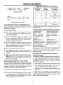
How to Set Clock
Clock
Menu
The Clock Menu is used to set the clock in the VCR to the
current date and time.
1, Choose the CLOCK
Access Menus."
m
DAY
YEAR
TIME
: 26 FRI
: 1996
: 11:06 AM
menu
as described
in "How
to
Press SELECT
Up/Down
arrows
and ADJUST
Left/Right arrows to choose and specify current month,
day, and year.
For example: use SELECT Up/Down arrows to choose
MONTH position, and use ADJUST Left/Right arrows
to choose current month, (JANUARY,
FEBRUARY,
MARCH etc.)
Bto select
[] to adjust
To exit press I_
TYPICAL CLOCK MENU WITH
DATE AND TIME SETTINGS
3.
The clock must be set before you can
record by using the TIMER menu.
Press SELECT Up/Down arrows to choose TIME position. Use numbered keys or press ADJUST Left/Right
to set current time and AM or PM as appropriate.
4. Press QUIT to exit the menu system.
NOTE: This VCR can adjust the clock automatically
for
Daylight Savings Time. See "Auto Daylight Savings Menu"
for details.
You may have to reset the CLOCK if a
power outage lasts for more than 15
minutes.
Timer Menu
The timer menu is used to tell the VCR when to record a
program
fr_l
automatically
MONTH :
JULY
DAY
START
26 FRI
11:16 AM
:
:
STOP :
CHANNEL :
SPEED
:
REPEAT :
Bto select
)NTH :
DAY
:
START :
STOP
:
CHANNEL
SPEED
REPEAT
Bto select
[]
11:46AM
20TV
EP
ONCE
w to adjust
To exit press _
Selected
specily. You can specify eight different
corded in a one-year period.
on the day and at the time you
•
_.
_]
To exit press _
Mode (Timer)
SPEED
:
REPEAT
:
nto select
[] to adjust
._
To exit press _
Program
Number
When highlighted, press ADJUST
to choose next program (Program
Day of Recording
:
:
STOP :
CHANNEL :
mmm
Recording
Month of Recording
to be re-
MONTH :
DAY
START
:
:
:
to adjust
events
<1_
2).
Start Time of Recording
REPEAT OPTIONS
Stop Time of Recording
Channel
ONCE -- Records only one time
WEEKLY -- Records one time each week
of Recording
DAILY --
Speed of Recording
Frequency
To exit press
of Recording
How to Use Timer
1.
Choose TIMER
Menus."
1
3,
Records on time each day,
Monday thru Friday
NOTE:
__E. appears in front panel when the VCR is
placed in the TIMER mode by pressing POWER to turn the
VCR off.
menu as described in "How to Access
Press SELECT Up/Down
program the timer.
and ADJUST
Left/Right
to
_
Press QUIT to exit menu system.
16
it cannot be operated manually. If needed,
While
is operating
TIMER
press VCR
POWER
to release InVCR
frommode,
Timer mode.
VCR MENU OPERATIONS
Setup
Menu
The Setup Menu is used to customize the operation of the
VCR for your particular system and needs. Choose SETUP
Menu as described in "How to Access Menus."
TUNING BAND:
CH. ADD/DEL:
SOURCE SELECT:
ON-SCREEN DISPLAY:
LANGUAGE SELECT:
IRto select
_ to adjust
To exit press
AUTO CHANNEL
Finds all active channels and stores them in the memory
Up/Down. Press ADJUST Left/Right to begin search.
TUNING BAND
Designates the type of equipment (TV or CATV) that is connected to the ANT IN jack on the VCR.
Choose TV if you have an antenna connected to the VCR. Choose CATV if you have a cable system
(with or without a cable box) connected directly to the VCR.
CH. ADD/DEL
Edits the channels found previously when using AUTO CHANNEL. Use numbered buttons
followed by the ENTER key to select the channel to be edited (e.g., to ADD channel 3, press 3 then
the ENTER key). Press ADJUST Left/Right to ADD or DEL (Delete) channels to create your own
list of favorite channels.
SOURCE
Selects the equipment (TUNER or AUX) that is to be used as the source of the program to be
watched or recorded. Choose TUNER if you want to use the channel TUNER in the VCR to select
!the desired program. Choose AUX if you want to see the program from accessory equipment, such
as a camcorder, connected to the Audio/Video (A/V) IN jacks on the VCR.
SELECT
of the VCR for access by Channel
ON-SCREEN DISPLAY
Selects whether or not you see VCR menus and Status Displays on the TV.
LANGUAGE SELECT
Selects the language (English, Espafiol or Fran_ais) used to showVCR menus and Status Displays on
the TV.
Audio Menu
r-
-N
II1_[_,1-'11]hVA[*]
H7
PLAYBACKMODE:
-']1i
:1:1_[*
The Audio Menu is provided only with stereo VCRs. It is
used to specify the type of sound format to be used when
recording or playing a tape. Choose AUDIO Menu as described in "How to Access Menus."
Bto select
[] to adjust
To exit press
RECORD MODE
iSelects the audio format (STEREO, MONO or 2ND AUDIO) to be used when recording a program.
STEREO records sound from the left and right audio channels/tracks in stereophonic format.
MONO (Monaural) records sound in monaural format even if the program is in stereo.
2ND AUDIO records the Second Audio Program (SAP) channel/track, if present, in addition to
the stereo audio channels/tracks. SAP usually contains audio in another language.
PLAYBACK MODE
Selects the audio format (HI-FI or NORMAL) to be used during tape playback.
HI-FI (High Fidelity) provides stereo sound, if present on the tape, to the Left and Right AUDIO
output jacks on the back of the VCR.
NORMAL provides monaural sound regardless of the audio format present on the tape.
17
WATCHING
VCR
Zenith TV
All-Channel
Antenna
Cable TV
Wall Jack
TV THROUGH
_
7
Or
Direct Cable
Zenith Stereo VCR
VHF-UHF
CABLE IN
Typical
Cable Box
From
Cable-TV
System
I.-.
I
I
3 _-----'14
j=,
_
CH3_---'-"IcH4
I'-__,N
I
Or'
I_)VHF/UHF/CATV
I
I%put
OUT_>cable
AUDiOVIDEOIouT
OUT I
VCR Output to TV
(Channel 3 or 4 when
VCR is on and TVNCR
is in VCR position)
VIDEO
IN
AUDIO
IN
IN
Box-to VCR
?
(_i_ (_
'1 I
{
Audio/Video
Output to TV
Block Diagram of Typical Video System
VCR is Turned Off
1.
VCR Is Turned On and You Want to Select
Channels at VCR
Turn TV on.
2. Select channel to be watched at TV. If you have a cable
1.
box, select the cable box output channel (usually 3 or 4)
at the TV. Cable box channels are selected at the cable
box.
2, Place VCR in VCR mode by pressing TV/VCR
on remote control repeatedly
until
appears in the VCR front panel.
VCR Is Turned On and You Want to Select
Channels at TV
3.
4.
Select channel to be watched at VCR. If you have a
cable box, select the cable box output channel (usually
3 or 4) at the VCR. Cable box channels are selected at
the cable box.
Select channel to be watched at TV. If you have a cable
box, select the cable output channel (usually 3 or 4) at
the TV. Cable box channels are selected at the cable
box.
Camcorder
switch
VCR symbol
Select the VCR output channel (3 or 4) at the TV. If you
have connected your VCR to the A/V input jacks on the
TV, you should select the A/V source at the TV for
improved picture performance.
TV/VCR switch on
remote control repeatedly until the VeR symbol disappears from the VCR front panel.
the
3.
1. Tum TV and VCR on.
2. Place VCR in TV mode by pressing
Turn TV and VCR on.
Is Connected to VCR
Back Panel of Stereo VCR
Select AUX Channel
on VCR for Viewing
1. Turn TV and VCR on.
i®o ®loo,®
I
1
Place VCR in VCR mode by pressing TV/VCR switch
on remote control repeatedly
until the VCR symbol
appears in the VCR front panel.
|
Select the VCR output channel (3 or 4) at the TV. If you
have connected your VCR to the A/V input jacks on the
TV, you should select the A/V source at the TV for
improved picture performance.
=
Select
AUX
channel
at VCR
by
using
Channel
Up/Down to select the next channel after the highest or
lowest channel programmed
in the VCR.
A/V cable is not provided with VCR.
,_
TURN OFF POWER OR UNPLUG VCR
BEFORE MAKING ANY CONNECTIONS
18
PLAYING TAPES
VHS Cassette
-'@ 0"-0"-"
Cassette
Controls
LP (Long Play)
1 Hour
1 Hour, 30
Minutes
T-60
1 Hour
2 Hours
3 Hours
IT-120
2 Hours
4 Hours
6 Hours
T-160
2 Hours,
40 Minutes
5 Hours,
20 Minutes
8 Hours
on VCR
_
STOP
TV/VCR
O
Controls
Automatic
1.
2.
on Remote
Times
SP (Standard
Play)
30 Minutes
PLAY
POWER
PlaybackJRecord
Length
T-30
AEJECT
EP (Extended
Play)
Control
Playback (No Safety Tab)
Tape playback begins automatically, if the safety tab is
removed from the cassette case. Simply insert the prerecorded VHS cassette into the VCR. Power turns on and
NOTE: Your VCR sets the playback speed automatically to
the speed used to record the tape. This VCR records only in
SP and EP speeds.
Manual Playback (Has Safety Tab)
playback begins automatically.
1.
Press POWER to turn VCR on.
Select the VCR output channel (CH3/CH4) at the TV.
Or, select the AUX (Auxiliary)
source at TV to see
picture if you are using the A/V jacks.
2.
Insert a prerecorded
3.
Press PLAY to begin playback.
VHS cassette
into the VCR.
4. Select the VCR output channel (CH3/CH4)
at the TV.
Or select AUX (auxiliary) source at TV to see picture
if you are using the A/V jacks.
Unloading
Cassette
Safety Tab
Shown in
Place
Auto/Manual
the Cassette from the VCR
1.
Press STOP if the tape is playing.
2.
Press and hold STOP/EJECT
at the VCR
until the
cassette is ejected from the VCR.
Index Search
Tracking Adjustment
Your VCR adjusts tracking automatically when you play a
tape. If the tape was recorded on a different VCR, streaks
(video noise) may appear. While the tape is playing, press
ADJUST (Left/Right) to adjust the tracking manually.
An index code is inserted oll the tape at the start of each
recording. You can use the index codes to search and rapidly
locate the segment of the tape you want to see. Index search
can only be used on tapes recorded on this VCR.
Real-Time
Rewind the tape to the beginning and press SEARCH. Input
the number of index codes from the beginning of the tape
that will get you to your playback start location, and then
press FAST FWD. The VCR advances the tape to that
location and begins playback. Or, during playback, press
STOP and then press SEARCH.
Input the number of
index codes that need to be passed to reach your desired
playback start location, and press FAST FWD or REWIND,
as appropriate.
Tape Counter
Press ENTER two
display on the TV
move all displays.
insert a cassette or
times to keep the real-time tape counter
screen. Press ENTER repeatedly to reThe counter resets to 0:00:00 when you
when a tape is rewound to its beginning.
Pause/Forward/Reverse
Slow-Motion
Video
(While in Play mode) Press PAUSE, for still video. Press
PAUSE again, and follow on-screen instructions for Forward or Reverse slow motion. Selected direction is used
until you press PLAY to resume normal tape playing.
MUST PASS FOUR INDEX
CODES TO SEE PROGRAM #4
Tape Rewind and Fast Forward
I
(While in Stop mode) Press and release REWIND or FAST
FWD, as desired. Press STOP when tape reaches desired
location.
OF TAPE
[I
INDEX
CODE
#1
Reverse/Forward
Search
and Jet Search
(While in Play mode) Press and release REWIND or FAST
FWD, as desired. Press and hold REWIND or FAST FWD
for Jet Search. Press PLAY to resume normal tape playing.
19
"l
#I
I
INDEX
CODE
#2
#2
I
INDEX
CODE
#3
#3
I] #_
INDEX
CODE
#4
OF TAPE
INSTANT RECORDING
Preset Time Periods
O
POWER@
SP/EP
_a
REC/ITR
_
___)A
•
Presses of ITR
REC/ITR
STOP/
EJECT
1 (Press/Hold)
Controls on VCR
POWER
O
SPEED
0
STOP
TV/VCR
What You Are Watching On TV
Instant Recording is a method of attended recording where
you record until the end-of-tape
is reached or you press
STOP to stop recording.
1.
4.
Select the VCR output channel (3 or 4) at the TV. If
you have connected your VCR to the A/V input jacks
on the TV, you should select the A/V source at the TV
for improved picture performance.
the channel
to be watched
and recorded
at the
VCR. If you have a cable box, select the cable box
output channel (usually 3 or 4) at the VCR. Cable box
channels are selected at the cable box.
5, Insert a VHS cassette
6. Press
SPEED
speed is always
recording
speed,
SP, unless
if
30 minutes
3
1:00
1 hour
4
1:30
1 hour and 30 minutes
5
2:00
2 hours
9
4:00
4 hours
10
0:00
VCR turns off
Instant Recording
(until end-of-tape)
Instant Timer Recording
(Preset Recording Times)
PAUSE -- Momentarily
pauses recording. Press
PAUSE again to resume
recording.
STOP or STOP/EJECT -Stops and exits recording
mode.
REWIND or REW --
REWIND or REW --
Rewinds tape until STOP or
STOP/EJECT is pressed or
tape is rewound fully,
Rewinds tape until STOP or
STOP/EJECT is pressed or
tape is rewound fully.
contin-
2,
Press ITR or REC/ITR repeatedly
to select a preset
recording time period. Each subsequent press of ITR or
REC/ITR increases the recording time by 30 minutes
until a maximum of 4 hours is reached.
controls
have
a RECORD
button
to active
The program you record is selected using the channel selector in the VCR and the program you watch is selected using
the channel selector in the TV. If you have a cable box
connected to your VCR, you cannot record one program and
watch another program.
By Using Preset Time Periods
Perform
Some remote
Recording One Program While Watching
Another Program
is reached, or until you press
1.
time counts down until the record-
which may be used instead of ITR or REC/ITR
Instant Recording.
EP is
Instant Timer Recording
(ITR) is a method of attended
recording where you record for a specific preset time period,
instead of recording until the end-of-tape
is reached. For
example, you may want to record a program for only 30
minutes because that is when the program ends.
steps I through
0:30
NOTE:
R_ECappears in the VCR front panel. Recording
Recording
2
Stops and exits recording mode.
7. Press and hold ITR or REC/ITR until recording begins.
ues until the end-of-tape
STOP to stop recording.
Until end-of-tape
STOP or STOP/EJECT --
tape into the VCR.
or SP/EP to select
desired. Recording
selected.
Time
Options Which Can Be Used While Recording
Turn TV and VCR on.
Select
Current
NOTE: Preset recording
ing time is over.
2, Place VCR in VCR mode by pressing TV/VCR on
remote control repeatedly until the VeR symbol appears
in the VCR front panel.
3.
Preset Time For
Recording
Display
Provided
RECORD
Controls on Remote Control
Recording
or =
For ITR Recording
1. Perform steps 1 through 7 above for Instant Recording.
9.
Place VCR in TV mode by pressing TV/VCR on remote
to turn off yea symbol in the VCR front panel.
3. Select program to be watched using the channel selector
in the TV.
7 above for Instant Recording.
NOTE: To return to the program you are recording, select
the VCR video channel (3 or 4) at the TV and place the VCR
in the VCR mode by pressing TV/VCR on remote to show
VCR symbol in VCR front panel.
20
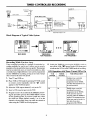
TIMER-CONTROLLED
Zenith
All-Channel
Antenna
Cable TV
Wall Jack
Direct Cable
_-- )...
Or
S,stem
Zenith Stereo VCR
I
OOT H- "
c.3 0.,
VCR Output to TV
(Channel 3 or 4 when
VCR is on and TVNCR
is in VCR position)
AUDIO VIDEO I
VIDEO
IN
"F'°"F'cATv
OOT
OOT
I
I
1%; x I
CableBox
to VCR
VHF-UHF
CABLE IN
CHANNELI
c.o, oox
Ol T
Io, IVv
co0,e-Tv
TV
7
Typical
From
RECORDING
IN
t(_(_
'1 I
ID,
_,
AUDIO
IN
Audio/Video
Output to TV
Block Diagram of Typical Video System
I'-,I:Ielef: r_,l LfJm,
_1
CLOCK TIMER SETUP AUDIO[
[]
MONTH
:
DAY
:
START
:
STOP
•
CHANNEL'
SPEED
REPEAT
to select
to adjust
To exit press r_
•
MAIN MENU
:
:
:
II
Ilto select
IB to adjust
To exit press _
II
II
SPEED
•
%.
4.
Insert a VHS cassette
5.
Program events to be recorded in the TIMER by following the procedure given in the TIMER MENU section
of this operating guide. If you have a cable box, select
the cable box output channel (usually 3 or 4) as the
channel to be recorded. Keep your cable box turned on
when using the TIMER to record programs.
8
turn off the VCR. n_g appears in the VCR front panel
to indicate the VCR is in the TIMER mode of recording.
VCR Operation
VCR
POWER
(3 or 4) at the TV.
tape into the VCR.
21
with Timer
TIMER
STATUS
Turned
Off or On
VCR OPERATION
On
Off
Disables timer-controlled
recording if an event is
programmed in the TIMER.
All other VCR operations can
be used as desired.
Off
On
Enables timer-controlled
recording if an event is
programmed in the TIMER.
VCR cannot be operated
manually while the TIMER is
enabled. The assumption here
is that you want to record at a
later time if you have
programmed the TIMER.
VCB symbol
Select the VCR output channel
To exit press 1'_
TIMER MENU
FOR PROGRAM
2. Place VCR in VCR mode by pressing TV/VCR switch
3.
:
REPEAT :
Bto select
[] to adjust
6. Enable the TIMER by pressing the POWER switch to
Turn TV and VCR on.
on remote control repeatedly
until the
appears in the VCR front panel.
:
:
START :
STOP
:
CHANNEL :
TIMER MENU
FOR PROGRAM 1
Recording
While You Are Away
Timer-controlled
recording is a method of unattended recording available for you to use. It allows you to record a
program on the day and at the time you specify. The program
may be recorded only once, or it can be recorded on a daily
or weekly basis. Eight different events can be programmed
into the TIMER for recording, as long as no event overlaps
other events in the same time period.
1.
MONTH
DAY
SERVICE INFORMATION
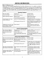
Before Calling for Service
Please refer to the following Problem/Resolution
Chart before calling for service. As a prelude to solving any
VCR problem, turn on TV and VCR. Select appropriate input for the TV to receive the video signal from the
VCR. Most likely you will use the Antenna In connection to the TV, and select channel 3 or 4 at the TV. Place
the VCR in the VCR mode by pressing TV/VCR on the remote repeatedly until vcs symbol appears in the VCR
front panel. If you have a cable box, turn on the cable box and select the cable box output channel (usually 3 or 4) at
the VCR.
Operating
Observed
Condition
Problems
Possible Cause
Probable Solution
No power to the VCR.
Power cord is not connected.
Connect power cord.
Remote control does not function.
Batteries are weak.
Replace with new batteries.
You are too far away from the VCR.
Move closer to the VCR.
Source for TV is not selected properly.
Set INPUT source on TV to Audio/Video In,
or tune TV to Channel 3 or 4, as appropriate.
TV/VCR mode for VCR is set to TV.
Press TV/VCR on remote repeatedly to choose
VCR mode. yen symbol appears in VCR
front panel.
VCR is locked up.
Disconnect VCR power cord for five (5)
minutes. Reset clock and other features as
No picture appears on TV screen
from any VCR function.
VCR features do not function. VCR
does not respond to remote control
functions or buttons on VCR.
necessary.
Channel
Tuning Problems
Some channels are skipped over
when using Channel Up/Down.
Those channels were deleted with the CH.
ADD/DEL option.
Use CH. ADD/DEL to restore channels. See
SETUP menu for details.
Picture and sound are weak or
Antenna or cables are loose.
Tighten connections or replace cable.
Wrong TUNING BAND option is being
used.
Try all TUNING BAND options. See SETUP
menu for details.
missing.
Playing Tapes (Playback)
Problems
Tape will not rewind or fast forward.
Tape is fully rewound or is at its end.
No action available.
Mechanical sound is audible during
playback.
Note: This is normal operating sound from
internal mechanisms.
No action available.
Tape playback does not appear on
TV screen.
Source for TV is not selected properly.
Set Input source on TV to Audio/video In, or
tune TV to Channel 3 or 4, as appropriate.
TV/VCR mode for VCR set to TV.
Press TV/VCR repeatedly to choose VCR
mode. yen symbol appears in VCR front
ipanel.
Tape is a rental or was recorded on another
VCR.
Use ADJUST (Left or Right) for manual
tracking adjustment while tape is playing.
Tape heads are dirty.
Clean Video heads.
Tape tracking needs to be adjusted while in
slow-motion playback.
From STILL video mode, enable slow-motion
playback. Use ADJUST (Left or Right) to
adjust tracking for best picture. Return to
PLAY mode, then press PAUSE for STILL
video.
Video "Noise" (horizontal streaks)
appear during normal tape playing.
VCR Status Display "flickers" when
using STILL video during tape
playback.
22
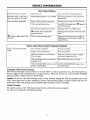
SERVICE INFORMATION
Recording Problems
Camcorder image is not shown.
Camcorder is off.
Turn camcorder on and operate properly.
Camcorder image via A/V input to
VCR is not shown on TV screen.
VCR SOURCE SELECT is set to TUNER
Use Channel Up/Down to select AUX A/V
input channel.
Timer recording is not possible.
Clock in VCR is not set to correct time.
Set clock to correct time. See CLOCK menu.
VCR is on which disables timer.
Turn VCR off to enable timer, n_R appears in
the VCR front panel.
Timer has been programmed incorrectly.
Reprogram Timer. See TIMER menu.
_.En..indicator does not appear after
programming timer.
Reprogram Timer and turn VCR off to enable
timer.
VCR is in Timer Recording mode.
This is normal indication that the VCR is in
_,._ indicator appears after VCR is
turned off.
-
TIMER mode. If needed, disable TIMER by
turning VCR on.
Stereo Audio Record and/or Playback Problems
Stereo is not present from VCR
output.
TV is not Stereo compatible.
No action is possible.
Program is not in stereo format.
No action is possible.
VCR A/V Out jacks are not connected to
TV A/V In jacks.
Make AN connections. Stereo is available
VCR Audio/Video Out is not selected for
viewing at the TV.
Select AUX or A/V source as TV input.
VCR AUDIO RECORD mode is set to 2nd
AUDIO or MONAURAL.
Set VCR AUDIO RECORD mode to Stereo.
See AUDIO menu.
only via A/V output from VCR.
Automatic
Video Head Cleaning
The VCR automatically cleans the heads as it is used. However, after long periods of use, the video heads may
become clogged with accumulated dirt, causing distortion. When this occurs, use a do-it-yourself
wet-head
cleaning cassette available from your Zenith dealer.
Caution: Do not use a dry-head cleaning system. It may seriously damage the VCR and cassettes used in the
VCR. Visual signs such as snow, streaking in picture, and horizontal pulling of picture indicate the need for
professional video head cleaning. See your Zenith approved service center for cleaning.
Cabinet
Cleaning
The outside surfaces of the VCR may be cleaned with a soft lint-free cloth as required.
Use care not to scratch the VCR during cleaning.
23
Recommended
Accessories
For Your VCR
Videotape
Rewinder
Wireless
Headphones
Video Transfer
System
Broken
or Lost
Remote
Control?
For an exact
replacement
remote control for your
new Zenith VCR, see your
local Zenith dealer or order
direct by calling
1-800-255-6790.
To
assure the correct remote
for your new Zenith, please
have your VCR's model
number ready when you call!
Eliminate
wear and tear
on your equipment
Prolong the life of your
expensive VCR or
camcorder with this one
way videotape rewinder:
• Load up a second video
while the first rewinds.
• Help.s eliminate costly
repair work.
• Works with full size
camcorders too!
• Easy to use.
ALG1 t 40
One Way Video Rewinder
Complete
Cordless
Stereo Headphones
Relax and enjoy your favorite
music or "IV programs
without disturbing others:
• Operates with any TV,
VCR or Stereo System.
• Works up to 50 feet.
• Separate left and right
volume controls.
• Great for the hard of
hearing.
ALG2032
Wireless Headphone System
Don't let your
memories
fade away!
Preserve the joy of
weddings, graduations and
birthdays for years to come:
• Copies photos, slides and
home movies onto any videotape easily.
• Works with all film
projectors and
camcorders.
• Built-in lens prefocuses
for sharper results.
ALG 1344
Video Transfer System
Only $39.95
Only $12.95
Only $69.95
Only $49.95
Photocopy
Toorderthesefineaccessories,
pleasecompletethis orderform
andreturna photocopywith
yourpaymentto:
Page and Detach Here
iQuantity
Description
Item Number
Price per Item
Total
Price
Accessory Offers
Zenith Video Tech Corporation
1000 Milwaukee Avenue
Glenview, Illinois 60025-2493
Sales Tax:
CA 7.75%,
NJ 6%,
E3
rq
Check or Money Order
(Made Payable to Zenit!
GA 6%,
PA 6%,
SubTotal
Please add your state sales tax if you
live in one of the following states.
Or Call 1-800-255-6790
IL 8.75%,
RI 7%,
KS 4.9%,
TX 7.75%,
KY 6%,
VA 4.5%,
ME 6%
State Sales Tax
WA 8.2%
Shipping and Handling
deo Tech Corp.)
(Note: Orders can only be sent to
customers within the United States.)
Total Arr_unt of Order
Ship To:
Account #
IIIIIIIIIII
IIII
I.a
Address
Expiration Date
IMPORTANT:
Signature
PLEASE
BE SURE TO COMPLETE
THE INFORMATION
BELOW
/
I"V Model
(Irom
Number
Sticker
on back
TV Serial
of unit)
Number
(from Stoker
on back of unit)
Month
(Approx.
/
Day
Zip/Postal
State
Year
date of purchase)
PLEASE ALLOW 2-3 WEEKS FOR DELIVERY
VCRACCS3
c_y
Apt#
Telephone_(
)_
Code
$4.50
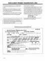
REPLACEMENT
PRODUCT
REGISTRATION
CARD
You could win a full refund on your new Zenith product.
Product Card lost or misplaced?
Look for the Product Registration Card on your new video
product.
The Product Registration Card furnished with your video product is pre-printed with its Model and Serial numbers. Please
fill out the card and mail it at your earliest convenience. It is
imperative that Zenith know how to reach you promptly if we
discover a safety problem that would affect you. If the original
card has been lost or misplaced, you may use the replacement
card provided below. Either card will qualify you for the free
drawing, but you are limited to only one entry in the drawing.
Complete the card, place it in an envelope and mail it to:
Each month a drawing is held by Zenith from the completed
Product Registration Cards received during the preceding
month. Zenith will reimburse the winner for the full purchase
price of the product purchased.
In order to participate, simply complete and return the Product
Registration Card at once, even if you choose not to complete
the information and interests portion of the questionnaire.
Zenith Electronics Corporation
P. O. Box 173262
Denver, CO 80217-3262
Use the replacement Product Registration Card only if the
original card has been misplaced or lost.
The odds of winning the free drawing described above, depend on the number of participants. Free drawing offer is
void in Canada and other places where restricted or prohibited by law. Offer is void for Hotel/Motel and Institutional
models. Rental models 'are not eligible.
PHOTOCOPY AND CUT ALONG DASHED LINE
H5Y01-01
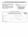
Zenith
@
Product
Registration
Card
Please Print Clearly or Type
1.[--[Mr.
2. J--]Mrs.
@Area
3. r-'lMs.
First Name
4. l--lMiss
Initial
Street
Code Telephone
IIIIIII
I
I-IIII
Last Name
:_,_,_,_,_,_%_,_,_,_
:_iii!iiii
Apt,:_N_;
City
jii!iiiiiiiiiiiiii!i?
_i_i_i_i_i_i_i_i_i_i_
:_i_i_i_i_i_i_i_i_i_i_!_i_i_
State
Mo.
Day
Yr.
I I II I I!_1
_,,,...........
,..........,......,,,.......,
_
¸__:5!11111!
CopyNumbersHere
From Label on Set
VCRREGI
Please record the model number
and serial number from the sticker
on the back of your set.
A VISO PARA NUESTROS
CLIENTES
Zenith publica muchos de sus manuales de instrucciones en
idioma espafiol. Si le interesa pedir la versi6n en espafiol de este
manual, llene el formulario provisto a continuaci6n, fotoc6pielo y
envieio a la direcci6n indicada.
DE HABLA
HISPANA
Instrucciones:
1. Llene el formulario proporcionado a continuaci6n con la
informaci6n solicitada.
2. Haga una fotocopia del formulario de pedido y enviela a:
No todos los manuales de instrucciones est_indisponibles en
espafiol. Sin embargo, podemos proporcionarle el manual que
corresponde a un modelo similar a este, en el cual se describen
casi todas las caracteffsticas del producto que usted utiliza.
Service Literature Department
Zenith Video Tech Corporation
1000 Milwaukee Avenue
Glenview, IL 60025-2493
El manual en espafiol es gratis.
Fotocopie ia p gina y corte |a linea punteado
f
Formulario
de pedido de su manual de instrucciones
(Este formulario de pedido es solo v_ilidopara el producto descrito en este manual)
Nfimero de modelo
(1o encontrar_i en la parte posterior del aparato)
Nombre
Direcci6n
Ciudad
Pals (si afuera de E.E.U.U.)
VCRCOUPI
Apartamento
Estado
C6digo postal
#
2015-3120 _
k,, y, I-TOOLJ
YOUR ZENITH VCR WARRANTY
VIDEO
CASSEITE
RECORDER
OR PLAYER
Owner's
Welcome into the Zenith family? We believe that you
will be pleased with your new Zenith video product.
Please read this Warranty carefully. It is a "LIMITED
WARRANTY" as defined under Federal Law. This
warranty gives you specific legal rights, and you may
also have other rights that vary from state to state
within the U.S.A.
Responsibility
Effective Warranty Date -- Warranty begins on tile
date of original consumer installation. For your convenience, keep the dealer's dated bill of sale or delivery
ticket as evidence of the purchase date.
Operating Guide -- Read your operating guide carefully so that you will understand the operation of your
video product and how to adjust the customer controls.
Carry-In Service -- The video product must be taken
to a U.S. or Canadian Zenith authorized service center
Zenith "sResponsibility
Service Labor -- During a period of 90 days from el:
fective warranty date, Zenith will pay for service labor
by a U.S. or Canadian Zenith authorized service center
when needed as a result of manufacturing defects.
Paris -- New or remanufactured replacements for factorydefective parts will be supplied by a U.S. or Canadian
Zenith authorized service center for one year from effective warranty date. Such replacement parts are warranted
for the remaining portion of the original warranty period.
Not Covered -- This warranty covers manufacturing
defects and does not cover installation, adjustment of
customer controls in the home, installation or repair of
home antenna systems, cable converters or cable company-supplied equipment; it also does not cover
damage due to misuse, abuse, negligence, acts of God
or other causes beyond the control of Zenith. Any alteration of the product after manufacture voids this
warranty in its entirety.
ZENITH
TV Set Performance -- It is the owner's responsibility
to maintain the TV receiver with which the video product is used, and the associated antenna system, in
proper operating condition.
Important: Product Registration -- Please fill out
and mail your Product Registration Card. It is imperative that Zenith know how to reach you promptly if we
should discover a safety problem that could affect you.
Warranty Service -- For warranty service information, contact your Zenith dealer preferably, or any U.S.
or Canadian Zenith authorized service center. Parts and
service labor that are Zenith's responsibility (see
above) will be provided without charge. Other service
is at the owner's expense. If you have any problem in
obtaining satisfactory warranty service, write:
Zenith Electronics Corporation
Customer Service Department
1000 Milwaukee Avenue
Glenview, Illinois 60025-2493
Telephone: (847) 391-8752
Mon-Fri, 8:00 a.m. - 4:30 p.m. Central Time
NOTE: Before you ask for Warranty service, check the
Operating Guide section entitled, "SERVICE INFORMATION." It may be possible to avoid a service call.
ADDITIONAL
for warranty service and must be picked up by the
owner.
PROTECTION
PLAN AVAILABLE
Zenith offers you the opportunity to obtain additional long-term protection against failure of your new VCR. Our VCR Protection Plan enables you to avoid any unexpected
repair expenses and keep your VCR in top condition. It guarantees you genuine Zenith
replacement parts and service from a Zenith authorized service center.
Be sure to send in the Product Registration Card. We will send you an application for
the Protection Plan near the expiration of the manufacturer's warranty. For additional
information, call (847) 391-8757.
ZENITH ELECTRONICS CORPORATION
1000 MILWAUKEE AVENUE
GLENVIEW, ILLINOIS 60025-2493
VCRWRR7
Zenith Part No. 206-3102
Printed in Korea
Issue B