1
Advanced
Video
OPERATING
Imaging
GUIDE AND WARRANTY
MTS Stereo Color TV
with
Surround Sound
recycled
paper
Closed Captions
Remote Control
Return the Product Registration
Card, and your TV could be free!
WARNING:
TO REDUCE THE RISK OF ELECTRIC SHOCK DO NOT
REMOVE COVER (OR BACK). NO USER SERVICEABLE
PARTS
INSIDE.
REFER
TO QUALIFIED
SERVICE
PERSONNEL.
TO PREVENT FIRE OR SHOCK HAZARDS, DO NOT
EXPOSE THIS PRODUCT TO RAIN OR MOISTURE.
A
The lightning flash with arrowhead symbol, within an equilateral
triangle, is intended to alert the user to the presence of uninsnlated
"dangerous voltage" within the product's enclosure that may be of
sufficient magnitude to constitute a risk of electric shock to
persons.
The exclamation point within an equilateral triangle is intended to
alert the user to the presence of important operating and
maintenance
(servicing)
instructions
in
the
literature
accompanying the appliance.
Safety Tips
Refer to the "Safety Tips" booklet that came with your
product for important safety considerations.
Note to Cable TV System
Installer
This reminder is provided to call the cable TV system
installer's attention to Article 820-40 of the NEC that
provides guidelines for proper grounding and, in
particular, specifies that the cable ground shall be
connected to the grounding system of the building, as
close to the point of the cable entry as practical.
Power-Cord
CAUTION
Polarization
This product is equipped with a polarized alternatingcurrent line plug (a plug having one blade wider than the
other.) This plug will fit into the power outlet only one
way. This is a safety feature. If you are unable to insert
the plug fully into the outlet, try reversing the plug. If the
plug should still fail to fit, contact your electrician to
replaqe your obsolete outlet. Do not defeat the safety
purpose of the polarized plug.
To prevent electric shock, match wide blade of plug to
wide slot, fully insert.
ATTENTION
Pour _viter les chocs 61ectriques, introduire la lame ia
plus large de la fiche dam la borne correspondante de la
prise et pousser jusqu'au fond.
Copyright © Zenith Electronics Corporation
1993
rvw_l
CONTENTS
INTRODUCTION
Welcome ...........................................
Installation Considerations ...........................
CONNECTIONS FOR YOUR TV
Connection Center On Back Of TV ..................
ii
ii
1-1
Input Sources For Your TV .........................
1-2
Step 1. Make Basic Connections To TV ..............
1-2
Step 2. Make VCR Connections To TV ...............
1-4
Step 3. Make Super-VHS Connections To TV .........
1-5
Step 4. Make Stereo Audio Connections To TV .......
1-6
Step 5. TV Connections to External Speakers .........
1-7
Step 6. TV Connections to Surround Sound Speakers ... 1-7
Step 7. A/V Connections To Front A/V Jacks .........
1-8
THE FIRST TIME YOU OPERATE YOUR "IV
Step
Step
Step
Step
Step
1. Connect The Power .........................
2. Turn On TV ...............................
3. Select Your Viewing Source ..................
4. Use Auto Ch. Search .......................
5. Use Other Options .........................
2-1
2-1
2-1
2-1
2-2
OPERATING YOUR TV
Basic TV Operations
..............................
Sleep Timer ......................................
3-1
3-1
GETI'ING TO KNOW YOUR TV
Front Panel Controls ..............................
4-1
GETTING TO KNOW YOUR REMOTE CONTROL
Operation ........................................
Choose The Operating Mode .......................
TV Operations ....................................
VCR Operations ..................................
Cable-TV Operations ..............................
Preparation For Use ......
.........................
Installing Batteries ................................
5-1
5-1
5-2
5-3
5-4
5-5
5-5
SETUP MENU
Auto Ch. Search ...................................
CH. Add/Del .....................................
CH. Labels .......................................
Tuning Band ......................................
Auto Fine Tune ...................................
Clock Set .........................................
8-1
8-2
8-2
8-3
8-3
8-4
Captions .........................................
CH. Background ..................................
Setup Menu With Auxiliary
Video Source Selected .............................
AUDIO
8-4
8-5
8-6
MENU
General Information
...............................
Bass .............................................
Treble
...........................................
Balance
..........................................
Audio ............................................
SEQ .............................................
Surround
.........................................
9-1
9-1
9-1
9-1
9-2
9-2
9-2
Audio
9-3
Selection
Considerations
......................
VIDEO MENU
General Information ..............................
Contrast .........................................
Brightness .......................................
Color ...........................................
Tint .............................................
Sharpness
.......................................
Color Temp ......................................
Video Filter ......................................
Auto Flesh .......................................
Picture Pref ......................................
10-1
10-1
10-1
10-1
10-1
10-1
10-1
10-1
10-1
10-1
PROGRAMMING
THE REMOTE
Introduction
.....................................
11-1
TV, VCR And
Cable-TV
Operating
CONTROL
Codes
...........
11-2
ON-SCREEN MENUS
Available Menus ..................................
6-1
MAINTENANCE
Summary Of Menu Items ...........................
Basic Menu Operation .............................
6-1
6-2
Caring For Your TV ..............................
Extended Absence
................................
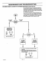
TV Picture Interference
...........................
12-1
12-1
12-1
Before Calling For Service
.........................
VCR Operational
Mode Charts .....................
12-2
12-3
SOURCE MENU
To Select A Source ................................
7-1
AND TROUBLES
HOOTING
Product Registration Card
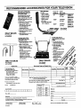
Recommended Accessories For Your Television
Your Zenith Warranty
INTRODUCTION
WELCOME
Welcome into the family of Zenith Color Television owners.
This guide provides instructions on how to operate your
Send the model number, serial number, and date of purchase or original installation, with a full explanation of the
problem and the service history. We will welcome the opportunity'to look into your specific question or problem and
to be of assistance in resolving it promptly.
new TV. It is supplemented by a booklet containing Safety
Tips. We urge you to read these publications carefully so
that you will receive full enjoymentfrom your new Zenith
TV for many years to come.
The model and serial numbers of your new TV are located on
the back of the TV cabinet. For your future convenience and
protection, we suggest that you record these numbers here:
Your new Zenith TV has been designed and built to give
you the very best in quality, features and performance.
There are many regional Zenith distributors and thousands
of distributor-approved
Zenith service centers throughout
the U.S. and Canada who can attend promptly and effectively to ordinaryservice needs.
Model No.
Serial No.
If you should have an unusual performance or service problem
that cannot be satisfactorilyresolved byyour distributorapproved Zenith service center, contact the regional Zenith
distributor in your area, or write:
Zenith Electronics Corporation
Customer Service Department
1900 N. Austin Avenue
Chicago, Illinois 60639-5079
Telephone: (312) 745-5152
Mon-Fri, 8:00 a.m. - 4:30 p.m. Central Time
INSTALLATION
CONSIDERATIONS
,Please read and observe each safety point in the "Safety
Tips" folder when installing and using your TV.
Before you install your "IV...
Ventilation - Proper ventilation keeps your TV
running cool. Air circulates through perforations in the back and bottom of the cabinet. Do
FIXED PATTERN DISPLAY CAUTION - If you use your
TV for video games, teletext or other fixed displays, avoid
setting the BRIGHTNESS control for an excessively bright
picture. A bright, fixed pattern, if used for long periods of
time, can result in a permanent imprint on the "IV picture
tube. You can reduce this possibility by alternating the use
of the fixed pattern display with normal 'IV picture viewing,
by turning down the CONTRAST control for sustained
fixed pattern use, and by turning off the fixed pattern display when not in use.
not block these vents or you will shorten the life
of your TV.
A
A
Power Source - Your TV is designed to operate
on normal household current, 120 volt 60 Hertz
AC. Do not attempt to operate it on DC current.
Power Cord - Your power cord has a
polarized plug as required by Underwriters'
Laboratories. It has one regular blade and one
wide blade and fits only one way into a standard
electrical outlet, ff the blades will not enter
PLUGGING IN YOUR TV - Be sure to plug your "IV into
an "tmswitched" AC power source. The "switched" AC outlets found on some video equipment will not continue supplying power to the TV once the equipment is turned off. If
the power to the TV is interrupted, you will have to reset
the clock in the TV to the current time.
either way, your outlet is very old and nonstandard. A new outlet should be installed by a
qualified electrician.
Safe Operation -- Your "IV is manufactured
and tested with your safety in mind. However,
unusual stress caused by dropping or mishandling, exposure to flood, fire, rain or moisture,
or accidental spilling of liquids into the TV, can
result in potential electrical shock or fire
hazards. If this happens, have your TV checked
by a service technician before using it again.
ii
cswm_t
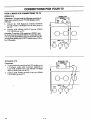
CONNECTIONS
CONNECTION
CENTER
FOR YOUR TV
ON BACK OF TV
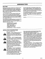
Using these five connections, you can choose from a variety
of antenna sources and audio/video components for your
viewing pleasure. Note that the correct source must be
selected from the SOURCE MENU (as described later in
this booklet) to watch TV. Refer to the illustration while
reading the following descriptions.
The connection center on the back of your TV will be
similar to the one shown below. These connections allow
three basic "types" of video inputs to provide for up to 5 different viewing sources to your TV.
O0
RIGHT
0
LEFT
TO EXTERNAL
SURROUND
SPEAKER
AMP
SPEAKERS
LOOP OUT
I-1
TO OECOOER
VIDEO
WOEO
000
1 IN
rA_'--]
VIDEO 2 IN
vtoeo
000
I I t11
I-- AUOIO
--I
'
E
F
I-I ."
I-1 i
G
@
1.
2.
ANT/CABLE 1 or ANT/CABLE 2
Use one of these jacks for 75-ohm, antenna-type
signal connections to your TV. Attach your antenna, cable-TV
line, or other video component
to
either of these jacks. The input may come from an
outdoor or master antenna, cable-TV decoder box,
or the 75-ohm TV output from a VCR.
LOOP OUT
3.
Use this output jack to route the cable-TV signal
back to the decoder supplied by your cable-TV
system. When connected as shown in Steps 1C and
1D, you can view basic (unscrambled)
cable channels by selecting
the ANT/CABLE
2 source or
premium (scrambled)
cable channels tuned by the
decoder by selecting ANT/CABLE
1 source.
VIDEO 1 IN or VIDEO 2 IN
4.
Video and audio (Base Band) input from VCR or
other video component
(Disc Player). Gives improved picture quality performance
over that obtained through the ANT/CABLE jacks.
VIDEO 1 LOOP OUT
S-VIDEO 1 IN
6.
7.
Input from a Super-VHS VCR. Both left and right
audio jacks are provided
as well as the S-Video
(Y-C) jack.
EXTERNAL SPEAKERS
Terminals
for connecting
external
left and right
stereo speakers.
EXTERNAL AMP
8.
Standard
Phono Jack connectors
external amplifier.
SURROUND
SPEAKER
9.
Use these jacks to send the incoming video and
audio signals (from VIDEO 1 IN) to another component such as a second VCR or TV monitor.
,-_A
5.
1- I
for output
to an
Standard
Phono Jack connector
for output to optional surround sound speakers.
SPEAKERS INT/EXT
Use this switch to turn the TV's internal speakers
OFF or ON when an external audio amplifier or
external speakers are connected
to the TV. (See
steps 4 and 5.)
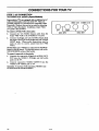
CONNECTIONS
INPUT SOURCES
FOR YOUR TV
FOR YOUR TV
Another common "signal source" is the audio and video
(A/V) from a VCR or video disc player. This type of signal
is called base band (basic video and audio), and is connected to one of the VIDEO IN connections.
Your TV has five input connection areas: ANT/CABLE
1,
ANT/CABLE 2, VIDEO 1 IN, VIDEO 2 IN, and SVIDEO 1 IN. (In addition, some models have a sixth input
area on the front of the TV.) These five inputs allow you to
connect five different "signal sources" to your TV at the
same time. The "Signal Source" refers to the item supplying the picture and sound to your TV.
The most common "signal source" is your outdoor antenna
(or master antenna) or a cable-TV system. This type of signal is called a radio frequency (RF) source, and is connetted to the one of the ANT/CABLE jacks.
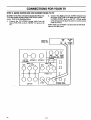
STEP 1. MAKE BASIC CONNECTIONS
A third "signal source" is the input from a Super-VHS
VCR. If you have a S-VHS VCR, use the S-VIDEO 1 IN
video and audio jacks to connect it to the TV.
To use any of these video/audio input sources, you must access the SOURCE Menu and select the "source" which corresponds to the input jacks being used. Refer to the
"SOURCE MENU" in this operating guide.
TO TV
There are four basic hook ups to your TV; outdoor antenna
(or master antenna) with or without VCR, and cable-TV
system with or without VCR. Select the hook up that best
fits your needs. See the following diagrams.
Your connection is made to one of the ANT/CABLE
jacks
on the back of the TV. These jacks accept 75-ohm cable terminated in an F-type male connector. You may want to do
the hook-up yourself, or call a TV service technician, or a
cable company.
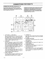
A. Antenna Connection
to TV
If You Have a Round Antenna Wire:
Connect the 75-ohm round antenna wire to either
the ANT/CABLE
1 or ANT/CABLE
2 jack on the
TV.
If You Have a Flat, Twin-Lead
--//I//
/////
Antenna
1.
2.
Connection
ohm
Adapter
Flal Wire
Round Wire
©
Antenna Wire:
Use the 300/75 ohm adapter included with the TV.
Attach the ends of the wire to the adapter and plug
it into
either
the ANT/CABLE
1 or the
ANT/CABLE
2 jack.
B.
300/75
LOOP OUT
ANT/CABLE 2
ANT/GABLE I
TO DECODER
to VCR and TV
Antenna Hook Up
Connect the 75-ohm round antenna
ANTENNA
IN jack on your VCR.
wire into
VCR Hook Up
Connect the ANTENNA
OUT wire from VCR
into either
the ANT/CABLE
1 or the
ANT/CABLE 2 jack on the TV.
NOTE: For connections
A and B, the antenna may
be connected
into the ANT/CABLE
2 jack, however, connecting
to the ANT/CABLE
1 jack may
produce a better picture in weak signal areas.
LOOP OUT
TO DECODER
25_A
1- 2
ANT/CABLE 2
ANT/CABLE 1
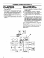
CONNECTIONS
STEP 1. MAKE BASIC CONNECTION
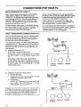
C.
Cable-TV
Connection
FOR YOUR TV
TO TV (CONTINUED)
to TV
If You Do Not Have a Converter/Decoder
O/3/4
OOfPlff
Box:
1.
Connect the 75-ohm cable-TV input directly to
the ANT/CABLE
I jack.
If You Have a Converter/Decoder
Box:
1.
Connect
2.
ANT/CABLE
2 jack on the TV.
Connect a 75-ohm cable from the LOOP OUT
jack on the TV to the IN jack on the decoder/
converter.
3.
the 75-ohm cable-TV
IN-I CONVERTER
DECODER!
I
input to the
•
CABLE-TV
_
z
T
I
I
Connect a 75oohm cable from the OUT jack on
the decoder/converter
to the ANT/CABLE
1
jack on the TV.
I'
)©
LOOP OUT
ANTICABLE 2
TO DECODER
D.
Cable-TV Connection to VCR and TV
If You Do Not Have a Converter/Decoder
1.
2.
3.
IF NO CONVERTER/DECODER
CH 3/4
Box:
OUTPUT
Connect the 75-ohm cable-TV input directly to
the ANT/CABLE
2 jack.
Connect a 75-ohm cable from the LOOP OUT
jack on the TV to the antenna IN jack on the
VCR.
CONVERTER
DECODER/i_I
__
Connect a 75-ohm cable from the antenna OUT
jack on the VCR to the ANT/CABLE
1 jack on
the TV.
If You Have a Converter/Decoder
or
Box:
1.
Connect the 75-ohm cable-TV input directly to
the ANT/CABLE 2 jack.
2a. (_onnect a 75-ohm cable from the LOOP OUT
jack on the TV to the IN jack on the decoder/
converter.
LOOP OUT
2b. Connect a 75-ohm cable from the OUT jack on
the decoder/converter
to the antenna IN jack
on the VCR.
3.
TO DECODER
Connect a 75-ohm cable from the antenna OUT
jack on the VCR to the ANT/CABLE
1 jack on
the TV.
NOTE:
If you have a stereo VCR, you must make the A/V
connections
described in Step 2 for you to hear stereo
sound while playing a tape.
258o
t-_ll
1-3
ANT/CABLE 2
I
I
ANT/CABLE 1
CONNECTIONS
STEP 2. MAKE VCR CONNECTIONS
FOR YOUR TV
TO TV
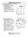
STEREO VCR
STEREOVCR
Connections: You must make the following connections to
obtain stereo sound from your TV while playing a stereo
video tape.
1. Connect the VCR Right/Left
AUDIO OUTPUT
into the VIDEO 1 IN Right and Left audio.jacks on
the TV.
2. Connect VCR VIDEO OUTPUT into the VIDEO
1 IN VIDEO jack on TV.
_
R
L
,o a _c-
0
Operation: To use these VCR connections, VIDEO I must
be selected from the SOURCE MENU. To select this source,
refer to the SOURCE MENU section of this booklet. For improsv.d picture quality, place VCR/TV switch on your VCR in
the VCR position.
VIDEO 1 IN
VIDEO
-0
MONAURAL VCR
MONAURALVCR
I
Connections:
1.
2.
To get monaural sound from both TV speakers, use
a Y-adapter
audio cable (customer
supplied) to
route VCR AUDIO OUT to the VIDEO 1 IN Right
and Left audio jacks on the TV.
Connect VCR VIDEO OUTPUT into the VIDEO
1 IN VIDEO jack on TV.
OUTPUTS I
I VIDEO
AUOIO
I
,o
dVIDEO
-0 VV
z_
1-4
CONNECTIONS
STEP 3. MAKE SUPER-VHS
FOR YOUR TV
VCR CONNECTIONS
In addition to the video connections already described, your
TV is also capable of using a Super-VHS VCR as a video
source. Refer to the illustration below.
t.
TO TV
2.
Connect the Right and Left AUDIO Output from
the Super-VHS VCR to the Right and Left (Audio)
S-VIDEO INPUT jacks on the TV. (These audio
connections must be made in order to receive sound
from the VCR.)
NOTE: Make sure S-VIDEO I is selected in the SOURCE
Menu to view this source.
Connect the Y/C-VIDEO
Output cable from the
Super-VHS
VCR to the S-VIDEO Y-C jack on the
TV.
SUPER VHS
STEREO VCR
0
VIOEO 1 IN
0
I
R
L
INI'___INI"
VIDEO 2 IN
( uoo©
0
VIDEO
R
L
S-VIDEO 1 IN
0 O0
LOOPOUT
,__o
Y/C VIDEO
OUT
Rl_fr
TO EXTERNALAMP
SPEAKERS
LOOPOUT ANTK_ABLE
2
TO DECOOER
ANT/CABLE1
VIDEO
I
AUOIO
OUT
4-
T
S-VIDEO
R
1-5
L
EXTERNALSPKRS
CONNECTIONS FOR YOUR TV
STEP 4. MAKE STEREO
AUDIO CONNECTION
TO AUDIO AMPLIFIER
Using an External Amplifier with Speakers While the TWs
Speakers are OFF
Using an External Amplifier with Speakers While the TWs
Speakers are ON
1.
1.
2.
3.
Make the connections to the external amplifier as
shown in the diagram below.
Place the SPEAKER EXT/INT switch on the TV in
the INT position (TV's speakers are ON).
Turn the TV ON. Increase the volume level of the
TV until the sound just starts to distort (sound
bad).
4.
Place the SPEAKER EXT/INT switch on the TV in
the EXT position (TV's speakers are OFF).
5.
Turn the external audio amplifier ON. Adjust the
volume level of the audio amplifier for the highest
level you will need for your listening pleasure.
6.
7.
2.
3.
Adjust the volume level of the TV for the normal
listening level as heard through the speakers of your
audio amplifier.
You can now use the VOLUME control on the TV
or on the remote control to adjust the volume of the
speakers of your audio amplifier.
Make the connections
to the external amplifier as
shown in the diagram below.
Place the SPEAKER EXT/INT switch on the TV in
the INT position (TV's speakers arc ON).
Turn the TV ON. Increase the volume level of the
TV until the sound just starts to distort (sound
bad).
4.
Turn the external audio amplifier ON. Adjust the
volume level of the audio amplifier for the highest
level you will need for your listening pleasure.
5.
Adjust the volume level of the TV for the normal
listening level as heard through the speakers of the
TV.
6.
You can now use the VOLUME control on the TV
or on the remote control to adjust the volume of
both the TV's speakers
and the audio amplifier's
speakers.
NOTE: If the volume of the internal TV speakers is set too
low, you may hear undesirable noises through the speakers
connected to your audio amplifier.
I AUX INPUT
SPKR OUTPUT
0
JACK PANEL ON
STEREO AMPLIFIER
0
LOOP OUT
TO DE_R
ANT/CABLE2
RIGHT
LEFT
SURROUND
TO EXTERNALAMP
SPEAKERS
SPEAKER
_q3'/C/U31.E1
VIDEO 1 IH
o ©"©0
VIDEO
0
[-]
VIDEO 2 IN
E
F
VIDEO
I =I
000
LOOP OUT
[-1 :
R
L
S-VIDEO I IN
000
S-VlOEO
1-6
D
R
L
EXTERNAL SPKRS
I
G
H
T
÷
CONNECTIONS
FOR YOUR TV
STEP 5. TV CONNECTION
TO EXTERNAL SPEAKERS
STEP 6. "rv CONNECTION TO
SURROUND SOUND SPEAKERS
1.
I.
2.
3.
4.
Place the SPEAKERS switch on the back of the TV
in the INT position.
Connect the two external speaker terminals. Observe polarity of the connections; silver speaker
wire to the red terminal and copper speaker wire to
the black terminal. Use 8-ohm speakers only.
Place the SPEAKERS switch on the back of the TV
in the EXT position.
Use the VOLUME control on the TV or on the
remote control to adjust the volume of the external
speakers.
2.
3.
4.
5.
Mount and connect the optional Surround Sound
speakers by following the instructions provided
with the speakers.
In the AUDIO Menu, set the TV to STEREO.
Use the SURROUND option in the AUDIO Menu
to adjust the volume of the surround speakers.
Use the VOLUME control to adjust the volume of
the TV.
The level of the Surround sound varies relative to
the difference between the left- and right-channel
stereo signals. The degree of the Surround sound
effect depends on the program source you are
using. Some sources, especially video tape, provide
greater sensation of Surround sound than may be
obtained from a standard TV broadcast.
NOTE: The surround jack is always active. Therefore, the
position of the speaker switch does not affect the operation
of surround speakers.
CAUTION: The Surround Sound output has an 8-ohm system impedance. It is for use with two 16-ohm speakers connected in parallel. Use of non-surround speakers may
damage your TV.
IS ohm
I
16 ohm
Phono
SURROUNDSOUNO
SPEAKERS
8ok'n System
Impedance
©©
RIGHT
LEFT
TO EXTERNAL AMP
U
P_
SURROUND
SPEAKER
SPEAKERS
/U_'/C/UBLE1
i
VIDEO 1 IN
.
SILVER
Left
VIDEO 2 IN
VIDEO
©
8 ohm
R
L
S-VIDEOI IN
©© ©©
LOOPOUT
2s8o
S-VIOEO
Q
R
L
1-7
D
I-I
I1o_
li L
EXTERNAL SPKRS
l
Right
Speak_
Sohm
CONNECTIONS
STEP 7. AN CONNECTION
TO FRONT AN JACKS (Some
FOR YOUR TV
Models)
Some models of TVs are equipped with an additional set of
audio and video jacks on the front of the TV. These are
provided primarily as a convenience for connecting a video
Camcorder. However, they are just as useful in connecting
VCRs or Video disc players. In addition, a Super-Video
(Y-C) jack is also provided.
VIDEO 3 IN
0--0
LEFT
To connect a S-Video VCR to these jacks:
1.
Connect the Y/C-VIDEO
Output cable from the
Super-VHS VCR to the S-VIDEO 2 Y-C jack.
2.
Connect the Right and Left AUDIO Output from
the Super-VHS VCR to the Right and Left AUDIO
INPUT jacks.
(These audio connections
must be
made in order to receive sound from the S-VHS
VCR.)
To connect a camcorder to these jacks:
2.
Connect the camcorder Right/Left
AUDIO OUTPUT into the VIDEO 3 IN Right and Left audio
jacks on the TV.
Connect
camcorder
VIDEO OUTPUT
into the
VIDEO 3 IN VIDEO jack on TV.
Operation: To use these VCR connections, VIDEO 3 must
be selected from the SOURCE MENU.
25_
RIGHT
AUDIO INPUT
NOTE: Make sure S-VIDEO 2 is seleaed in the SOURCE
Menu to view this source. To select this source, refer to the
SOURCE MENU section of this booklet.
1.
S-VIDEO 2 IN
1-8
VIDEOINPUT
THE FIRST TIME YOU OPERATE YOUR TV
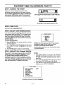
STEP 1. CONNECT
THE POWER
Plug your "IV into an unswitched AC power source.
The switched AC outlets found on some video equipment
will not continue supplying power to the TV once the equipment is turned off. If the power to the TV is interrupted,
you will have to set the dock in the TV to the current time.
Do not plug TV into switched outlet on cable-TV decoder.
Do not plug TV into switched outlet on a VCR.
STEP 2. TURN
TV ON
Turn the TV ON by pressing OFF-ON.
STEP 3. SELECT
YOUR VIEWING
SOURCE
A TV source refers to the equipment connected to the connection center on the back of your TV. For example, antenna, cable-TV, VCR, video disc player, etc. You can select
what source supplies the picture and sound to your TV by
pressing SOURCE on your remote control and viewing the
SOURCE MENU.
_SOURCE
ANT/CABLE 1
ANTICABLE 2
VIDEO 1
VIDEO 2
S-VIDEO 1
To Access SOURCE MENU
1.
.
3.
Press SOURCE on the remote
SOURCE MENU.
Press SOURCE
na or cable-TV
ENTER.
control
to view the
NOTES: The correct antenna or cable-TV source must be
selected before STEP 4 in order for the AUTO CH.
SEARCH to correctly find available channels
For information about sources, see "Source Menu" section
of this operating guide.
repeatedly
until the correct antensource is highlighted,
then press
Press ENTER again to return to normal viewing.
STEP 4. USE AUTO CH. (Channel)
SEARCH
NOTES:
When your TV is fh'st powered up, you will see the SETUP
MENU with AUTO CH. SEARCH highlighted. AUTO
CH. SEARCH finds all available channels from the
selected source and stores them in memory for access by
CHANNEL Up/Down. To activate AUTO CH. SEARCH,
press ADJUST (ADJ) Left/Right. When the search is complete, you aan watch the TV program of your choice.
1.
The SETUP MENU with AUTO CH. SEARCH
highlighted will appear each time you turn on your
TV until AUTO CH. SEARCH
has been used at
least once.
2.
The AUTO CH. SEARCH message appears only if
one of the ANT/CABLE
sources is selected.
3.
Your antenna or cable must be connected
before you use AUTO CH. SEARCH.
SETUP MENU
•.> AUTO CH. SEARCH
CH. ADD/DEL
CH. LABELS
TUNING BAND
AUTO FINE TUNE
CLOCK SET
CAPTIONS
CH. BACKGROUND
START
Setup Menu with Auto Ch. Search Highlighted
258o
MENU_
2-1
to the TV
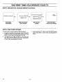
THE FIRST TIME YOU OPERATE YOUR TV
STEP
4. USE AUTO
CH.
(Channel)
SEARCH
(CONTINUED)
ALr_
DE'!ERMINING
TUNING
BAND
TUNING
BAND
C_£ SEAI_
TUNING
D
BAND
STEP 5. USE OTHER
FOUND
When Search is
Complete
While Searching for
Active Channels
When Returning to
Channel/Audio Display
OPTIONS
set the clock in the TV. Refer to the CLOCK SET option
of the "Setup Menu" section of this operating guide for
details.
You may want to consider using the following options:
•
Program the channels accessed when using CHANNEL
Up/Down. Refer to CH. ADD/DEL option of the "Setup
Menu" section of this operating guide for details.
•
Add labels (such as NBC and ABC) to the channel display. Refer to CH. LABELS option of the "Setup Menu"
section of this operating guide for details.
25ao
IS
IS FOUND
DCHANNELS
Determining
Tuning Band
CH 2
STEREO
IS
--4P
CH
HAS COMPI._
2 -2
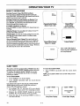
OPERATING YOUR TV
BASIC TV OPERATIONS
r
Selecting Channels Using CHANNEL Up/Down:
You may select a channel through channel scanning by
using CHANNEL Up/Down keys. Only channels stored in the
channel scan sequence can be selected.
.
CH 2
10:56
STEREO
CH2
STEREO
Selecting Channels by Using Numbers on Remote: Press
the numbers corresponding to the channel desired, then
press ENTER. Any channel in the band chosen can be
selected through direct number entry.
J
Cbannel/Time/
Audio Display
(After Clock is Set)
Channel/Audio Display
(Before Clock is Set)
FLASHBK (Flashback) on Remote:
Press FLASHBK to return to the last TV channel you were
watching.
f
Adjusting Volume: You can adjust the volume of your TV
by using VOLUME Up/Down.
CH2
10:56
MUTED
Muting Volume: To mute the sound coming from your TV,
press MUTE on the remote control. To restore sound,
press MUTE again.
VOL
After an Extended Power Outage: If you previously used
AUTO CH. SEARCH, you do not have to use it again unless you permanently changed the connections to the TV.
All of the channels previously found are stored in protected
memory, and are not affected by a power outage. However,
the clock must be reset to the current time.
_Channel/Time Displa;
While TV is Muted
Volume Display *
VOL or MUTED display is
shown only when captious are
not being displayed.
MUTED
J
Mute Display *
SLEEP TIMER
To Cancel the SLEEP TIMER
The remote control is equipped with a TIMER button that
provides access to the SLEEP TIMER available with some
TV models. By using the SLEEP TIMER, you can program the TV to automatically shut off after a 15 minute
period up to 4 hours.
To Set SLEEP TIMER
1.
Press
TIMER
2.
Press TIMER
shut-off time.
to see status
repeatedly
1.
o
3.
2sso
TIMER
repeatedly
until
the
status
shows
NOTE: The SLEEP TIMER resets to OFF when you turn
off the TV.
display
until
you reach
desired
One minute before the TV shuts off, the GOOD NIGHT
display appears on the screen. At this time you have a
choice of the following three actions.
1.
Press
OFF.
vSLEEP
MER
vS
EME
P
Do nothing. The TV will turn off in one minute.
The display "counts down" the remaining seconds.
Remove the GOOD NIGHT display by pressing
ENTER. The TV will still shut off in one minute.
Delay the shut off by pressing
new shut-off time.
TIMER
to select
0:]5
a
Sleep Timer Display
3-1
GOOD NIGHT
0:58
"Good Night" Display
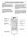
GETTING TO KNOW YOUR TV
FRONT
PANEL
CONTROLS
Refer to the illustration below while reading the descriptions of the TV controls.
ENTER
• ADJUSTI*
SELECT
OI
1.
MENU
4,VOLUMEv
O
3.
ENTER
1
,
menu operations
to select a
Press once to see a menu. Press repeatedly
quence through the available menus.
zsso
6.
ADJUST (ADJ) Left/Right or ,/j_
Press during on-screen
menu operation
to see information/status
display for selected option. Press
again to adjust the selected menu option.
SELECT
Press during on-screen
menu option.
MENU
OFF/ON
CZ) CZ)
Press to see the Channel/Time
display, or to remove
any on-screen
display or menu.
2.
ACHANNELv
o
8.
to se-
4 -1
VOLUME Up/Down
Press to increase or decrease
the sound
level.
CHANNEL Up/Down
Press to select channels
higher or lower than the
channels being viewed. You can also add channels or
delete channels from the scanning sequence stored in
memory. See CH. ADD/DEL
option of the "Setup
Menu" section of this operating guide for channel
programming
information.
OFF-ON
Press to turn TV power ON or OFF.
Remote Control Detector Window
Point the remote control towards this window
operate the TV.
to
GETTING TO KNOW YOUR REMOTE CONTROL
OPERATION
Your multi-brand remote has already
operate your new Zenith TV, a Zenith
TV decoder and a Zenith VHS VCR.
programmed to operate other brands
The multi-brand remote control supplied with your new
Z,enith TV allows you to operate most models of infrared
(IR) remote-controlled
TVs, VCRs and cable-TV
decoders, even if they are all different brands. In this way,
it takes the place of the several remote controls previously
needed.
CHOOSE
THE OPERATING
been programmed to
manufactured
cableIt must be
of equipment.
The following instructions are for the operation of Zenith
equipment. The instructions for using this remote with nonZenith equipment are in the section entitled "Programming
Your Remote Control."
MODE
Some controls on the remote, like PLAY and VOLUME,
will always operate the VCR or the TV. Whether other keys
operate the TV or VCR depends on which mode of operation the remote control is in. For example, OFF-ON will
turn the VCR on and off while the remote control is in the
VCR mode. It will turn the TV on or off while the remote
control is in TV mode.
To use the remote to operate your TV, CABLE-TV
decoder or a VCR, you must first choose the mode of
operation of the remote. To select TV, CABLE or VCR
mode, press the MODE key until the corresponding indicator lights.
Operating MODE switch
and indicators
f--_q f-_-q
OFT ON I
f
Menu operations on TV
and some VCRs
i
SELECT
device OFF/ON
Special features on TV and
some VCRs
0
QUIT
@®®
CHANNEL
®®®
®®®
Channel Up/Down for TVs,
VCRs and cable
VOLUME
Volume Up/Down for TV
C::D C=D
C:D
A
_
B
C:::D
IdEMOl_'
CD
MUTE
C:D
TIMER
C:=D C]D
C:K:) C_D
C_ED (:_D
(::3ED CZD
Special features on some
TVs and some VCRs
SEARCH
I_W
PLAY
F FWD
I'V/VCR
NOTE: See following pages
for operating instructions.
£
MBR3420
:_8o
Controlled
SOURCE
,0J.[]
Numbered buttons for
channel selection and
other uses
t
5-1
GETTING TO KNOW YOUR REMOTE CONTROL
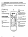
"IV OPERATIONS
The following funct2ons and operations apply to your
Zenith TV. The remote control must be in the TV mode to
operate your "IV.
MODE
The VOLUME control will always adjust the "IV volume
regardless of the selected operating
mode of the remote.
!
Press repeatedly to select the "IV
mode of operation.
'IV
Lights when "IV mode of
operation is selected.
For optimum performance, point the
remote control toward your TV.
OFF/ON
Used to turn TV ON or OFF.
SOURCE
Press to display the menu of TV sources for TVs having a SOURCE Menu.
Press SOURCE again to step through
the source selections. On some TVs,
press SOURCE to select the AUX
(Auxiliary) channel.
CAPTIONS
Used to view closed captions broadcast
with some television programs.
FLASHBK (Flashback)
Press to return to the last TV channel
you were watching.
MENU, SELECT and ADJUST
Used with on-screen menus to see menu,
select an option, and adjust that option.
CHANNEL Up/Down
Used to sequence through the TV channels.
Press CHANNEL Up or Down to change
to the next higher or lower channel
Numbered Buttons
Used to select a TV channel.
VOLUME Up/Down
ENTER
Used to adjust the volume level of the TV.
Used to view the Chaunel/Tune Display
or to remove any on-screen menu or
MUTE
display.
Used to turn off sound while the picture remains. Press again to restore
the sound.
TIMER
SPACIAL EQUALIZATION (SEq)
Used to activate the SLEEP TIMER.
Used to select SEq audio mode on TVs
equipped with SEq feature.
4
Remote Control MBR3420
TV Operations
2580
5-2
GETTING TO KNOW YOUR REMOTE CONTROL
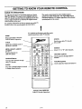
VCR OPERATIONS
The following functions and operations apply to Zenith
VCR models builtafter 1988.The remote control suppfied
with yourVCR may have keys not duplicated on the new
remote. If these functions are desired, the original remote
control will have to be used.
For complete details on how to operate your Zenith VCR,
refer to the operating guide supplied with it.
The remote control must be in the VCR mode to operate
your VCR.
For optimum performance, point the
remote control toward your VCR.
MODE
Press repeatedly to select the
VCR mode of operation.
OFF/ON
VCR
Used to turn VCR ON or OFF.
Lights when VCR mode of operation
is selected.
MENU, SELECT, ADJUST and QUIT
Used with the on-screen menus and
programmingoptions of the VCR. See
VCR operatingguide for details
FLASHBK (Flashback)
t
Press during VCR playback to view the
channel tuned by the VCR.
CHANNEL Up/Down
Numbered Buttons
Used to select a TV channel through
the VCR. Also, used to set the timer in
the VCR, and to enter programming
information.
_
TIMER
Activates TIME RECORD
some VCRs.
ENTER
Used with the numberedbuttons to
select a TV channelthroughthe VCR.
AM/PM
Used to select the source of the
programs seen on the TV. Switches the
VCR between TV mode and VCR
mode. TV Mode: channels are selected
through the TV. VCR Mode: channels
or tape operation are selected through
the VCR.
/
MEMORY
J
I
RECORD, STOP, PAUSE, SEARCH,
REW, PLAY and F FWD
Remote Control MBR3420
VCR Operations
Used for tape recording and playback
functions. See the VCR operating guide
for details.
_so
on
TVNCR
Used to set timer during programming.
Used to activate the VCR MEMORY
feature. See VCR operating guide for
details.
Up or Down through channels l_om the
VCR.
Used to select a TV channel bygoing
5-3
GETTING TO KNOW YOUR REMOTE CONTROL
CABLE-TV
OPERATIONS
The remote control must be in the CABLE mode to
operate your cable-TV decoder. The VOLUME control
will always adjust the TV volume regardless of the selected
operating mode of the remote.
The following functions and operations apply to a Zenith
cable-TV decoder. The remote control supplied with your
cable-TV decoder may have keys not duplicated on the new
remote. If these functions are desired, the original remote
control will have to be used.
For complete information on how to operate your cable-TV
decoder, refer to the operating guide provided with it.
MODE
For optimum performance, point the remote
control toward your cable-TV decoder.
Press repeatedly to select the
CABLE mode of operation.
OFF/ON
Used to turn cable-TV decoder
CABLE
Lights when CABLE mode of
operation is selected.
ON or OFF.
SOURCE
MENU, SELECT, ADJUST
and QUIT
Function depends on
cable-TV system.
Numbered Buttons
Used to select channels thl.ough
cable-TV decoder
Selects "A" or "B" cable channels.
_J.
[]
SELECT
CHANNEL Up/Down
QUIT
®®®
®®®
®®®
Used to sequence through cable-TV
channels.
VOLUME Up/Down
Used to adjust the volume level of the TV.
ENTER
Press after a channel number is entered
to change channel instantly.
J
Remote Control
Cable-TV
25_o
Decoder
5-4
MBR3420
Operations
GETTING TO KNOW YOUR REMOTE CONTROL
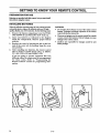
PREPARATION
FOR USE
Batteries are providedwith this remote, but you must install
them before using the remote.
INSTALLING
BA'I-rERIES
CAUTIONS:
When the effective operating range of your remote becomes
noticeably shorter, replace the batteries with two (2) high
quality, alkaline, size AAA batteries. Do the following steps:
•
Do not place heavy objects on top of the remote control
buttons. Prolonged accidental operation of the remote
control will shorten battery life.
1.
Remove the battery compartment
cover by PUSHING DOWN tab and PULLING
OUT from top.
•
2.
Insert new batteries
as indicated
inside the compartment.
Observe
polarity.
If you are not going to use the remote control for a month
or more, remove the batteries. Battery leakage can cause
damage to the remote control.
•
3.
Replace the cover by inserting the tab on the bottom of the cover into its housing. Snap the cover
into position.
Zenith is not responsible
battery leakage.
4.
.i_fter installing new batteries,
the remote control
will set itself to Zenith brand codes, as follows:
TV = 101, VCR = 201 and CABLE = 301.
in the diagram
proper
battery
for damage caused by such
If you are going to operate
equipment
that uses
different codes, the remote must be reprogrammed
for those codes.
Refer to "Programming
the
Remote Control"
section for programming
information.
11
2._
11
5-5
1
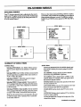
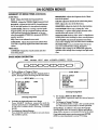
ON-SCREEN MENUS
AVAILABLE
MENUS
There are four basic menus: SOURCE, SETUP, AUDIO,
and VIDEO. These menus list everything you can adjust to
your personal preference or needs. In addition, separate
SOURCE and VIDEO menus appear for PIP while PIP is
active.
Your TV is menu operated, that is, adjustmentsthat can be
made to the "IVappearon the screen in a list of choices you
can make by using the controls on the front panel of the TV
or on the remote control.
SETUP MENU
SOURCE MENU
•._ AUTO CH. SEARCH
CH. ADD/DEL
CH. LABELS
TUNING BAND
AUTO FINE TUNE
CLOCKSET
CAPTIONS
CH. BACKGROUND
-> ANT/CABLE1
ANT/CABLE2
VIDEO 1
VIDEO 2
S-VIDEO 1
VIDEO 3
S-VIDEO 2
START
I
VIDEO MENU
AUDIO MENU
-> BASS
TREBLE
BALANCE
AUDIO
SEO
SURROUND
SUMMARY
OF MENU
-
!
I
I
STEREO
ON
...>CONTRAST
BRIGHTNESS
COLOR
TINT
SHARPNESS
COLOR TEMP
VIDEO FILTER
AUTO FLESH
PICTURE PREF
+
+
+
"'=
_lit
4.
--_
--llll
4.
4.
G
_l_=
I
R
4.
COOL
ON
OFF
CUSTOM
ITEMS
SETUP Menu
SOURCE Menu
Selecting ANT/CABLE 1 or 2: Either of these sources
may be used for input from an antenna or a cable-TV
line.
AUTO CH. SEARCH: Finds all available channels and
stores them in memory for access by using CHANNEL
Selecting VIDEO I or 2: Either of these sources may be
used for input from an auxiliary video source such as a
VCR or aWideo disc player.
CH. ADD/I)EL: Changes the list of active channels
selected by using CHANNEL Up/Down.
Selecting S-VIDEO 1: Select this source if a SuperVI-IS VCR is connected to your TV.
channel display. For example, ABC may appear when
this network channel is tuned.
Selecting VIDEO 3 (Some models): If your model of
TV is equipped with front A/V jacks, select this source
if a camcorder or other video component is connected
to the front jacks.
TUNING BAND:. Determines
nel tuner inside the TV.
Selecting S-VIDEO 2 (Some modds): If your model of
TV is equipped with front A/V jacks, select this source
if a Super-VHS VCR is connected to the front jacks.
CLOCK SET: Sets the clock in the TV to the correct
time.
Up/Down.
CH. LABELS: Adds a channel name "LABEL"
the operation
to the
of the chan-
AUTO FINE TUNE: Lets your TV compensate
tions in broadcast and cable-TV frequencies.
for varia-
CAPTIONS: Displays closed captions (CC) or informational text when available.
Make sure the selected source corresponds to the jack
to which the input cable or antenna wire is connected
on the back of the TV.
CH. BACKGROUND: Changes the background
channel/time display.
of the
(continued on next page)
2500
6-1
ON-SCREEN
SUMMARY
OF MENU
ITEMS
MENUS
(CONTINUED)
BRIGHTNESS: Adjusts the brightness level of black
areas in the picture.
AUDIO Menu
BASS: Adjusts the BASS (low frequency) level.
TREBLE: Adjusts the TREBLE (high frequency)
COLOR: Adjusts the intensity of the colors in the picture.
level.
BALANCE: Adjusts the BALANCE of sound between
the leR and right speakers for stereophonic programs.
TINT: Adjusts the color of the flesh tones.
AUDIO
COLOR TEMP: Allows you to change the "color
temperature" or picture white balance between cooler
natural whites and warmer (red) colors.
MODE:
Allows for receiving
a Second
SHARPNF__S: Adjusts the clarity for the clearest picture.
Audio
Program (SAP), such as a program broadcast with two
audio portions (typically two languages), or lets you
select stereophonic (STEREO) or monaural (MONO)
speaker operation.
VIDEO FILTER: Reduces video "noise" or interference
in dark picture areas resulting in clearer overall pictures.
SEQ:. Turns on an enhanced stereo mode.
AUTO FLESH: Automatically maintains natural skin
tones under changing scene and video source conditions.
SURROUND: Adjusts Surround Sound volume when
used with a separately supplied Surround Sound audio
system.
PICTURE PREF: Lets you decide if you want to use
your own CUSTOM video settings, the factory
PRESET video settings or the THEATER option for
optimum video settings when viewing in low-light conditious.
VIDEO Menu
CONTRAST: Adjusts the overall contrast and color
level of the picture.
BASIC MENU OPERATION
ENTER
• ADJUSTI_
SELECT
MENU
A_UUMEV
ACHANNELv
OFF/ON
(
To See a Menu or Change a Menu:
Press MENU repeatedly until the desired menu is
shown. Example shows choosing the SETUP Menu.
Xe
SETUP MENU
AUTO CH. SEARCH
CH. ADD/DEL
CH. LABELS
•">TUNING BAND
AUTO FINE TUNE
CLOCK SET
CAPTIONS
CH. BACKGROUND
SETUP MENU
•_ AUTO CH. SEARCH
CH. ADD/DEL
CAl. LABELS
TUNING BAND
AUTO FINE TUNE
CLOCK SET
CAPTIONS
CH. BACKGROUND
Choosing
.
.
2580
START
Selecting Tuning Band
4.
Setup Menu
To Select an Option/Feature
on a Menu:
Press SELECT
Up/Down
repeatedly
until the
desired option/feature
is highlighted.
The example
in the next column shows selecting
TUNING
BAND.
To Adjust an Option/Feature:
Press ADJUST (ADJ) Left/Right
the available options.
CABLE-CA'rV
To Access a Different Main Menu:
Press MENU repeatedly until the desired
shown.
menu is
5.
To Return toNormal Viewing:
Press ENTER (ENT) or wait a few seconds and the
TV will return automatically to normal operation.
Service Menus: In addition to the menus shown in this
operating guide, there are menus for factory and field servicing. Service menus are not intended for use by the owner.
to see and choose
If you inadvertently access a service menu, press ENTER
(ENT) to return immediately to normal TV viewing.
6-2
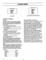
SOURCE MENU
_SOURCE
ANT/CABLE1
ANT/CABLE2
VIDEO 1
VIDEO 2
S-VIDEO t
VIDEO 3
S-VIDEO 2
.._ ANT/CABLEt
ANT/CABLE2
VIDEO 1
VIDEO 2MENU
SOURCE
S-VIDEO 1
Source Menu for TVs with Front Jacks
Source Menu
TO SELECT
MENU_
A SOURCE
PURPOSE
SOURCE EQUIPMENT CONNECTIONS
The SOURCE MENU is used to specify the equipment
that is being used to supply the video and audio signals.
You select the source you want by selecting the SOURCE
MENU. It shows the possible sources available for your
viewing selection.
To Access the SOURCE MENU Directly
The actual source selected for viewing on your TV depends
on how the TV is connected to external equipment.
Selecting ANT/CABLE 1 or 2 from SOURCE Menu:
Routes the ANTENNA or cable-TV source to the TV for
viewing. You see program material from whichever signal
source is connected to the ANT/CABLE
jack. Usually the
antenna is connected to the ANTENNA jack. In cable applications, the output from a cable-TV decoder is connected to this jack. For VCR application, the ANT OUT
from the VCR is connected to this jack.
1. Press SOURCE on the remote control to bring up the
SOURCE MENU.
2. Press SOURCE repeatedly until the source you want is
highlighted.
3. Press ENTER to return to normal viewing.
Selecting VIDEO 1 or 2 from SOURCE Menu: Routes the
auxiliary video source (such as a VCR or a Video Disc
player) to the TV for viewing. The video source must be
connected to the corresponding VIDEO 1/2 jacks.
To Access the SOURCE MENU Indirectly
1. Press MENU until the SOURCE Menu is displayed.
Selecting S-VIDEO 1: Routes the auxiliary Super-VHS
VCR Source to the TV for viewing. The Super-VHS VCR
must be connected to the corresponding input jacks.
2. Press SELECT Up/Down until the desired source is
highlighted.
3. Press ENTER to return to normal viewing.
Selecting VIDEO 3 from SOURCE Menu: Routes the front
video source (such as a camcorder, VCR or a Video Disc
player) to the TV for viewing. The video source must be
connected to the corresponding VIDEO 3 jacks.
SOURCE IDENTIFICATION
The Channel/Time display is used to determine the type of
input source currently being viewed. To see the Channe!/
Time display, press ENTER. If an antenna or cable-TV
source is being viewed, the Chaune!/Time display is shown in
the Channel Number/Time format. If a Video source is being
viewed, the Channe!/Time display is shown in the Video/Time
format.
Selecting S-VIDEO 2: Routes the front Super-VHS VCR
source to the TV for viewing. The Super-VHS VCR must
be connected to the corresponding S-VIDEO 2 input jacks.
NOTE: The sources are identified by color in both the onscreen displays and on the connection center on the back of
the TV. The color for the Channel/Time display, Volume
and Muted display will match the color or the source you
are watching. The color will also help to identify which
source you are watching when viewing PIP. The colors are
as follows:
SOURCE
ANT/CABLE 1 .......................
ANT/CABLE 2 .......................
VIDEO 1 ............................
VIDEO 2 ............................
S-VIDEO 1 ..........................
VIDEO 3 ............................
S-VIDEO 2 ..........................
25s0
COLOR
RED
BLUE
MAGENTA
LT. BLUE
GREEN
YELLOW
WHITE
7-1
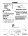
SETUP MENU
SETUP MENU
•'_ AUTO CH. SEARCH
CH. AOD/DEL
CH. LABELS
TUNING BAND
AUTO FINE TUNE
CLOCK SET
CAPTIONS
CH. BACKGROUND
START
SETUP MENU
•.> CL(XT,
K SET
CAPTIONS
CH. BACKGROUND
SETUP MENU for VIDEO and S-VIDEO SOURCES
SETUP MENU
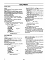
AUTO CH. (Channel)
SEARCH
3.
Use AUTO CH. SEARCH only when you first install your
TV, or when you permanently change the connections to
the TV. For example, when you replace the antenna with a
cable-TV system.
Use the AUTO
CH. SEARCH
feature
independently for each ANTENNA
or CABLE signal
source connected to your TV. Select one source by
using the SOURCE MENU (ANT/CABLE
1 or 2)
and use AUTO CH. SEARCH. When completed,
select
the other source
and use AUTO CH.
SEARCH again.
When Some Channels Are Not Found
Before Using AUTO SEARCH
Connect and turn ON all external equipment, such as a
cable-TV decoder, VCR, etc.
AUTO CH. SEARCH finds only active channels and stores
them in its channel memory. You can add channels to those
stored in memory by using the CH. ADD/DEL option.
Purpose
Finds all available channels and stores them in memory for
access by CHANNEL Up/Down.
NOTE: AUTO CH. SEARCH can only be used with ANT/
CABLE I or 2 source selection.
If you have difficulty tuning some channels, you may have to
manually change the BAND SELECT and AUTO FINE
TUNE mode. Refer to respective option for details.
To Use AUTO SEARCH
1. AUTO CH. SEARCH should be selected if you
followed the "Basic Menu Operation" given in the
"On-Screen Menu" section.
2. Press ADJUST (ADJ) Left/Right to start the
AUTO CH. SEARCH. The status of the search is
shown in the display. When the search is complete,
you can watch the TV program of your choice.
NOTE: If the output from a cable box is the input to your
TV, the only active channel will be either 3 or 4.
SETUP MENU
-> AUTO CH. SEARCH
CH. ADD/DEL
CH. LABELS
TUNING BAND
AUTO FINE TUNE
CLOCK SET
CAPTIONS
CH. BACKGROUND
Selecting
START
Auto Ch. Search
CH2
STEREO
AUTO Ctt SEARCH HAS COMPLEIE_
DETERMINING
TUNING
BAND
TUNING
BAND
IS
TUNING
,,,--4P
CH 1_1
BAND
IS
IS FOUND
DCHANNELS
FOUND
..
J
Determining
Tuning Band
2ss0
When Search
While Searching for
Active Channels
Complete
8-1
is
J
When Returning to
Channel/Audio Display
SETUP MENU
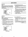
CH. (Channel)
ADD/DEL
To Add a Channel to Scan Sequence
Purpose
Lets you add channels to and remove channels from the acfive channels found by the AUTO CH. SEARCH option. In
this way, you can customize the channels that are accessed
through CHANNEL Up/Down.
CH. ADD/DEL is an optional feature. You do not have to
activate this feature in order to use your TV.
Before Using CH. ADD/DEL
Use the AUTO CH. SEARCH feature, if not previously
used when youfirst
installed the TV.
CH. (Channel)
2.
Use the numbered buttons to access channels
presently stored in the channel scan sequence.
3.
Add channel
by pressing
ADJUST
(ADJ)
Left/Right until the display shows ADD.
Press ENTER to return to normal TV viewing.
not
To Delete a Channel from Scan Sequence
1. CH. ADD/DEL
should be selected if you followed
the "Basic Menu Operation"
given in the "OnScreen Menu" section.
2.
SETUP MENU
Selecting
CH. ADD/DEL
should be selected if you followed
the ."Basic Menu Operation"
given in the "OnScreen Menu" section.
4.
NOTE: CH. ADD/DEL can only be used with ANT/
CABLE I or 2 Source selection.
AUTO CH. SEARCH
-'>CH. ADD/DEL
CH. LABELS
TUNING BAND
AUTO FINE TUNE
CLOCK SET
CAPTIONS
CH. BACKGROUND
1.
Using CHANNEL(CH)
nel you wish to remove.
Up/Down
go to the chan-
3.
Remove
channel by pressing
ADJUST
(ADJ)
Left/Right until the display shows DEL.
4. Press ENTER to return to normal TV viewing.
When Some Channels Can Not Be Tuned
If you have difficulty tuning some channels, you may have to
manually set the TUNING BAND option. If you have the
correct band, but are still having difficulty finding a channel
you know to be active, set the AUTO FINE TUNE to
SEARCH.
CH 13 ADD
Ch. Add/Dei
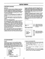
LABELS
Purpose
A&E
ABC
ACTS
ADC
AMC
BET
This option allows you to show a channel "name" each time
the channel display appears on the TV. In other words, if
you choose the label "ABC" for channel 13,"ABC" appears in the Channe!/Time display. Therefore, you always
know what channel you are watching.
BRAV
CA
CBC
CBN
CBS
CMTV
CNBC
CNN
COM
CSPN
CIN
CTV
DIS
DISC
Et
ENC
ESPN
ET
EWTN
FAM
FNN
FOX
GALA
HBO
HN
HSE
HSN
IC
INSP
LIFE
The labels shown in the following table may be "assigned"
to channels.
MAX
MEU
MMT
MTV
NBC
NICK
NOS
PBS
PLAY
PTL
QVC
REQ
SC
SHOW
SIN
TBS
TBN
TLC
CH. LABELS is not displayed when an auxiliary video
source (Video 1, 2, 3 or S-Video 1 or 2) is being used.
TMC
TNN
TNT
TRAV
TSN
TWN
USA
VC
VCR
VISN
VJN
These labels are in the memory of the TV. You can not
make your own labels.
To remove an assigned channel label, select the one that
is "blank."
WGN
WTBS
WWOR
NOTES:
•
•
•
Selecting
z_0
YTV
To Use CH. LABELS
1.
CH. LABELS should be selected
if you followed
the "Basic Menu Operation"
given in the "OnScreen Menu" section.
2.
Using the number buttons
Down, select a channel.
3.
Press ADJUST
(ADJ) Left/Right
to sequence
through the available choices until the desired label
appears.
Press ENTER to return to normal TV viewing.
SETUP MENU
AUTO CH. SEARCH
CI-L ADD/DEL
-> O-I. LABELS
TUNING BAND
AUTO FINE TUNE
CLOCKSET
CAPTIONS
CK. BACKGROUND
VIII
CH 13 ABC
4.
Ch. Labels
8-2
or CHANNEL
Up/
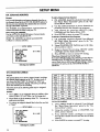
SETUP MENU
TUNING
BAND
2.
Purpose
Allows for setting the 'IV tuner to match your antennaor
cable-TV system.
If you used the AUTO CH. SEARCH feature, the proper
BAND was set automaticallyfor yourTV. If you did not use
AUTO CH. SEARCH, or you are having difficulty tuning
channels, the TUNING BAND may have to be set manually
to match yourviewing needs.
BeforeUsing TUNING BAND
Connect and turn ON all external equipment, such as a
cable-TV decoder, VCR, etc. Use CH. AUTO SEARCH,
if not previouslyused.
NOTE: TUNING BAND can only be used with ANT/
CABLE I or 2 Source selection.
1. TUNING BAND should be selected if you followed
the "Basic Menu Operation" given in the "OnScreen Menu" section.
BROADCAST
broadcasts.
•
Cable - CATV is used for most standard cable-TV
(CATV) systems.
•
Cable - HRC is used for cable-TV systems that use
HRC (Harmonically Related Carrier).
•
Cable - ICC is used for cable-TV systems using ICC
(Incremental Coherent Carrier).
*
is used for standard over-the-alr
Channels above 69 are not selectable.
CATV, HRC and ICC Bands
1 to 125"*
SETUP MENU
** Channels above 125 are not sele£table.
AUTO CH. SEARCH
CH. ADD/DEL
CI"L LABELS
"> TUNING BAND
AUTO FINE TUNE
CLOCK SET
CAPTIONS
CH. BACKGROUND
Tuning
•
Available Channels per Band
The channels that are available in the broadcast and cable
tuning bands are shown below:.
BROADCAST Band
VHF 2 to 13
UHF 14 to 69*
To Use TUNING BAND
Selecting
Press ADJUST (ADJ) Left/Right to select the
desired tuning baud, as shown below:
When Some Channels Are Not Clear
CABLE-CATV
If some channels are not dear, change the AUTO FINE
TUNE. You may have to try different TUNING BAND and
AUTO FINE TUNE combinations until you get a clear picture, channel-to-channel.
Refer to the AUTO FINE TUNE
option for details.
Band
AUTO FINE TUNE
Purpose
Lets your TV compensate
cable-TV frequencies.
NOTE: AUTO FINE TUNE can only be used with ANTI
CABLE 1 or 2 Source selection.
for variations in broadcast agd
To Use AUTO FINE TUNE
ff you are having difficulty tuning channels, the AUTO
FINE TUNE may have to be set manually to match your
viewing needs.
1.
Before Using AUTO FINE TUNE
2.
Connect and turn ON all external equipment,
TV decoder, VCR, etc.
Press ADJUST
(ADJ) Left/Right
to select the
desired mode of operation, as follows.
• FIXED is used to receive "over-the-air" TV stations,
and with many cable-TV systems.
• SEARCH is used only when the TV must search to
lind the frequency being received, such as when used
with certain VCRs and video game controllers.
When Some Channels Are Not Clear
such as cable-
SETUP MENU
AUTO CH. SEARCH
CH. ADD/DEL
CH. LABELS
TUNING BAND
"> AUTO FINE TUNE
CLOCK SET
CAPTIONS
CH. BACKGROUND
FIXED
If some channels are not dear, change the TUNING
BAND. You may have to try different AUTO FINE TUNE
and TUNING BAND settings until you get a consistently
clear picture, channel-to-channel.
Refer to the TUNING
BAND option for details.
Selecting Auto Fine Tune
2s80
AUTO FINE TUNE should be selected if you followed the "Basic Menu Operation"
given in the
"On-Screen
Menu" section.
8-3
SETUP MENU
CLOCK
SET
To Use CLOCK SET from Remote Control
Sets the clock in the TV to the correct time. After the time
is set, the currenttime will appear on the Channe!/Timedisplay whenever the TV is turned on, the channel is changed,
or ENTER is pressed.
Power Failure Note: The time will have to be reset if power
to the TV is interrupted.
Selecting
CLOCK SET should be selected if you followed the
"Basic Menu Operation" given in the "On-Screen
Menu" section.
2.
Use the numbered buttons on the remote control to
enter the current time. Press ENTER to start the
clock.
For example, to set the clock to 10:30, press 1, then
0, then 3, then 0; and then press ENTER. If you
enter an invalid time, such as 14:35 or 2:80, the time
will disappear and you can enter another time.
To Use CLOCK SET from Control Panel
SETUP MENU
AUTO CH. SEARCH
CH. ADD/DEL
CH. LABELS
TUNING BAND
AUTO FINE TUNE
CLOCK SET
CAPTIONS
CH. BACKGROUND
1.
1.
Use SELECT Up/Down
in the SETUP MENU.
2.
Use ADJ Left/Right to set the time, and then press
ENTER to start the clock.
10:30
to highlight
CLOCK SET
Clock Set
CAPTIONS
To Access CAPTIONS Directly
Purpose
Displays closed captions (CC) or informational
av',dlable on the selected channel.
text when
1.
Press CC-QUIT on the remote control to select
CAPTIONS.
One of the five different selections is
shown: OFF, CAPTION
1, CAPTION
2, TEXT 1,
and TEXT 2.
2.
Press ADJUST
desired status.
3.
The display disappears from the screen automatically in about 10 seconds, or you may press ENTER
(ENT) to remove the display immediately.
To Access CAPTIONS Indirectly
1.
CAPTIONS should be selected if you followed the
"Basic Menu Operation"
given in the "On-Screen
Menu" section.
2.
One of five different
selections
CAPTION
1, CAPTION 2, TEXT
is shown: OFF,
1, and TEXT 2.
3.
Press ADJUST (ADJ)
mode of operation.
to select
4.
The display disappears
from the screen automatically in about 10 seconds, or you may press ENTER
(ENT) to remove the display immediately.
Left/Right
desired
CAPTION 1
Selecting Captions
25so
Left/Right
(continued
SETUP MENU
AUTO CH. SEARCH
CH. ADD/DEL
CH. LABELS
TUNING BAND
AUTO FINE TUNE
CLOCK SET
CAPTIONS
CH. BACKGROUND
(ADJ)
8-4
to select
the
on next page)
SETUP MENU
CAPTIONS
(CONTINUED)
To remove a display that is interfering with captions, press
ENTER until the display disappears. Likewise, you can instanfly remove any captions by pressing ENTER to call up
the Chaune!/Time display. When you press ENTER again,
the Channel/Time display disappears and you return instantly to captions.
CAPTIONS has four different selections that can be made:
CAPTION 1, CAPTION 2, TEXT 1 or TEXT 2. At the
time of this writing, very little appears in any selection except CAPTION 1. Therefore, you should select CAPTION
1 and leave it in that position unless you know there is something you want to see in one of the other selections. Once
you make a selection, that selection is remembered until
you change it.
Application
Your new TV is able to decode and display the closed captions and informational text that are broadcast with some
TV shows. Captions can be subtitles for the hearingimpaired, or translations into another language. Informational
text can be the daily program schedule for the TV station,
or special announcements.
Look for a (CC) or similar sign in your TV schedule, or on
the video tape cassette, which indicates that captions are
provided.
The closed caption signal is recorded by all VCRs when
recording a TV broadcast or copying a tape having closed
captions.
About Closed Caption Operation
Once you turn CAPTIONS ON, they will stay ON until you
turn CAPTIONS OFF. Captions will appear as they are
received. If captions stop being received, they will stop appearing on the TV. If they are received again, captions will
automatically appear again on the TV. The captions will appear on the TV as they were created. If they were created
in color, they will appear in color. If they were created in
both upper and lower case letters, they will appear in both
upper and lower case letters.
The TV can not show more than one on-screen display at a
time, so no captions will appear until all other displays
(Channel/Time) have been removed from the screen. (The
exceptions to this rule are the Volume and Mute displays).
..........
......
.°°°..-
Are you
Hello!
anywhere on the screen.
aption here
may be
shown
(Shown
at bottom
of screen.)
--
there?
J
Typical Captions Display
f
Fixed size text window.
May be all black when no
information is shown.
See special
newscast tonight
at 7:00PM on
channel 2.
L.°..
.....
...°.....
m
J
Typical Text Display
cH. BACKGROUND
Purpose
To Operate CH. BACKGROUND
When ydu turn on your TV, the Channe!/Time display
shows the current channel, time (if se0 and type of audio
signal (STEREO, MONO or 2ND AUDIO/SAP).
The
CH. BACKGROUND
feature allows you to show the numbers and letters on a small colored field which serves as the
background. NOTE: This background will then also appear
on the Mute display as well.
SETUP MENU
1.
AUTO CH. SEARCH
CH. ADD/'DEL
CH. LABELS
TUNING BAND
AUTO FINE TUNE
CLOCKSET
CAPTIONS
-_ CAl. BACKGROUND
Selecting
258o
2.
ON
Ch. Background
8-5
CH. BACKGROUND
should be selected if you followed the "Basic Menu Operation"
given in the
"On-Screen
Menu" section.
One of two different selections is shown: ON or
OFF.
3.
Press ADJUST
desired status.
(ADJ)
Left/Right
to.select
the
4.
The display disappears from the screen automatically in about 10 seconds, or you may press ENTER
(ENT) to remove the display immediately.
SETUP MENU
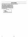
SETUP
MENU wrrH
AUXILIARY
VIDEO SOURCE
If one of the auxiliary video sources (VIDEO 1, VIDEO 2,
VIDEO 3, S-VIDEO 1 or S-VIDEO 2) is selected for your
main viewing picture, many of the SETUP MENU options
will not appear when the SETUP MENU is accessed. The
illustration below shows the SETUP MENU as it would appear. Only the CLOCK SET, CAPTIONS and CH. BACKGROUND options remain. Refer to the earlier discussions
when setting these options.
SETUP MENU
CLOCKSET
CAPTIONS
CH. BACKGROUND
Setup Menu for Video and S-Video Sources
2ss0
8-6
SELECTED
AUDIO MENU
AUDIO MENU
•_- BASS
TREBLE
BALANCE
AUDIO
SEQ
SURROUND
GENERAL
-
!
I
I
STEREO
ON
NOTE: All adjustments on the
AUDIO MENU are optional. You
do not have to use these features in
order to use your TV.
+
+
+
='_
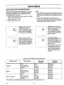
INFORMATION
Your TV is equipped to receive Multi-channel Television
Sound (MTS) when available in your area. It can also
receive a Second Audio Program (SAP), that is, a program
broadcast with two audio portions (two languages). The following modes of operation are available.
STEREO
NOTE: SURROUND
sound is only available if a stereo signal is being received and you have previously selected
STEREO using the AUDIO option or if STEREO is
selected by default.
The level of Surround sound varies relative to the Surround
information encoded into the program material. Some sources, especially if from a video tape, provide greater sensation of Surround Sound than may be obtained from a
standard TV broadcast.
Directs the sound to the left and right speakers as supplied
by the program source (broadcast TV station, VCR, etc.)
MONO (Monaural)
AUTOMATIC
Directs the same sound to both left and right speakers even
if the source being received is in stereo.
MODE
SELECTION
We recommend that you use the STEREO option. The TV
will switch automatically between the STEREO and
MONO modes dependent on the signal being received.
2ND AUDIO/SAP (Second Audio Program)
Directs the sound for the (SAP) Second Audio Program
(typically a second language) to both the left and right
speakers. SAP sound is always monaural.
SURROUND SOUND
If you prefer SAP, use the 2ND AUDIO/SAP
option. On
those stations which broadcast two audio portions, you will
hear the SAP (usually a second language). When the SAP
broadcast ends, the TV switches automatically between
STEREO and MONO modes. The TV switches back to
2ND AUDIO when the SAP broadcast resumes.
Surround sound gives the effect of surrounding you in
sound while listening to your TV. Surround speakers are
used with the rear-channel Surround sound provided by the
TV.
Surround sound is available in programs specially encoded
for the rear-channel sound track. Many broadcast television
programs, pre-recorded video tapes and video discs provide surround sound. Tapes and discs may provide a
greater sensation of Surround sound than obtained from a
TV broadcast.
BASS
Use ADJUST (ADJ) Left/Right to adjust the amount of
BASS (low-frequency level) in the sound. To decrease (-)
BASS, press ADJUST (ADJ) Left. To increase ( + ) BASS,
press ADJUST (ADJ) Right.
BALANCE
Use ADJUST (ADJ) Left/Right to shift the BALANCE of
sound between the left and right speakers as indicated by
the on-screen display. To increase the relative sound level
in the Left (L) speaker, press ADJUST (ADJ) Left. To increase the relative sound level in the Right (R) speaker,
press ADJUST (ADJ) Right.
TREBLE
Use ADJUST (ADJ) Left/Right to adjust the amount of
TREBLE (high-frequency level) in the sound. To decrease
(-) TREBLE, press ADJUST (ADJ) Left. To increase
( + ) TREBLE, press ADJUST (ADJ) Right.
zs8o
9 - 1
AUDIO MENU
AUDIO
SURROUND
Use ADJUST (ADJ) Left_ight to select the speaker audio
output mode. You may choose either STEREO, MONO or
2ND AUDIO/SAP. If current mode selection is not being
received, the status display shows NOT AVAILABLE.
If
STEREO is selected but not received, the following line appears at the bottom of the menu:
THIS PROGRAM IS NOT IN STEREO
Use ADJUST (ADJ) Left/Right to adjust the level of Surround sound you wish to obtain. To decrease (-) Surround
sound, press ADJUST (ADJ) Left. To increase (+) Surround sound, press ADJUST (ADJ) Right.
SURROUND sound is only available if a stereo signal is
being received and you have previously selected STEREO
using the AUDIO option or if STEREO is selected by
default.
If 2ND AUDIO/SAP is selected but not received, the following line appears at the bottom of the menu:
THIS PROGRAM HAS NO 2ND AUDIO
When SURROUND is activated, "SURROUND
SPEAKERS REQUIRED"
appears at the bottom of the
menu. This is a reminder that surround sound is only available when you have optional surround speakers connected
to the SURROUND SPEAKER jack. The TV's internal
speakers do not produce surround sound.
In either of these cases, the Channel/Time display will always show what type of AUDIO signal is being received
and has been selected default.
If you choose STEREO, you may want to enable Surround
sound by using the SURROUND option.
If no stereo signal is being received, the words NOT
AVAILABLE
appear next to SURROUND, and the following line appears at the bottom of the menu:
THIS PROGRAM IS NOT IN STEREO
NOTE: AUDIO mode selection is only available when one
of the ANT/CABLE
sources is selected for main picture
viewing.
SEQ (Spatial
If your AUDIO selection is either MONO or 2ND
AUDIO/SAP, the words NOT AVAILABLE appear next
to SURROUND and one of the following lines appear at
the bottom of the menu:
Equalization)
Use ADJUST (ADJ) Left/Right to turn SEQ ON or OFF.
SEQ improves tonal balance and increases apparent stereo
separation to produce a spacious and more natural sound.
Music and sounds appear to emanate from points outside
the television set, while dialogue is localized within the picture.
MONO HAS BEEN SELECTED
2ND AUDIO
NOTES:
.
SEQ is only available if a stereo signal is being received and
you have previously selected STEREO using the AUDIO
option or if STEREO is selected by default.
°
If no stereo signal is being received, the words NOT
AVAILABLE
appear next to SEQ, and the following line
appears at the bottom of the menu:
THIS PROGRAM IS NOT IN STEREO
If your AUDIO selection is either MONO or 2ND
AUDIO/SAP, the words NOT AVAILABLE
appear next
to SEQ and one of the following lines appear at the bottom
of the menu:
MONO HAS BEEN SELECTED
2ND AUDIO
HAS BEEN SELECTED
Some weak or nonstandard signals may not be suitable for
SEQ, which may make imperfections in the audio transmission more obvious. Turn SEQ off if this condition exists.
NOTE: If SEQ is available, you can turn SEQ ON or OFF
directly by pressing SEQ on the remote control.
25_o
HAS BEEN SELECTED
9 -2
Continuously
turns Surround
pressing
speakers
ADJ Left
OFF.
automatically
If the current program is not in stereo, you will not
be able to change the SURROUND
option. The
status display shows THIS PROGRAM
IS NOT IN
STEREO.
3.
If Surround
speakers
are not used, set SURROUND option to OFF for optimum stereo sound
reproduction.
4.
If you are in the SURROUND
menu option and
press MUTE on the remote control, only the Surround speakers are muted.
AUDIO MENU
AUDIO SELECTION
CONSIDERATIONS
NOTES:
The last line of the Channel/Time display shows the current
audio heard. The display is shown each time you turn the
"IV ON, change channels, or press ENTER. The audio
heard depends on the following:
• AUDIO mode selected on AUDIO MENU: STEREO,
MONO or 2ND AUDIO/SAP.
•
•
Audio signal being received.
Whether SEQ is ON or OFF.
CH 2
10:56
STEREO
STEREO selected using the
AUDIO option on the
AUDIO Menu and a stereo
signal is received; you will hear
stereo sound. The Channel/
Time display shows STEREO.
CH 2
10:56
MONO
MONO selected using the
AUDIO option on the AUDIO
Menu; you will hear monaural
sound regardless of the signal
actually received. The Channel/
Time display shows MONO.
•
Your AUDIO mode selection can override the type of
audio heard. For example, if you select MONO, you will
always hear monaural sound even if the signal received is
stereo.
•
If one of the auxiliary video sources (Video 112or
S-Video 1) is selected for the main picture source, the
Channel/Time display will not show an audio mode except
to show whether or not SEQ is turned on.
CH 2
10:56
SEQ
CH 2
10:56
SAP
STEREO selected using the
AUDIO option on the AUDIO
Menu, a stereo signal is
received and SEQ is turned
ON, you will hear SEQ stereo
sound. The Channel/Time display shows SEQ.
SAP selected using the
AUDIO option on the AUDIO
Menu and a SAP signal is
received; you will hear the SAP
audio. The Channel/Time display shows SAP.
If a SAP signal is not received,
the audio heard will be whatever is being received. The
Channel/Time display shows
what type of signal is being
received.
Audio Heard For Different
_,UDIO Selected
Audio Mode Options
Audio Heard,
SEQ OFF
Signal Received
Audio Heard,
SEQ ON
STEREO
Stereo
Stereo and SAP
Monaural and SAP
Monaural
Stereo
Stereo
Monaural
Monaural
SEQ Stereo
SEO Stereo
Monaural
Monaural
MONO
Stereo
Stereo and SAP
Monaural and SAP
Monaural
Monaural
Monaural
Monaural
Monaural
Monaural
Monaural
Monaural
Monaural
2ND AUDIO/SAP
Stereo
Stereo and SAP
Monaural and SAP
Monaural
Stereo
2nd Audio
2nd Audio
Monaural
SEQ Stereo
2nd Audio
2nd Audio
Monaural
* For VIDEO and S-VIDEO
_8o
Sources, the signal being received is assumed to be stereo.
9 -3
VIDEO MENU
VIDEO MENU
->.CONTRAST
BRIGHTNESS
COLOR
TINT
SHARPNESS
COLOR TEMP
VIDEO FILTER
AUTO FLESH
PICTURE PREF
GENERAL
INFORMATION
- _=
- _
- _zmm
G
- _
+
+
+
R
+
z
COOL
ON
OFF
CUSTOM
COLOR TEMP
CONTRAST
Allows you to change the "color temperature" or picture
white balance between cooler natural whites and warmer
(red) colors. To use COLOR TEMP, press ADJ until
either WARM or COOL shows in the display.
Adjusts the overall contrast and color level of the picture.
VIDEO FILTER
If the light areas in the picture are overly bright and some of
the highlight details are missing, press ADJUST (ADJ)
Left: until the highlights are restored.
The VIDEO FILTER reduces video "noise" or interference in dark picture areas while retaining detail and
sharpness in bright areas, resulting in overall clearer pietures.
All adjustments on the VIDEO MENU are optional. You
do not have to use these features in order to use your TV.
If the picture is grayish and lacks contrast and sparkle,
press ADJUST (ADJ) Right until you reach the CONTRAST level you prefer.
BRIGHTNESS
Adjusts the brightness level of black areas in the picture.
If the black areas are too light, press ADJUST (ADJ) Left
until yOUreach the BRIGHTNESS level you prefer.
If the black areas in the picture are too dark and show little
detail, press ADJUST (ADJ) Right until you reach the
BRIGHTNESS level you prefer.
COLOR
Adjusts the intensity of the colors in the picture.
If all the colors seem too vivid or intense, press ADJUST
(ADJ)
Left to decrease the COLOR intensity.
If all the colors seem faded or washed out, press ADJUST
(ADJ) Right to increase the COLOR intensity.
TINT
•
Select VIDEO FILTER
To turn the VIDEO FILTER ON, press ADJUST (ADJ)
until the word ON shows in the display. To turn the
VIDEO FILTER OFF, press ADJUST (ADJ) until OFF
shows in the display.
AUTO FLESH
Automatically maintains natural skin tones under changing
scene and video source conditions. To turn the AUTO
FLESH ON, press ADJUST (ADJ) until the word ON
shows in the display. To turn the AUTO FLESH OFF,
press ADJUST (ADJ) until OFF shows in the display.
PICTURE
PREF (Preference)
Lets you decide if you want to use your own CUSTOM
video settings, the factory PRESET video settings, or the
THEATER option.
Press ADJUST (ADJ) Left/Right to obtain the desired set-
tang.
Adjusts the color of the flesh tones.
If the flesh tones are too red or purple, press ADJUST
(ADJ) Left until you reach the desired flesh tones.
If the factory PRESET or THEATER setting is selected,
any adjustment made to the VIDEO Menu options from
this point, automatically changes the PICTURE PREF setting to CUSTOM, and saves your current video settings in
the CUSTOM mode.
If the flesh tones are green or have a greenish TINT, press
ADJUST (ADJ) Right until you reach the desired flesh
tones.
SHARPNESS
Adjusts the clarity for the clearest picture.
If the picture is too "grainy" and vertical edges show multiple lines on the right side, press ADJUST (ADJ) Left to obtain the desired SHARPNESS.
If the picture is too "soft" and vertical edges are fuzzy,
press ADJUST (ADJ) Right to increase the SHARPNESS.
25so
from the VIDEO Menu
10 - 1
PROGRAMMING THE REMOTE CONTROL
INTRODUCTION
Before using your new remote control,it must be programmed
to recognize the brands of equipment it will be used to
operate. If you are using a Zenith 'IV, Zenith VHS/VCR or a
Zenith cable-TV decoder, it has already been programmed for
you. Otherwise, follow the steps below.
2.
NOTE: The remote control can only be used to operate
one VCR, one TV and one cable-TV decoder at a time. If
you program the remote control to operate a TV that is not
a Zenith, it will no longer operate your Zenith TV.
4.
1.
3.
6.
For example, if you were programming
the remote
for use with a Zenith
TV, you would look up
"Zenith" in "Table 1.', and find code "101."
the brand
following
lines.
codes
Keep
for your equipment
this
operating
the proper brand code number determined
in
1.
LEARN. All three mode indicators
should
briefly, then turn off to indicate
the brand
has been programmed.
If all three mode indicators
error has occurred. Repeat
fail to light briefly, an
Steps 2-5 to try again.
7.
Repeat steps 2 - 5 to program the remote for the
other equipment you are using.
NOTE: CABLE mode can be programmed to operate a
second TV or second VCR, if desired.
on the
for fu-
guide
Enter
Step
Press
light
code
5.
Find the code that corresponds to each brand and
type of equipment
yon are going to operate. Refer
to Tables 1, 2 and 3.
Write
Press MODE repeatedly
to select the desired TV,
VCR or CABLE operating mode for the remote.
Press LEARN for about 5 seconds until the MODE
indicator
lights for the selected
TV, VCR or
CABLE mode of operation.
When batteries are removed: It will be necessary to
reprogram the proper VCR and cable-TV decoder codes.
ture reference.
TV CODE:
CABLE CODE:
VCR CODE:
Operating
f
Operating
Indicators
Mode
N
SELF..CT
0
QUIT
®®®
Numbered
CHANNEL
Buttons
Used to enter code number
for desired brand name
LEARN Button
__
C_D _--_---_
C_D
_C_D
CSD_
C_D_
_C_D
MBR3420
25s0
11 - 1
MODE Selector
PROGRAMMING THE REMOTE CONTROL
TV, VCR AND CABLE-TV
OPERATING
Table I. "IVCodes by Brand
'IV Brand
Name
Code
Admiral
Admiral
Akai
Amark
AOC
Bell & Howell
Centurion
Coronado
Curtis Mathes
Curtis Mathes
• Curtis Mathes
Daytton
Emerson
Emerson
Emerson
Emerson
Emerson
Emerson
Fisher
Fisher
General Electric
General Electric
General Electric
General Electric
Goldstar
Goldstar
Goldstar
Hitachi
Hitachi
Hitachi
JVC
JVC
J.C. Penney
J.C. Penney
J.C. Penney
J.C. Penney
J.C. Penney
KMC
KIN'
KTV
Lodge:net
Logik
LXI
LXI
Magoavox
•
Magoavo_
Magnavox
Magnavox
Magoavox
Magnavox
Majestic
Marantz
Marantz
Memorex
MGA/Mitsubishi
MGA/Mitsubishi
MGA/Mitsubishi
MGA]Mitsubishi
Montgomery Ward
MontgomeryWard
Montgomery Ward
Montgomery Ward
Montgomery Ward
2ss0
'IV Brand
Name
CODES
Table 3. Cable Decoder Codes by Brand
Table 2. VCR Codes by Brand
Code
116
121
104
103
104
121
119
103
116
119
121
119
103
104
123
124
131
136
109
118
106
107
114
116
103
104
119
102
103
129
125
132
MontgomeryWard
Montgomery Ward
MontgomeryWard
NEC
NEC
Pannsonic
Panasonic
Philco
Phiico
Philco
Philco
Philip*
Philip*
Pioneer
Portland
Quasar
Quasar
Realistic
Realistic
Realistic
RCA
RCA
RCA
Sampo
Samsung
Samsung
Samsung
Sanyo
Sanyo
Sanyo
Scott
Sears
119
121
130
104
119
106
107
103
104
112
113
112
113
135
103
106
107
105
123
124
104
116
126
119
103
119
134
108
109
118
119
103
104
110
114
117
119
103
103
104
121
121
133
137
103
112
113
119
127
128
121
104
120
121
104
119
120
130
103
104
105
113
114
Sears
Sears
Sears
Sears
Sears
Sears
Sharp
Sharp
Sharp
Sharp
Sharp
Sony
Sytvania
Sytvania
Sytvania
Sytvania
Sylvania
Sylvania
Tatung
Teknika
Teknika
Teknika
Teknika
Telerent
Telerent
Toshiba
Toshiba
Toshiba
Yorx
Zenith
108
109
110
111
118
134
103
105
122
133
137
115
112
113
117
119
127
128
106
103
112
121
124
103
121
110
111
134
119
101
VCR Brand
Name
VCR Brand
Name
Code
Code
Akai
223
Pentax
Audio Dynamics
Audio Dynamics
Broksonic
Canon
Citizen
Craig
Curtis Mathes
Curtis Mathes
DBX
DBX
Emerson
Emerson
Emerson
Emerson
Emerson
Ememon
F3sher
Fisher
Fisher
Funai
General Electric
General Electric
General Electric
Goldstar
Hitachi
Instant Replay
Instant Replay
JVC
202
218
221
214
209
212
214
216
202
218
203
221
223
226
233
235
211
212
213
231
214
216
220
209
215
214
227
202
Philco
214
Philip*
214
Philips
227
Pioneer
210
Pioneer
215
Pioneer Laser Disk 228
Quasar
214
RCA
215
RCA
216
RCA
220
RCA
227
Realistic
206
Realistic
208
Realistic
212
Realistic
214
Realistic
231
Samsung
220
Samsung
230
Sanyo
206
Sanyo
212
Scott
204
Scott
205
Scott
233
Sears
206
Sears
209
Sears
211
Sears
212
Sears
215
JVC
J.C Penney
J.C. Penney
J.C. Penney
Kenwood
Magnavox
Magnavox
Marantz
Marantz
Marta
Memorex
Memorex
Memorex
MGA/Mitsubishi
MGA/Mitsubishi
225
214
218
227
202
207
214
207
218
209
212
214
231
204
222
Sharp
Sony VHS
Sony Video 8
Sylvania
Sylvania
Sylvania
Symphonic
Tashiko
Tatung
Teac
Teac
Teknika
Toshiba
Toshiba
Vector Research
208
232
217
207
214
227
231
209
202
202
231
234
205
215
204
Montgomery Ward 208
Montgomery Ward 214
Montgomery Ward 219
NEC
202
NEC
218
Panasonic
214
Vector Research
Yamaha
Yamaha
Zenith VHS
Zenith VHS
Zenith VHS
218
202
218
201
225
229
11 -2
215
Cable Decoder
Brand Name Code
Drake Satellite
312
Drake Satellite
330
Gemini
305
Gemini
331
General Instrument305
General Instrument306
Cable Decoder
Brand Name Code
Pioneer
315
Regency
329
Saw.sung
335
Scientific Atlanta 316
Scientific Atlanta 323
Scientific Atlanta 336
Hamlin
Hamlin
Jerrold
Jerrold
Jerrold
Jerrold
Jerrold
Kale Vision
Macom
Macom
Macom Satellite
Magnavox
NSC
Oak
Oak
Panasonic
Panasonic
Paragon (Zenith)
Sprucer
(Panasonic)
Standard
Components
SIS Satellite
Telecaption 4000
Tocom
Tocom VII'
Toshiba
Toshiba Satellite
Zenith
Zenith
Zenith AV3000
Zenith Satellite
Zenith Satellite
Zenith Satellite
Zenith Laser Disk
302
303
304
307
308
309
310
335
314
321
322
334
335
311
332
313
320
333
313
335
324
325
317
318
322
319
301
322
327
312
330
328
326
MAINTENANCE
CARING
FOR
YOUR
AND TROUBLESHOOTING
TV
Your TV will look better, have a longer life and perform
better if you care for it properly.
A
safety, unplug the TV from the power outlet.
irst check to see that the TV is off. For added
Cabinet Care
Non-Wood Cabinet or Cabinet Components.
Moisten a soft cloth with a mild soap solution or Ivory dishwashing detergent. Wipe the surface with a damp cloth.
Then rinse the cloth in clean water and wipe the surface
gain. Allow the TV to air-dry before turning it on.
Picture Glass Cleaning
Wood Cabinets or Cabinet Components.
The picture tube face attracts dust particles and should be
cleaned regularly. To clean the face, spray a small amount
of glass cleaner on a cleaning cloth and wipe the picture
tube glass face until clean. Repeat if necessary.
Use any good furniture cleaner and polish. Regular care
will help preserve the finish.
To delay new dust accumulation, wet a soft cloth in
lukewarm water in which a little fabric softener or Ivory
dishwashing detergent has been mixed. Wring the cloth almost dry. Wipe the glass face. Make sure no drops of moisture are squeezed onto the glass. Do not wipe the glass dry.
Allow the glass to air-dry before you turn the TV on again.
EXTENDED
ABSENCE
Before an extended absence (such as a vacation) you may
want to unplug the power cord from the electrical wall outlet. This will protect the TV from possible damage from
lightning or power line surges. If you have an outdoor antenna, you may also want to disconnect the antenna lead-in
wires on the back of the "IV.
TV PICTURE
INTERFERENCE
Your TV picture may be affected by interference
one or a number of factors. These include:
Nearby Automobde
NOTE: If you unplug your TV, you will have to reset the
clock to the current time.
Ignition,
Electrical
Appliances,
caused by
etc.
Ghosts or Reflections Caused by signals being reflected
from surrounding buildings, water tanks, or other high structures.
Which causes a speckled, streaked picture. This is most
noticeable in weak signal areas.
Radio Signal Police, amateur or CB radio transmitters
cause interference.
Snow in Picture Caused by insufficient signal. Usually
caused by the TV being located too far from the TV station
or by an improper antenna installation.
These interference problems can often be corrected
through the use of a better antenna, signal amplifiers, or
various f'dter devices. See your TV dealer for additional information, and available TV accessories.
c_m
12 -- 1
may
MAINTENANCE
BEFORE
CALLING
FOR
AND TROUBLESHOOTING
SERVICE
Check these items and see if you can correct the trouble by
changing the adjustment of a control or the setting of a
switch.
By making these simple checks before calling for service,
you may save time and money.
Problem
Try This
Picture OK. Poor sound.
Re-orient antenna. Check for local interference. Try
another channel - possible station trouble? Check AUTO
FINE TUNE and TUNING BAND options in SETUP
Menu.
Sound OK. Poor picture.
Re-orient antenna. Adjust VIDEO Menu options with
PICTURE PREF in CUSTOM mode. Try another channel
- station trouble? Trouble with cable-TV system?
No picture or sound.
Is TV on? Is there power in wall outlet? Is "IV plugged in?
Is antenna hooked up? Is cable hooked up? Check with
your cable company. Cheek auxiliary audio/video
equipment. Check channel selection. Check TUNING
BAND and AUTO FINE TUNE option in SETUP Menu.
Picture blurred, ghost in picture, or distorted
Check antenna or cable hook up for broken wires? Possible
station trouble - try another channel. Check for local
interference.
No color, or poor color.
Check antenna or cable hook up. Adjust VIDEO menu
options with PICTURE PREF in the CUSTOM mode. Is it
a color program?
No sound.
Check VOLUME (VOL) setting. Check MUTE button
operation on remote control, if provided.
Cannot select certain channels.
Channels may be skipped in CH. ADD/DEL menu option.
Check TUNING BAND and AUTO FINE TUNE menu
option.
No picture or sound when Video Source is selected.
Is video component hooked up properly?. Are wires
connected to VIDEO 1/2 jacks on connection center?
Remote control does not work.
Are batteries okay? Is TV turned ON? Is TV plugged in? Is
remote in the TV mode?
No dosed
Are captions available? Is CAPTION 1 or CAPTION 2
selected using the CAPTIONS option on the setup menu?
captions.
Black box covers most of screen.
°
Is TEXT 1 or TEXT 2 selected using the CAPTIONS
option on the SETUP Menu? Text information may not be
available.
Always request that your technician use only genuine
Zenith exact replacement parts for continued Quality and
Safety performance. Keep your Zenith ALL Zenith.
NOTE: If your TV fails to respond to the PICTURE
PREF. selection, or to any other menu selection, you must
reset the TV. Simply disconnect it from AC power by unplugging the AC power cord from the power outlet. Wait a
few minutes, then plug the TV back into the power outlet.
You may have to set the clock to the proper time.
2580
12 -2
MAINTENANCE
VCR MODE CHART
1. OUTPUT
AND TROUBLESHOOTING
TO TV FROM ANTENNA
The operatingmode of yourVCR determineswhat type of
a program source is provided, andwhether the audio is
stereo or monaural.Use this flow chart to determine the
operating status of yourVCR, so that you can select the
proper viewing source and channel on your"IV.Select the
VCR outputchannel (3 or 4) on yourTV to view tapes or to
see programsselected by using the channel tuner in the
VCR.
START)
HERE
ANTENNA
OR CABLE-TV
INPUT TO VCR
VCR POWER
IS OFF
ALL
ANTENNA
OR CABLE-TV
CHANNELS
TO TV
STEREO
AUDIO
IF "IV IS
CAPABLE
During tape playback, we recommend you use the AUDIO
and VIDEO output jacks on your VCR for improved performance.
__
VCR POWER
_,,_ATUS
_--_
_VCR
POWER/;
IS ON
SWITCH IN VCR
POSITION
SWITCH IN TV
POSITION
t
ALL
ANTENNA
OR CABLE-TV
CHANNELS
TO "IV
STEREO
AUDIO
IF "IV IS
CAPABLE
NO
TV/VCR switch may be
marked W/VIDEO
on some VCR=.
YES
't
VCR TUNER
SELECTS
CHANNELS TO
BE SEEN ON "IV
VIDEO TAPE
PROVIDES
PROGRAM TO
BE SEEN ON TV
CHAN 3/4
CHAN 3/4
MONAURAL
AUDIO
ONLY
VCR ANTENNA
OUTPUT TO "IV
VCRMOD_I
OUT JACK ON VCR
12 -- 3
MONAURAL
AUDIO
ONLY
MAINTENANCE
VCR MODE
CHART
2. OUTPUT
AND TROUBLESHOOTING
TO TV FROM AUDIO/VIDEO
JACKS ON VCR
The operating mode of your VCR determines what type of
programsource is provided,andwhetherthe audio is stereo
or monaural Use this flow chart to determine the operating
status ofyourVCR, so thatyou knowwhen to select the VCR
(or au_liary) source on yourTV.
Use the LEFT and RIGHT AUDIO output jacks on the
VCR to get stereo sound. Select STEREO audio mode of
operation for the TV by using the options on the AUDIO
Menu of the TV. You must use the VIDEO output when
HERE
the LEFT
VCR POWER
IS OFF
and
RIGHT
AUDIO
outputs
are
VCR POWER
IS ON
NO OUTPUT IS
PROVIDED AT THE
AUDIO AND VIDEO
OUTPUT JACKS
@@@
VIDEO
OUT
J
R
L
AUDIO
NO
YES
OUT
Sta=_o VCR output to "IV
VCR TUNER
SELECTS
CHANNELS TO
BE SEEN ON YV
VIDEO TAPE
PROVIDES
PROGRAM TO
BE SEEN ON TV
1. TV channel or tape playback is provided at the video
output jack.
2. Stereo audio is provided at the audio output jacks if
stereo I1 present on the channel being received or on
the tape being played.
© ©©
VIDEO
OUT
t
R
L
AUDIO
OUT
Stereo VCR output to TV
VCP.MODO
12 -- 4
J
used.
PRODUCT REGISTRATION
CARD
You could win a full refund on your new Zenith product.
Product Card lost or misplaced?
Look for the Product Registration Card on your new video
product.
The Product Registration Card furnished with your video
product is pre-printed with its Model and Serial numbers.
Please fill out the card and mail it at your earliest convenience. It is imperative that Zenith know how to reach
you promptly if we discover a safety problem that would affect you. If the original card has been lost or misplaced, you
may use the replacement card provided below. Either card
will qualify you for the free drawing, but you are limited to
only one entry in the drawing. Complete the card, place it in
an envelope and mail it to:
Each month a drawing is held by Zenith from the completed Product Registration Cards received during the
preceding month. Zenith will reimburse the winner for the
full purchase price of the product purchased.
In order to participate, simply complete and return the
Product Registration Card at once, even if you choose not
to complete the information and interests portion of the
questionnaire.
Zenith Electronics Corporation
P. O. Box 173257
Denver, CO 80217-3257
Use the replacement Product Registration Card only if the
original card has been misplaced or lost.
The odds of winning the free drawing described above,
depend on the number of participants. Free drawing
offer is void in Canada and other places where
restricted or prohibited by law. Offer is void for
Hotel/Motel and Institutional models. Rental models
are not eligible.
PHOTOCOPY AND CUT ALONG DASHED LINE
Zenith
O
Please
Product
Print
,. I-l*.
Card
Registration
Clearly or Type
Q
=.1-1-,. 5.1-1=,. ,. I-1=-
Flrst Name
Initial
IIIllll
l llll
H5Z01-01
Area Code
Telephone
I I I IIII
I-II
II
Last Name
lllllllllllllllll
Street
Apt. No.
lililll
IIII
IIIIII
I I II
II I I I I I
City
illllll
_ate
I I I I I I I I I
Zip Code
Date
of Purchase
Day
IIIIIII!1
Illllll
Yr.
I
Please record the model number
and ser'_l number from _
sticker
on the back of your set.
Copy Numbers Here
From Label on Set
=llllllllll
®
Mo.
IIIIIllll-Illll
TVCARD2
I
I
RECOMMENDED
ACCESSORIES
FOR YOUR TELEVISION
MBC400P 3 FUNCTION
MULTI-BRAND REMOTE
CONTROL (2 Ibs)
Combining three remotes
into one has never been
easier. Operate your TV, VCR
and cable converter with one
remote control.
WALLMOUNTS
ff yourTV
(17 Ibe)
• Easy to install
screen is:
•
=rong
• 5 year warranty
• Made
inu.s
13"
• Spacesaving
19/20"
• Electronic mode switching
• Easy set-up: simply
depress the "team" key
for 5 seconds and enter
the three digit preprogrammed code
• Three LED mode indicators
• UL listed
. Adjustable tilt angle:
ONLY $29.95
Rus shipping
and handling
Order
this model
CWMO13 ONLY
(17 Ibs)
$69.95
CWM020
ONLY
(17 Ibs)
0 to 12degrees
25/27"
$89.95
CWM027
ONLY
(17Ibs)
$99.95
Plusshipping
and handling
• Operate on-screen menus
and displays
• Ideal replacement for lost
or broken remotes
ATS400 DELUXE 75
OHM INDOOR ANTENNA
(3 I_)
• 75 ohm all channel
UHF/VHF/FM antenna
ATSe00 OMNI-STAR
AMPUFIED UHF/VHF
ANTENNA (7 Ibs)
• Ornni directional amplified
UHF/VHF antenna
• Attic or roof mount
• High tech black styling
• Fully adjustable
telescoping VHF
elements
• Built-in amplifier boosts TV
signal strength up to 6
times on VHF and 9 times
on UHF
• Includes: 50 ft. and 6 ft.
coaxial cable with
connectors, U/V band
separator, mounting
bracket and hardware.
(Mast and mast mount are
not included.)
ONLY $129.95
ONLY $59.95
Plus shipping
and handling
Plus shipping
and handling
Order Form
• 14 position fine tuning
control
• Double isolated circuit
for added protection
• Rotating UHF fine
tuning element
• Rubber base feet
for added
protection and
stability
Photocopy Page and Detmtch Here
................................................................................,
To take adventage
of thb
excit_ag
oeer,pk_=e.nttout
thiscardandreturn,, photocopy
to:
Attn:Acce_ Offe_
Item Number
Price Per Item
Description
Zenith Video Tech Coq_lon
1900 NoAustin Avenue
Chicago, Illinois
60639
Char_ ca_ cu_on_ts,to _o_d
Sak_ Tax: Pkmse _d
your orde*', cait to_l free 1-800-255-S790
SublotaJ
your ttate tmkm tax If you
live In one of the following
Check i_l.yment method you prefen
stldeo.
Weight
State Sak_ Tax
CA 7 3/4%, GA 4%,/L 8 3/4%, KS 4.S%, KY 8%, ME _6,
rl
Check or money order
Ibs
PA 6%, RI 7%, TX 7 3/4%, VA 4 1/2%, WA 6 I/2%
{made payable to Zenith Video Tech)
Shipping Information
Total (Lb_)
Ship q_3 ht
Account
Number
1-51bs
IIIIIIIIIIIIIIIII
Exp. date
11 - 15 Ibs
$7.00
18 - 20 Ibs
$8.75
26 + Ibs
$10.45
PLEASE ALLOW 3-4 WEEKS FOR DELIVERY. THANK Y(TJ!
To receive Information on o(h_r firm _
products like those above,
please lake a moment to complete the following:
Television Model #
TVACCF_.S1
Tele_don
Serial #
Mo.
$4.50
$5.35
Signature
/
Total
Amount ofOrder
Charge
6 - 10 Ibs
Ship to:
Telephone
Name
Address
Apt*
City
State
Zlp Code
I
Day.
Yr.
Total Ship
NOTE: Price and avaJlebilitysubject to change.
YOUR ZENITH WARRANTY
Consumer Protection Plan for Zenith TV
Owner's Responsibility
Welcome into the Zenith family! We believe that you will be
pleased with your new Zenith Color TV. Please read this
Consumer Protection Plan carefully. It is a "LIMITED
WARRANTY" as defined under Federal Law. This warran-
Effective Warranty Date - Warranty begins on the date of
original consumer installation. For your convenience, keep
the dealers dated bill of sale or delivery ticket as evidence
of the purchase date.
ty gives you specific legal rights, and you may also have
other rights that vary from state to state within the U.S.A.
Zenith's Responsibility
Operating Guide - Read your Operating Guide carefully
so that you will understand the operation of your set and
how to adjust the customer controls.
Service Labor -- During a period of 90 days from effective
warranty date, Zenith will pay for service labor by a U.S. or
Canadian distributor-approved
Zenith service center when
needed as a result of manufacturing defects.
Carry-ln Service - Models under 19" diagonal (U.S.A.)
screen size must be taken to a distributor-approved
Zenith
service center for warranty service and must be picked up
by the owner.
Parts - New or remanufactured replacements for factorydefective parts will be supplied by a U.S. or Canadian
distributor-approved service center for one year from effective
warranty date (color picture tube - two years). Such replacement parts are warranted for the remaining portion of the
original warranty period.
Antenna - Reception problems caused by inadequate
home antennas or faulty antenna connections are the
owner's responsibility.
Home Service - Warranty service for 19" diagonal
(U.S.A.) or larger screen size models is provided in the
home.
Not Covered - This warranty covers manufacturing defects
and does not cover installation, adjustment of customer controls in the home, installation or repair of home antenna systems, cable converters or cable company-supplied
equipment; it also does not cover damage due to misuse,
abuse, negligence, acts of God or other causes beyond the
control of Zenith. Any alteration of the product after
manufacture voids this warranty in its entirety.
Important: Product Registration -- Please fdl out and mail
your Product Registration Card. It is imperative that Zenith
know how to reach you promptly if we should discover a
safety problem that could affect you.
Warranty Service - For warranty service information, contact your Zenith dealer preferably, or any distributorapproved Zenith service center. Parts and service labor that
are Zenith's responsibility (see above) will be provided
without charge. Other service is at the owner's expense. If
you have any problem in obtaining satisfactory warranty service, write:
Zenith Electronics Corporation
Customer Service Department
1900 N. Austin Avenue
Chicago, Illinois 60639-5079
Telephone: (312) 745-5152
Mon-Fri, 8:00 a.m. - 4:30 p.m. Central Time
NOTE: Before you ask for Warranty service, check
the Operating Guide section entitled, "MAINTENANCE AND TROUBLESHOOTING."
It may
be possible to avoid a service call.
_ARR3
ZENITH ELECTRONICS. CORPORATION
1000 MILWAUKEE
AVENUE
GLENVIEW, ILLINOIS 60025
Part No. 206-2580
Printed in U.S.A.
EP-EDCB