1
Feillu
rc,s
',,:'CR o,.;sP,_c_ramm_
with.
Ca:.:e Box Co,m.'o:
::rc"t A_:O"vlc_ec
•
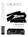
VRL4170
_acks
• M-:_3429
MJt:
•
-_r_J
Remote
,',,Jtoma:ic
mea_
C eaner
•
'_a:iabie
•
"vC -_ FiaSP.OacK
Siow Motior_
•
Message
Center
-",isp;ay
•
t Year. 8 £ver_t
•
irSt&-t
Casa,_:
• &:to
"[imer
.=,eco-.'!i.qg
:ty
C_a:'.ne
Search
• ,kJ:o Di_}ta'.
Picture
T;ackm_
• Center
Loac
Ta_.e
S,¢stem
• Quick
• A;':c
Start
Loadin_
_'iayback
St/stem
• Auto COu,'=ter Reset
•
Ca,:_ter
•
!_:Jex Search
• H_
Memory
System
S_rCuitry
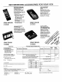
Video Cassette Recorder
Operating
Guide and 'Warranty
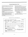
Return your Product
RegL_tration Card
and your VCR could
be Free'.,
A
WARNING:
TO REDUCE
THE RISK OF ELECTRIC
REMOVE COVER
PARTS
INSIDE.
PERSONNEL.
SHOCK DO NOT
(OR BACK). NO USER SERVICEAE;LE
REFER
TO QUALIFIED
SERVICE
TO PREVENT
FIRE OR SHOCK HAZARDS,
DO
EXPOSE THIS PRODUCT TO RAIN OR MOISTURE.
A
NOT
The lightning flash with arrowhead symbol, within an equilateral
triangle, is intended to alert the user to the presence of uninsul_tted
"dangerous voltage" within the product's enclosure that may be of
sufficient magnitude to constitute a risk of electric shc_: to
persons.
A
Safety
The exclamation
point within an equilateral triangle is intende,:l to
alert the user to the presence of important
maintenance
(servicing)
instructions
in
accompanying the appliance.
Tips
REGULATORY
Refer to the "Safety Tips" booklet that came with your
product for important safety considerations.
generates, uses and can radiate radio frequency, energy
and, if not installed and used in accordanct: with the in-
provides guidelines for proper grounding and, in partitular, specifies that the cable ground shall be conneeted to the grounding system of the building, as dose
to the point of the cable entry as practical.
structious, may cause harmful interference to radio communicatious. However, there is no guarantee that
interference will not occur in a particular ktstallation. If
this equipment does cause harmful interference, to radio
Power-Cord Polarization
This product is equipped with a polarized alternatingcurrent line plug (a plug having one blade wider than the
other.) This plug will fit into the power outlet only one
way. This is a safety feature. If you are unable to insert
the plug fully into the outlet, try reversing the plug. If the
plug should still fail to fit, contact your electrician to
replace your obsolete outlet. Do not defeat the safety
plug by altering it in any way.
or television :reception, whiich can be detertained by turnhag the equipment off and on, the user is encouraged to
try to correct the interference
lowing measures:
TO PRI_VENT ELECTRIC SHOCK, MATCH WIDE
BLADE OF PLUG TO WIDE SLOT, FULLY INSERT.
ATTENTION
POUR _VITER LES CHOCS ]_.LECTRIQUES, INTRODUIRE
LA LAME LA PLUS LARGE DE LA
FICHE D,MqS LA BORNE CORRESPONDANTE
DE
ET POUSSER
JUSQU'AU
f_....Z'--L*
Reorient
or relocate the receiving antenna.
•
Increase the separation
and receiver.
•
Connect the equipment into an oufltet on a circuit
different from that to which the receiver is
connected.
•
Consult the dealer or an experienced
technidan for help.
"P._.%lL
_'1^--*----:--
between
the equipment
radio/TV
CAUTION: Do not attempt to modify this product in any
way without written anthorizzttion from Zenith
Electronics Corporation. Un:mthorized modification
could void the user's authority to operate rids product.
FOND.
€'_
by one or more of the fol-
•
CAUTION
LA PRISE
INFOFIMATION
This equipment has been tested and found to comply
with the limits for a Class B d_gital device, pursuant to
Part 15 of the FCC Rules. These limits are designed to
provide reasonable protection against harnfftd interference in a residential inslatLation. This equipment
Note to Cable TV System
Installer
This reminder is provided to call the cable 'IV system
installer's attention to Article 820-40 of the NEC that
purpose of the polarized
operating and
the
lkerature
t-_ .....
"_
4_
I
General Information
Introduction
Zenith Electronics Corporation
Customer Service Department
1900 N. Austin Avenue
Welcome into the family of Zenith Video Recorder owners.
Tlfis guide provides instructions on how to operate your
new VCR. It is supplemented by a booklet containing
Safety Tips. We urge you to read these publications carefully so that you will receive full enjoyment from your new
Zenith VCR for many years to come.
Chicago, Illinois 60639-5079
Telephone: (3E_) 745-5152
Mon-Fri, 8:00 a.m. - 4:30 p.m. Central Time
Your new Zenith vCR has been designed and built to give
you the very be,st in quality, features and performance. There
are approximately 75 regional Zenith distributors and
thousands of distributor-approved Zenith video recorder service centers throughout the U.S. and Canada who can attend
promptly and effectively to ordinary service needs.
Send the model number, serial number, and date of purchase or original installation, with a full explanation of the
problem and the service history. We will welcx3me the opportunity to look into your spedfic question or problem and
to be of assistance in resolving it promptly.
The model and[ serial numbers of your new VCR are located on the VCR cabinet. For your future exmvenience and
protection, we suggest that you record these numbers here:
If you should _tve an unusual performance or service problem
that cannot be ,,_atksfactorilyresolved by your distn'butorapproved Zenith video recorder service center, contact the
regional Zenith distributor in your area, or write or call:
Model No.
Serial No.
Installation
Considerations
Before you install your VCR...
Ventilation
_k
•
Keep the video recorder
strong magnetic fields.
•
Use only Zenith approved and recommended accx_sory units with your Zenith video recorder to avoid
potential hazards.
•
Save the stripping carton mad packing material. They
will come in handy if you emr have to ship your video
recorder. For maximum protection, re-pack the video
recorder as it was originally shipped front the factory.
forations in the back and bottom of the cabinet.
VCR running cool. Air circulates through perDo not block these vents or you will shorten the
life of your VCR.
- Your VCR is designed to
60perate
Hertz on
AC.normal
Do not
attempt to
operate120it on
household
current,
volt
DC current.
Power Cord -- Your VCR power cord has a
polarized plug as required by Underwriters'
_
Plugging in Your VCR -- Be sure to plug ]tourVCR into
an "unswitched" AC power source. The "switched" AC
outlets found on some video equipment will notcontinue
supplying power to the VC'R oncethe equi,pment ks
turned off. If the power to the VCR ks interrupted for an
extended time, you will have to reset the ckw.k in the VCR.
- Proper ventilation keeps your
Power Source
_
•
aboratories. It has one regular blade and one
wide blade and fits only one way into a standard
electrical outlet. If the blades will not enter
either way, your outlet ks very old and non-standard. A new outlet should be installed by a qualified
electrician.
Safe Operation
Moisture condensation
conditions:
is apt to occur under the following
•
When the video recorder is moved from a cold place to
a warm place.
•
Under extremely humid conditions.
- Your VCR is manufactured
unusual stress caused by dropping or mishanand tested with your safety in mind. However,
dliug, exposure to flood, t'a'e, rain or moisture,
or accidental spilling of liquids into the VCR,
can result in tx)tential electrical shock or fire hazards. If this
happens, have your VCR checked by a service technidan
before using it again.
and video cassette away from
In locations where moisture condensation
Please read and observe each safety point in the "Safety
Tips" folder when installing and using your VCR.
i
may occur:
•
Keep the power cord phtgged into an AC outlet and
the POWER switch set to ON. This will help prevent
condensation from oc.curri.ag.
•
When condensation has occurred, it will not evaporate
quickly once the power is switched on. Wait a few
hours for the video recorder to become dry before
using the video recorder.
VCRINTR4
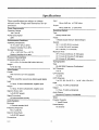
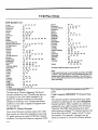
Specifications
Input
These specifications
are subject to change
without notice. Weight and dimensions
are approximate.
Minus 8 dB into _>47,000 ohms
Output
Minus 8 dB into _<1,000 ohms
Power Requirements
Recording
Operating Voltage
Type
120 V, 60 Hz
Rotary Helical Scan
Power Consumption
Heads
30W
Environmental
4 Heads Double AzimLr:h (Slant Design)
Conditions
Speeds
Operating Temperature
SP- 1 5/16 IPS (33.34 mm/sec)
41 ° F to 95° F (5°C to 35°C)
LP- 21/32 IPS (16.67 mm/sec)
Relative Humidity 5% to 80%
EP- 7/16 IPS (11.12 mm/sec
Maximum Time
Storage Temperature
-4 ° to + 140 ° (-20° C to + 60 ° C)
SP- 2 Hours 40 Minute_ 0"-160 tapes)
Relative Humidity 5% to 80%
LP- 5 hours 20 minutes (T-160 tapes},
Physical Characteristics
EP- 8 hours (T-160 tapes)
Dimensions (W x H x D)
Tuning
14.2 x 3.5 x 13.4 Inches (360 x 88 x 340 mm)
System
Type
Weight
50--800 MHz Frequenc!/Synthesized
VHF Channels
12 Ibs (5.5 kg)
Video System
Format
2to 13
UHF Channels
VHS 1/2 inch (12.7 mm) Cassette
14 to 69
Signal
CATV Channels
NTSC color/EIA monochrome (525 lines/60 fields)
lto125
Input
(4A, AtoW,
W + 1toW
Input
1.0 Vp-p, 75 ohms unbalanced, negative sync
1.0 Vp-p, 75 ohms unb_danced
Output
Output
1.0 Vp-p, 75 ohms unbalanced, negative sync
1.0 Vp-p,, 75 ohms unb_Llanced
Signal to Noise ratio
Audio Signals
___43dB (SP speed)
Monaural (Frequency' IVlodualted)
Signal Processing
Timer
HQ enhancement circuitry
Program Capacity
Audio Systems
1 Year/8 Events
Monaural
Power Backup
1 Channel standard VHS
10 seconds
Frequency Response
70 to 10,000 Hz
Signal to Noise Ratio
_>40dB (SP speed)
Connections
261._0
System
ii
+IM, A-5toA-1)
Table of Contents
Note: This is a task oriented operating guide and is broken down into the steps one would ordinarily follow in using this VCR; VCR/Remote controls, Installation, VCR Setup, Playing Tapes, Recording Tapes, etc.
Safety Warnings
5 VCR Setup
8 Instant Timer Recording
Regulator?," Information
..................
Inside front Cover
Electrical Shock Warnings
..................
Inside front Cover
Enter information that prepares your
VCR to receive programs that are
broadcast in your local area and
specifying VHFAJHF type
antenna(s) or Cable service
(CATV) ......................
5-1
On-Screen Menu System ..........
5-1
Setting the Clock ................
5-2
Receiving TV Programs VHFFLIHF or
Cable TV Service .............
5-2
Channel Search .................
5-2
Channel Save/Skip ...............
5-2
VCR Function On-Screen Display 5-3
Power Failures .............
5-3, 13-1.
Error Messages .................
5-3
VCR Message Center Displays 54,5,6
Instru,_ ans for recording what you are
currrently viewing on your "IV .... 8-1
General Information
Introduction ......................
Installation Considerations
.........
i
i
Specifications
VCR Specifications
Listing ........
ii
1 VCR Front Panel
,Controls Description
and Use .....
1-1
2 VCR Back Panel
,Connections Description and Use
Audio/Video Connection Jacks...
,Antenna Connection Jacks .......
Channel 3-4 Switch ..............
2-1
2-1
2-1
2-1
:3VCR Remote Control
Controls Description and Use .....
Installing Batteries ...............
Multi-brand Codes ...............
3-1
3-2
3-3
4 VCR Installation
Unpack the VCR and Accessories 4-1
System Connections
]Basic First Time Connections VCR,
Antenna, Cable Box and "IV Set 4-1
Replacing an old VCR with a Zenith
VCR ........................
4-1
New VCR Owner Connections .... 4-1
VCR Front and Back Panel
Connection Options ...........
4-2
Cable (CATV) Connections ......
4-3
System Diagram .................
4-3
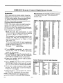
Ilndex of Features
1 Year, 8 Event Timer ...........
:181 Channel Capability ...........
Auto Channel Search ............
Auto Counter Reset .............
9-1
ii
5-1
6-2
Auto Digital Picture Tracking .....
Auto Playback System ...........
6-2
6-1
:'.613-O
6 Playback
(Playing Tapes)
Playing Tapes ...................
Stop Playing Tapes ..............
Loading and Ejecting Tapes ......
Additional Playback Features .....
Still/Slow Motion/Pause ..........
Rewind/Fast Forward ............
Reverse/Forward Search .........
Tracking Adjustment Auto/Manual
Real Time Tape Counter .... 6-2,
Index Search (See Section 12)
Automatic Counter Resetting 6-2,
Elapsed Time Display .......
6-2,
Counter Memory ...........
6-2,
7 Recording
6-1
6-1
6-1
6-2
6-2
6-2
6-2
6-2
1.2-1
Instructions for recording TV
programs while you are away ...9-1
10 VCR Plus Recording
Recording with VCR Pluscodes
11 VCR Plus Recording
VCR Plus Setup ........
11-1, 2, 3, 4, 5
12 Aclditional
Operations
Recording Speed Selection, Real
Time Tape Counter, Automatic
Counter Reset, Counter Memory,
Index Search, Blank Search,
Doul_le Speed Playback, VCR
Flashback ................
12-1, 2, 3
13 Service
Information
(VCR Operating Difficulties)
Before Calling for Sen,ice .......
13-1
Problem/Resolution Chart ..... 13-1, 2
Maintenance ..................
13-2
1.2-1
12-1
1.2-1
7-1
7-2
...............................
Center Load Tape System ........
1-1
Counter Memory ...........
6-2, 12-2
HQ Circuitry ....................
il
Index Search System ............
12-2
Instant Recording ...............
8-1
LED Display ...............
1-1, 3-1
New Larger Controls ............
1-1
14-1
15 Product Registration
Card
Receive Current Product Info ....
16 Your Zenith
...............................
°o°
Ill
10-1, 2
14 Ac:cessories
Tapes
Recording ......................
Additional Recording
Features .....................
9 Timer Recording
15-1
Warranty
16-1
On-Screen Programming .........
5-1
Slow Motion ....................
6-2
MBR3429 Multi-Brand
TV/VCR/Cable Box Remote
Control .....
3-1, 6-1, 7-1, 8-1, 9-1
VCR Plus ......
10-1,, 2, 1.1-1,2, 3, 4, 5
I
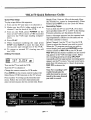
VCR Front
Q)
Panel
Controls
b
Qb
Qb
Q.
,]
L#_
RE_'
C
.lt.I.
IF
t,.,:
t_SPEED SEARCH--J
_,
PAUSE
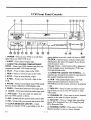
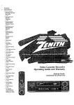
1. POWER -- Press to turn VCR on or off. Red
light will be on while VCR is on.
2. EJECT - Press once to eject tape.
3, CASSETTE LOADING COMPARTMENT
DOOR -- Insert your VHS cassette tape into the
compartment until VCR loads the tape.
4. PLAY -- Press to play a tape in the VCR.
5, REW -- Press to rewind a tape in the VCR.
6. STOP -- Press to stop playing a tape.
7. F FWD -- Press to fast forward a tape in the
VCR.
8. PAUSE -Press to momentarily cease VCR recording or to obtain a still picture while playing a tape.
9. VIDEO - Front panel alternate video input jack.
10. AUDIO - Front panel alternate audio input jack.
11. VHS Logo - You must only use tapes that
have the VHS symbol on them.
12. AM - Symbol tells you current time is set at AM.
13. PM - Symbol tells you current time is set at PM.
14. CLOCK]MESSAGE
CENTER -- Clock
remains on whether VCR is operating or not. If a
z,x:_o
power failure occurs the clock will reset to SET
CLOCK.
power failure will also erase some
information; the same will happen if you disconnect the power cord.
Message Center - Info:rmation will be displayed
in the message center detailing the VCR's current operational mode.
15. CASSETTE LOADED VCR SYMBOL-- A
cassette tape is loaded _md ready for operation in
the cassette loading corapartment.
A
16. VCR - This symbol lights when the VCR
mode has been selected! by means of the
TV/VCR key on the remote control or bYplaying
a tape.
17. REC ITR -- Press to make an instant recording of what you see on your "IV screen or other
video input.
18. CHANNEL UP -- Pre:;s once to n_tovechannel
number to the next set higher channel.
19. SP/LP/EP -Press to change tape recording
speed. SP is Standard Play, LP is Long Play and
EP is Extended Play.
20. CHANNEL DOWN -- Press once to move
channel number to next set lower channel.
1- 1
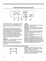
VCR Back Panel Connection Jacks
CH4
__.JCH3
2. Video
The OUT jacks will be used to send the VCR signals out to other sources. The IN jacks will be
used to bring signals into the VCR. (See Installation.)
VIDEO OUT- Connec,_ion jack for sending
VCR signal to another source.
VIDEO IN -- Connection jack that receives the
video signal from a video camera, camcorder
or
other source.
Use these jacks for improving the audio and
video signal performance
of the VCR by, for example, connecting
the VCR to a stereo system or
to the input jacks on a stereo TV. They are also
used to connect other units such as a video
camera" camcorder,
Stereo Hi-Fi or another
3. ANT OUT - Connect hookup cable supplied
with this VCR from this jack to Antenna In on
your TV set or other u_Lit,
4. ANT IN - Connect your existing
CATV cable to this jade.
VCR for dubbing purposes. These other sources
are accessed by changing the VCR source to
AUX mode. (See Section 5 VCR Setup.)
AUDIO OUTConnection jack used to send the
VCR audio signal to other sources
AUDIO IN - Connection jack that receives the
audio signal of a video camera, camcorder or
other source.
Audio]Video
Connection
jack that receives
corder, camcorder
VIDEO
i
jack that receives
corder, camcorder
2- 1
front audio connection
the audio signal of a video reor other source.
7. VIDEO -- Alternate
f
2_,_o
or
Jacks
6. AUDIO -. Alternate
))_ AI.IDIO
antenna
5. Oh 3-4 - VCR output channel switch. Set this
switch to send the VCR sigaal to your'IV set. Use
channel 3; if3 does not work use channel 4. The TV
will receive the signal from your VCR over this channel Your TV set's channel and this VC'R switch must
both be set to the same n_aber; either 3 or 4.
1..Audio
VCR Front Panel Alternate
the
from video connection
the video signal of a video reor other source.
.€
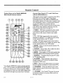
Remote Control
Operate Other Brand of TVs and Cable Boxes
with the MBR3429Remote
Control Keys on the Zenith MBR3429
Multi-Brand
Remote Control
This remote can be taugl_t to operate other InfraRed (IR) controlled
TVs and Cable Boxes.
Switching between "IV, VCR and CABLE with
the remote control, will allow you to operate each
unit individually.
Some oi[ the advanced features
on your TV cannot be accessed with the
MBR3429. Use the remote control provided with
YOUr TV for these advanced features. See the
multi-brand
codes listed on page 3-3.
1. CABLE --. Will light momentarily
when mode
is switched to operate cable box or when you
press a key on the remote while in the Cable
mode.
go-
2. TV - Will light momentarily when. mode is
switched to operate TV or when you press a key
on the remote while in the TV mode.
OOO
3. VCR - Will light momentarily
when mode is
switched to operate VCR or when you press a key
on the remote while in the VCR mode.
4. MODE - Press to switch control between TV,
VCR and CABLE.
5. OFF/ON - Turns VCF:, TV or cable box off or
on when in that particu]tar mode.
iI, +
6. MENU - Press (while in VCR mode.) to place the
VCR Main Menu (VCR Features) on the TV screen.
7. SOURCE - A function key for your TV, refer
to TV operating guide.
8. FLASHBK - When playing a tape, press to
change image on TV screen to program being
received by VCR tuner.
9. QUIT -- Press to exit main menus or to access
Closed Captions available on some Zenith TVs.
Your Zenith MBR3429 remote control operates
your VCR by means of an Infra-Red
(IR) Signal.
It must be aimed at the VCR to function. While
10. CHANNEL -- Press Up arrow to l;o to next
higher channel, press Down arrow to go to next
lower channel.
controlling
the VCR, the VCR LED (Light Emitting Diode) will light each time a key is pressed.
2,613-0
11. VOLUME -- For Zenith TVs press Up arrow
to increase volume level, press Down arrow to
decrease volume.
3- 1
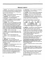
Remote Control
12. MUTE - For a Zenith TV or other brand you
have programmed
the remote to operate, press to
turn the sound coming from your TV off, press
again to restore the sound.
26. VCR PLUS -- Press to display the VCR Plus
Code information on the :IV screen.
13. SEQ -- Some Zenith
28. ENTER - Press to set entered
that will be operated
14. SEARCH
recorded
TVs have audio circuits
with this key.
-- Use to advance
tape to an indexed
or rewind
information.
29. Numbers
0 through 9-- Use the,;e keys to
choose information where applicable. These keys
are also used[ for direct channel access.
a
position.
15. TV/VCR -- A change key. Press to change
tween TV and VCR tuners to show broadcast
programs
27. CH MAP - Press to begin Channel Mapping
procedure
or to review Channel Mapped data.
be-
Remote Control Battery Compartment
on the TV screen.
16. TIMER - Press when all program recording
information
has been entered. This will turn off
the VCR until the program time arrives. (After
the program has been recorded, press again to
release VCR from Timer Mode.) Note: Once the
VCR is in the Timer Mode the TIMER key must
be pressed to release the VCR from Timer Mode.
17. F FWD--
Press to advance
2.
30. SELECT - Use this key to choose information
in the menus and rob-menus, where required.
31. ADd - Press to choose.information
where applicable; also used to manually adjust the tracking.
tape.
18. PAUSE - Press to momentarily
cease VCR
record functions or to obtain a still picture while
playing a tape.
1. Open battery compartment
on the back of the
remote control by using your fingernail to
squeeze the tab lock open.
19. PLAY - Press to begin playing a tape.
20. STOP -. Press to stop playing or recording
tape.
2. Lift compartment
a
Install two (2) high quality new alkaline AAA
size batteries in the VCR remote control.
21. REW -- Press to rewind tape.
2:2. RECORD
Note the positive and negative positions for placing the batteries in the remote control. Once
fresh batteries are installod into the remote con-
-- Press and hold down until
REC CH and the channel number you are recording appear in the VCR message center to start
recording on a tape.
2!3. MEMORY -- Use with the tape counter
cess locations on recorded tapes.
24. AM/PM
- Use to enter
AM or PM where
door out and install batteries.
trol it is ready for use.
3. Replace
to ac-
compartment
control.
Notes:
Be careful not to place heavy objects on top of
the remote control button_;. Prolonged[ accidental
operation of the remote control will shorten battery life.
re-
quire&
2!5. LEARN - Other product's codes can be
learned by this remote control; use the numbered
buttons and this key to enter the information
necessary to program the MBR3429 remote to
operate your cable box and TV set.
If you do not use the remote control for a month
or more, remove the batteries. Batter)' leakage
can cause damage to the remote control.
Zenith is not responsible',
such battery leakage.
2613-O
door on remote
3-2
for damage
caused by
MBR3429 Remote Control Multi-Brand
Codes
Introduction
When batteries
are rereoved:
Before using your new remote control, it must be
programmed to recognize the brands of equipment
it will be used to operate. If you are using a Zenith
TV, Zenith VHS/VCR or a Zenith cable-TV
decoder, it has already been programmed for you.
Otherwise, follow the steps below.
to reprogram the proper
decoder codes.
Table 1 Remote
It will[ be necessary
VCR and cable-TV
Control "iV Codes
by Brand
Admiral
116
Mag navox
112
Satn_Jng
13,4
Ad mira/
121
Magnavczx
113
Slmyo
108
AkaJ
Ama_
AOC
104
I O3
104
Magnavc_x
Magnavox
M,agmz_x
119
127
128
,Slmyo
S=myo
,_',otl
109
118
119
Bell & _11
Cerdudon
121
119
103
MaStic
k4atantz
Marantz
121
104
120
S4_rs
$4_r$
Sa_
103
108
10_
Curtes M_hes
Curtis Ma_hes
116
119
Mernore)_
MGA,/Mit:;ub shi
121
104
$4_._
Seqars
110
111
Curtis Mat hes
121
MGA/Mitsul> shi
119
Se_u_
118
Da_on
Emerson
119
103
MGA,,'M_,.ua_ shi
MGA/M_;ub_shi
120
130
S4_,rs
S_p
134
103
Emerson
Emerson
104
123
Mordgomery
Montgorrmry
W_u'd 103
Ward 104
Sh_np
Sharp
105
122
Emerson
ErnemJoct
124
131
Mo_gorr_
Montgomery
Ward 105
W_u'd 113
Sharp
Sharp
133
137
E_
136
Montgo_ery
Ward
114
Sony
115
Fisher
109
MontgomePJ
Ward
119
_ytvzu',a
112
For example, if you were programming
the
remote
for use with a Zenith
TV, you
would look up "Zenith"
in "Table 1.", and
find code "101."
Fisher
GenemJ Electric
_
E,kN:_
Genera/Elect_
118
106
107
i 14
Montgon'_)/Ward
_Ig_H'j
Ward
121
130
NEC
104
Syivzu'da
Syk,_zx_z
S_h_'da
S_h_nia
113
117
119
127
Gene_
116
103
104
119
NEC
Panasonic
P_msonic
Phil¢o
119
106
107
103
Sy_,'da
Tadur',g
Tek_ika
Tei_ika
128
106
103
112
Write
codes for your equipment
Hitachi
Hitachi
102
103
Phit¢o
Philo:>
104
113
Te_o'dka
TeJ0nika
121
124
on the following
guide for future
lines. Keep
reference.
Hitachi
JVC
JVC
129
125
132
Philips
Philips
Pioneer
112
113
135
Te_rd
Telerent
Tc_',hib_
103
121
110
TV CODE:
CABLE CODE:
d.C. Penney
d.C. Pent'my
'tim
'110
Podland
Qua.saz
103
106
Toshib_
To_;hiba
111
134
d.C. _
!114
Oua.s_
107
YO_X
119
J.C. Pelf'my
KMC
_ 19
_03
ReaJistk:
Re4dist_c
105
123
Zenith
101
I<TV
1103
FleaJistic
124
K'W
Lo<_jenet
1:04
121
RCA
RCA
104
116
Logik
121
RCA
126
LXI
133
Sampo
119
LXJ
137
Samsung
103
Max:jrt4z_x
103
Sams_ng
119
NOTE: This remote control can only be used to
operate one VCR, one TV and one cable-TV
decoder at a time. If you program the remote control to operate a TV that is not a Zenith, it will no
longer operate your Zenith TV.
1. Find the code that corresponds
to each
brand and type of equipment
you are going
to operate. Refer to Tables 1, and 2.
the brand
this operating
2. Press
MODE repeatedly
to select
the
desired
TV, VCR or CABLE operating
mode for the remote.
3. Press
LEARN
for about
5 seconds
until
the
Electric
MODE'.
indicator
lights
for the selected
TV, VCR or CABLE
mode of operation.
4. Enter
the proper
determined
in Step
5. Press
LEARN.
All
should
light briefly,
cate the brand code
brand
code
number
1.
three
mode indicators
then turn off to indihas been programmed.
,6. If all tlhree mode indicators
fail
briefly,
an error
has occurred.
Steps 2-5 to try again.
to light
Repeat
'7. Repeat
Steps 2 - 5 to program
the remote
for the other equipment
you are using.
Table 2 Remote Control Cable Decoder
Codes by Brand
Dra_e Satellite
Dr_e S_ellite
312
330
Macom
Ma¢om
Gemini
305
_
Gemini
GeneraJ Instrument
3,31
305
)4_gnavox
NSC
334
335
_l'€_; ,S_te|lite
Tek_.aption 4000
324
325
General In_rument
Hamlin
306
3t3_
Oak
Oak
311
332
Tocom
To€ore VlP
317
318
Ha_[_n
Jerro4d
303
304
Parm.sonic
P_
313
320
To_hib_
To_l'db_ Salellite
322
319
Jerrold
3eno_
307
308
Pm_Kjon (Zenith)
Pioneer
333
315
Zen_lh
Zenith
301
322
Jen'old
3(;_
Regency
3_9
Zenith
AV3000
327
Jerroid
Kale V_on
Cable Deco<_r
310
3;_
Samsur_
SoentE_c Atlanta
Scientific A_tm
335
316
323
Zenith
Zenith
Zenith
S_ellite
SaXellite
Sa.teJlite
312
330
328
Cc_e
Scierdific A,tlZ_lta
336
Zenith
La.ser Disk
326
NOTE: CABLE mode can be programmed
to
operate a second TV or second VCR, if desired.
_3-o
Brand Name
314
321
S4flell,te
Sprucer
3- 3
322
_ic)
Ste.ndatd
313
Components
Installation
Unpack The VCR
and All Accessories
Disconnect
antenna from your
TV or other units. Position
VCR in desired location, away
from any interfering wiring.
Turn the VCR around so you
are looking at the back side and
locate the connections
panel.
Note: It is important to place
the VCR where you plan on
using it. After setting the Clock
;and completing the Channel
Search, if you disconnect the
VCR power cord some of that
iinformation will be erased.
O'his will also occur if there is
a power failure.)
Antenna
Diagram
A is designed
you connect
your VCR
antenna
and TV set.
Step
to help
Step
to your
Connect the hookup cable supplied with your VCR to the
VCR ANT OUT jack. Connect
the other end to the ANT IN
1.
Connect your antenna cable to
your VCR using the VCR ANT
IN jack located on the back
panel of the VCR as shown. (If
this is not how your antenna
cable looks you may need additional adapters to complete
these connections.
Refer to
page 4-2 for connecting
VCR).
Diagram
your
;!.
jack on the TV set.
Step
3.
Slide: the CH3-4
in the CH 3 position; this sends
the VCR signal to the TV set
over channel 3. (If CH 3 does
not work slide the switch to
CH 4.)
A. VCR Back Panel Cable
Connections
Hookup Cable
Connections
Connect the antenna to the
VCR and the VCR to the TV.
]{fyou have CATV (Cable TV)
use the connections
detailed on
Step 2 Hookup
Cable
page 4-3.
Notes:
If you are replacing an existing VCR, disconnect your
old VCR and connect the
'D----_CH4
CH 3
new VCR in the same way.
If this is your first VCR installation refer to Connections 4-2 for hookup
procedures.
For basic first-time connections, proceed as shown in
Diagram A.
,,>luo
switch so it is
Step 1 From
Cable/Decoder Box or
CA-TV Antenna (No
Decoder Box)
4 -- 1
Step 3 CH3-4
Switch
Connections
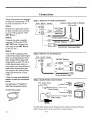
These illustrations
are designed
to help you connect your VCR
to your antenna and TV set.
Step 1.
Step 1 Antenna To VCR Connections
VCR
BACK
PANEL
Antenna Cables Inside, or Outside
-@
VHF or UHF"
COl
Identify your particular antenna type. Connect your antenna
to your VCR using the VCR
ANT IN jack. =
VH F/UHFiCATV
I-_ CH,
_l.__jc.
3
or' Direct
Antenna (No
CATV
Cable Cable
Box)
i
Step 2.
75 ohm Coaxial Cable
I
Connect the cable supplied
with your VCR to the VCR
ANT OUT jack. Connect the
other end to the ANT IN jack
on the TV set. *
_._
VHF/UHF Splitters
Fiat 300 ohm Twin Lead (,'able
Step 3.
Your VCR is equipped with
_mdio/Video Input and Output
jacks on the: back panel. If you
have Audio/Video input and
output jacks on your TV set or
Audio input/output jacks on
your stereo, you may choose to
make these connections that
Step 2 VCR To TV Connections
VCR
BACK
PANEL
VHF/UHF Splitters
-']CH4
CH3
O I"
_--
J
will improve the Audio/Video
output performance of your
VCR. =
Fm_._
lot
J-
1Z_75 ohm Coaxial (;able
* Note: You may need additional
adapter to make the connections
s!hown.
Step 3 Audio/Video
Connections
Y
VCR BACK PANEL
Adapter
You will need a "Y" Adapter to
make the connections shown.
J Audio
Cobie
_$TEREO
Audio Cables I
75-Ohm Video Cable
I
Video Cables
Y
Adapter
Video
Carncorder
To select these options use the Tuning Features subtaenu to bring up 4-Source
Select. Choose Aux to use thc Audio/Vidco
2613-0
4-2
connection jacks
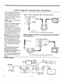
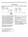
CATV (Cable
The connection illustrations
shown in Figures 1 and 2 show
the common methods of connecting your VCR to cable service and your TV set.
TV) Converter
Box Connections
Figure 1 CATV "Converter
VCR
Figure 1. (Not recommended
for VCR Plus)
BACK
After" VCR Connections
PANEL
VH F_,dHF/_TV
If your CATV cable connects
directly to your TV (with or
without a converter or
IN
@
descrambler box) you may use
the connection method shown.
You will not be able to record
an unscrambled (Pay TV) program with this connection.
CATV
OUT
Converter
Box
Cable
Note: Select all channels for viewing/recording at the cable box.
Figure 2. (Recommended for
VCR Plus) Using this method
you should be able to record
Pay TV programs with your
VCR. You will only be able to
:record and view one channel ata-time with this connection.
Figure 2 Cable TV (Pay TV) To Converter Box To, VCR To TV
Set Connections
CATV
Cable
Note:
For special cable connections
please refer to your cable
I
company's
'-(_)
service department or
a qualified IV' Technician.
IN
OUT
Converter
Box
"Youmay need additional adapters to make the connections
shown.
Note: Select all channels for viewing/reco_rding at the cable box.
System Diagram
Camcorder
_To,.
__
rh--rl
P-tl
=L"
To
Audio
Aualo
Video
_l.
rl
.-
,.
In-_
Stereo
(
.,tllll
ANT
ANT_
INto*
Anfenna
or
Cable
z_;lvo
I
OUT
Cablo
Box
I_
I@
''
I
I
I l
4 -2 3
I I
/
If
I
m= _
_N]"
UT
VCR
•
•
AUDIO VIDEO
IN
IN
ANT"]
IN _m
I [
_
I
Tv
J
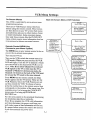
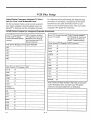
VCR Menu Settings
C)n-Screen
Menus
:['his VCR is controlled
programming
system.
Main On-Screen
by an on-screen
Menu (VCR Features)
menu
Date
"]['here are 5 VCR Feature menus which you
choose using the remote control. These menus
are then shown on your TV screen. Each menu
and sub-menu asks you to either make a choice
or enter information.
Some on-screen menus
have only three screens, like the CLOCK SET
raenu, others
to be entered
-->1-Enter
month/day/year
Example:
03/08/93
key
r
÷
Press numberXcy
1 Clock Set /
VCR Features j
2 Program Record
3
--> 1-Enter
date
(Use ADJUST to erase)
,_ 2-Press ENTER key
_rogram 1 to record •
Month 3/Day 8
Start L'05AM/_op Z'O5AM
Aux input/Speed SP
Record:D_ai__
_(blzD......
-_ 1-Pr_s SELECT key to
see next program or
Press 'O' key to
erase this program
\
control to
\
Ch-3. Note: If you chose Channel 4 to send your
VCR signals to the TV set then tune the TV to
Channel 4. Whichever
decision you made, the
Channel 3-4 Switch on the back of the VCR must
be set and the TV tuned to the same channel
program
Example: 03/08
To quit press
VCR mode. (When you press any key the VCR
LED will light.) Tune the TV to channel 3. Make
sure the switch on the back of the VCR is set to
-
_
4 Tuning Features
5 VCR Setu
is the ac-
•
Month -/Day
Turn on your TV set.
Tuning Features
•
)Press number key
1-Tuni ng Band
2-Auto Channel Search
\
\
Press MENU on the remote control; the Main
Menu appears on the TV Screen. These are the
VCR Features.
Once the VCR Features are set
up they control the VCR. To choose a feature
press the number key on the remote control that
corresponds
to the number of the menu item. For
example, press 1 to bring up the CLOCK SET
menu, press 2 to bring up PROGRAM
RECORD
etc.
3-Channel Save/Skip
4-Source Select
To quit press QUIT key
•
VCR Setup
-->Press number
l-On-Screen
For the menu system to be accurately functioning
the clock/date
must be set correctly.
Note: If you program the VCR with information
and then disconnect
the power cord from your
wall socket some of that information
will be lost.
key
Display
To quit :press QUIT
If a power failure occurs the result is the same as
if you disconnected
the power cord.
2613-O
to erase
/
Fiemote Control MENU Key
(,Access to your Menu System)
The MENU key on your remote control
cess to the on-screen menu system.
(Use ADJUST
2-Press ENTER
//
require more information
that has
or chosen on several screens.
Turn on the VCR; switch the remote
Set
Month-/I)ay-/Year-
5-1
key
VCR Menu Settings
:Set the Current
Time
Press 4 to choose
:Set the clock on the front of the VCR in the mes-
]Menu (VCR
screen.
Features)
Press SELECT to move to sub-menu AUTO
CHANNEL. SEARCH.
control.
This will bring you to sub-menu
DATE
VCR Tuner Channel
SET.
Set the Month
The first two numbers
would be the month.
the month by number;
the remote control.
use the numbered
For example April, the 4th month
would be entered as 04, December
Enter
keys on
of the year,
the 12th
The VCR has automatically programmed itself to
receive those channels. Press QUIT on the
remote control; the first channel's program will
appear on your TV screen.
Programming
Tip: If you are having difficulties
press QUIT, then re-enter the Main Menu by
pressing MENU on the remote control to start
Note: Make sure
VCR On-Screen
channel number
upper right hand
time you change
over.
Set the Date
q_e next two numbers would be the date. For example 03 would be the 3rd day of November. The
last two numbers are the year. For example, 1994
would be entered as 94.
PM. For example 9:35 in the morning
entered as 09 35 AM.
would
Fleceiving VHF/UHF
1V Service
or Cable
TV Programs
Select Channel 3 on your TV to receive
programs from the VCR Tuner.
be
televised
Press MENU on the remote control to bring up
the Main Menu (VCR Features) on the TV
screen.
you have chosen ON from the
Display sub-menu so that the
will appear momenrarily in the
corner of the TV screen each
channels.
As you press CHANNEL Up or Down each channel the VCR has found 'will be shown on the TV
screen and the channel :m:tmber will also be
shown in the VCR message center.
Set the Time
Enter the hours, then the minutes, then press
AM/PM on the remote control to choose AM or
Search
Press ADJ to begin the VCR automatic channel
search program. The VCP, searches for the available channels you receive in your local broadcast
area. When the search t)rogram is cornplete the
channels that were found will be indicated as
CHANNELS FOUND and be followed by the
number of channels that were found. For example, CHANNELS FOUND 14.
month of the year would be entered as 12. If you
make an obvious mistake the on-screen display
will show a ? where the correct number should
be. Press ADJ to erase errors.
_,61vo
menu for
Press ADd to choose TV if you only receive
UHF/VHF
CHANNELS.
Choose CATV if you
have cable service.
control. The Main
appears on your TV
2. Press I on the remote
FEATURES.
Press 1- Tuning Band. The on-screen
TUNING BAND appears.
:;age center. Use the VCR remote control to
place the on-screen display on your TV screen.
1. Press MENU on the remote
TUNING
Some channels may be too weak to send a picture
(adequate viewing signal) to the VCR.
To eliminate these channels in the channel
memory sequence that the VCR has tuned, write
down the numbers of these "weak" channels and
proceed as follows.
Channel Save/Skip
I. Press MENU on the renaote control.
2. Choose
TURES.
5- 2
main menu it,...na4-TUNING
FEA-
VCR Menu Settings
3. Choose
CHANNEL
SAVE/SKIP.
Each chan-
f
nel the VCR tuner has found will come up in
numerical sequence. As you press CHANNEL
up
choose SKIP to delete any weaker channels as
desired. Choose SAVE to keep the channels with
an adequate signal. Repeat this procedure
to
eliminate any other weak channels. For example,
if Channel 27 comes in but is too weak for view-
STOP
SP
ing, press ADJ so the word SKIP appears next to
tire weak channel's number. Press QUIT on the
remote control when finished with the Channel
15 Mon
7:17 AM
SAVE/SKIP
procedure.
Now when you press the
CHANNEL
Up/Down keys only strong signal
channels will be tuned in and weak ones skipped
using the VCR tuner. Tune channels with a cable
box at the cable box.
Choosing
15 Mon-
1:35:45 -- Tape position :indicator is :at 1 hour, 35
minutes and 45 seconds.
Power Failures
Occasionally a power failure occurs. "]['heresult is
that all the information programmed into the
VCR has to be re-entered'. If you were away
when this occurred and notice that the clock date
directly (32 for example) and pressing ENTER to
switch the VCR Tuner to receive that channel.
The channeI number will be shown in the upper
right hand corner of the VCR on-screen display
which will appear momentarily on your TV
screen each time you change channels or initiate
a VCR operation.
and time are missing and :SET CLOCK appears,
then there was an interruption in electrical service to your VCR.
Error Messages
As you use the menu system, if a problem or conflict occurs the menu system alerts you with an
error message on the TV ,;creen, like "'No Cassette." For example, if you entered all the information for a timed recording and pressed the
TIMER key to set the VCR into TIMER Mode
and no tape was loaded :into the tape loading compartment, then that error message would appear
on your TV :screen.
Display
The TV 4-corner VCR status on-screen
display
shows the channel you chose using the VCR
tuner, and also the function the VCR is performing, PLAY, RECORD,
STOP, etc., will be displayed on the TV screen for a short time.
VCR Status On-Screen
STOP--
the VCR is in the Stop Mode.
Indicates
SP -- Indicates
Play.
261_-o
The date the VCR is set aL
7:17 AM - The time the VCR is set at.
choose a channel by using either the CHANNEL
Up/Down buttons on the VCR or the remote control, or by using the numbered keys on the
remote control to choose the channel number
T3_pical 4-Corner
1:35:45
VCR CH 11 - Indicates VCR mode is active and
the VCR Tuner is set to Channel 11.
The remote control must be set to the VCR
mode to choose channels on the VCR. You can
On-Screen
CH 11
J
Channels
VCR Function
VCR
Display
tape speed is set for Standard
5-3
VCR Message Center
Message
Center
Displays
The messages
of information
3Nis display panel enables you to understand
what function the VCR is performing
at any time.
Designed to be self-explanatory,
these messages
are displayed automatically.
Message
:Display
Center
changes will be visible on both the TV screen and
VCR Message Center.
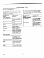
Message
Video Recorder
Operation
:SET
Record
Indicates video recorder
Center
Display
'Tuner Messages
CHANNEL
has
Appears when you turn on
the VCR.
SAVED 3
Indicates channel 3 is saved
in Channel Scan.
SKIPPED 7
Indicates channel 7 is
skipped in Channel Scan.
CHANNEL
Indicates VCR tuner is
tuned to a specific channel.
AUX
Indicates video recorder is
tuned to receive both video
and audio signals from the
video in and audio in jacks.
Setup Messages
SET CLOCK
Indicates clock needs to be
set. NOTE: This message
appears ff power to the
video recorder
Operating
is interrupted.
Indicators
Indicates the video recorder
is in the VCR Tuner mode
or a tape is playing in the
VCR.
[-_
2613-o
Indicates a VHS cassette is
loaded in the video recorder.
5 -'4
Video Recorder
iOperation
Messages
NO CASSETTE
Appears when TIMER is
pressed and there is no
VHS cassette in the video
recorder.
NO TAPE TAB
Appears when REC ITR is
pressed and the VHS
cassette inserted in the
video recorder has no safety
tab.
completed auto channel
search.
HELLO
in the display may be duplications
shown on l:he TV screen. Some
I
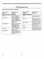
VCR Message Center
Message
Center
Displays
(Continued)
m
Message
Center
Display
Record
Operation
Messages
REC CH __
"RECORD 0:0(3,
TAPING
Message
Display
Video Recorder
DONE
Playback
(Continued)
_LAY X2
Appears when the video
recorder is placing an index
mark at the beginning of a
AUTO TRACK
is
ndicates video recorder
is
Indicates the video recorder
_; automatically adjusting
the tracking control.
recordltlg.
2612-o
Indicates video recorder
l:,laying a tape at double
rLormal playback speed with
:,icture but without sound.
Appears when the VCR has
finished all recording
assignments. If necessary,
press TIMER to release
VCR from Timer mode.
INDEX MARK
Messages
:,laying a VHS cassette.
Appcarswhen REC ITR is
pressed, prompting you to
select the desired amount of
Instant Recording Ttme with
successive presses of
REC ITR.
Appears when Timer is set
and power is off.
_(Tideo Recorder
)peration
PLAY
Appears when the video
recorder is recording.
TIMER SET
Center
5- 5
STOP
Indicates the video recorder
i.; in the Stop mode.
FFWD
Indicates the video recorder
L_in the Fast Forward mode
(without picture or sound).
I
VCR Message
Message
Message
Center
Displays
Center
l)isplay
Playback
(Continued)
Video
Recorder
Operation
Messages
(Continued)
REW
Indicates the video recorder
is in the Rewind mode
without picture or sound.
FWD SEARCH
Indicates the video recorder
is in the Forward Visual
Search mode.
REV SEARCH
Indicates the video recorder
is in the Reverse Visual
Search mode.
BLNK SEARCH
Indicates the video recorder
is in the Blank Search mode.
STILL
Indicates the video recorder
is in the Pause mode.
SLOW
Indicates video recorder is
playing a cassette in slow
motion.
INDEX
Indicates the video recorder
is in the Index Search mode.
Tape Transport Messages
EJECT
Indicates VCR is ejecting a
tape.
ERR
Indicates the VCR has
detected an error in
accepting a cassette. Take
the VCR to a Zenith
approved
z+t._o
service center.
5- 6
Center
I
Playback
,m
PLAY
D
/
"It
$P-LP-EP
•
Turn
iV
Switch
.
/
_ /
_SPEED_;E_CH_ I
__
_
i
i=n..-1
/ €:
/
,,
)
PAUSE
I
/
REC IIR
the
TV
on
the
remote
and
tune
remote
it to
to operate
control
to VCR
ON
SCREEN
channel
3.*
(If
your
TV,
PROC, RA_G'-I
you
3,
press
mode.
OFF
Note: The symbols shown on this illustration
in the
VCR message center will only appear while the VCR is
performing
those functions.
However, the clock will
remain on while power is supplied to the VCR.
ENTER
on
the
* Or 4, the same channel that you set with the CH 3-4
switch on the back of the VCR to send the VCR signal
to the TV set.
6- 1
QUIT
® ®@
® ® ,®
® ® ,®
CHANNEL
VOLUME
VCR PLUS _4MAP
a
Display Elapsed Time- Press ENTER on the remote
control; press it again to leave the tape counter display
on the TV screen.
Display-Press
o
SELECT
To stop playing the tape, press STOP on the VCR or
the remote control. Press EJECT on the VCR to eject
the tape.
To Remove
Counter
remote
control.
-tD
loading comthe tape will
safety tab has
VCR or the
Automatic
Reset-The
counter resets when you insert
tape and when a tape is rewound to its beginning.
_i_o
JL____
;
3. Insert a VHS cassette tape into the VCR
partment;
this turns on the power and
automatically
begin playing if the cassette
been removed,
or press PLAY on the
remote control to start playing the tape.
°
_ /
/FFWD
VRL4170-,4HEAD/_(D
•
programmed
the
then ENTER.)
.
REW
//c____
L-CHANNELJ
(
/
STOP
li _
=1 c-_T
CS_D C=D
RE:W
_
F FWD TV/VCR
.I
I
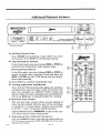
Additional Playback Features
PLAY
D
rl
II
U
STOP
/
/
REW\
FFWD
(,It44
\ J[ !
_
/ _SPEEC_SE_ I'RCH'-J
3
I
I
;
Corm_l
LCHANNEL
(
_ET ELC1EK
-J
11
SP-LP-EP ][
C--_-
-
oNscott. P,ocR,...N_-.Qj --I /
REC
_AITR
4_-
J
A. Still/Slow
Motion
-}
\
!
_ /
!/ \/ .,J
Video
Press PAUSE
while playing a tape, follow on-screen
instructions.
Press PLAY to resume tape playing.
B. Tape Rewind/Fast
Forward
In the Stop mode, press and release REW or FFWD to
rewind or fast forward the video cassette tape.
Reverse/Forward
PLAY to continue
D. Tracking
Adjustment
watching
Time
Tape
Auto/Manual
Counter
The real time tape counter
shows you the amount
of
time that has elapsed
from the start of the recording,
or playback,
in actual
hours,
minutes
and seconds.
(1:3'i:28 = 1 hour, 35 minutes
and 28 seconds).
Counter
Memory-Press
MEMORY on the remote
trol, follow the on-screen
instructions.
F. Index
2613-O
Search-(See
Additional
SELECT
®
the tape.
Your Zenith
VCR automatically
adjusts for optimum
tracking
every time you play a tape. If however,
the
tape was recorded
on a different
VCR, streaks
may
appear.
While the tape is playing, press and hold down
one of the ADJ keys to manually
adjust the tracking.
E. Real
OF'F ON
0
Search
In the Play mode, press and release
REW or FFWD to
search the video tape recording.
If you hold down the
REW or FFWD key the VCR will go into Jet Search,
faster tape scanning.
C. Press
C_--7C_D
con-
Operations)
Note: Press ENTER two times to leave the tape counter display on
the TV screen in each mode; STOP, RECORD,
PLAY etc. (Not
available in all modes.)
6-2
QUIT
im
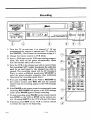
Recording
PLAY
•
REW
D
;ETELaC
o_
STOP
Irl
F FWD
VRL4170-4HEADS
(DA)
SCREEN
PROGRAMMINO-HC
1. Turn the TV on and tune it to channel
3.* (If you
programmed
the remote
to operate
your TV, press 3,
then ENTER.)
*See Footnote
at the bottom of page 6-1.
2. Change
the remote
control
to VCR
Mode.
3. Insert a VHS tape into the VCR tape loading
compartment;, this turns
on the power
automatically.
Make
sure the cassette
safety tab is intact.
4. Tune the VCR to the channel you wish to record. Note:
For recording
CATV (cable) broadcasts
the cable box
must be on and tuned to the channel
you wish to
record.
The recording
speed
will be SP (Standard
Play)', to select a different
speed press SP/LP/EP
to
enter
the speed selection
sequence.
(See Additional
Operations
for recording
speed chart.)
5. Press and hold Ri=G ITR on the VCR or RECORD
on
the remote
control
until
REC CH and the channel
number
center.
you are recording,
appear
in the VCR
message
6. Press PAUSE on the remote control to momentarily
cease
recording,
REC PAUSE will appear in the VCR message
center, press PAUSE again to resume recording.
7. To stop recording,
press PAUSE on the remote
control
then STOP on the VCR or STOP on the remote
control. (Pressing
EJECT on the VCR will eject the tape.)
8. If desired,
to rewind
2_,L'.-O
press FlEW on the VCR
the tape to the beginning.
or remote
7- 1
control
[]
SELECT
QUIT
®
®®®
Q ( .,,:R)
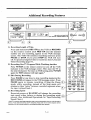
Additional Recording Features
PLAY
D
II
LCHANNELJ
•
STOP
c----r--_l
c----_--3i
L-SPEED
•
_ J
,*
? i
SEARCH-J
i
)
xErCL CK o.
,
.-EP I] RE_I_
A. Recording
Length
of Time.
Press and hold down REC ITR on the VCR or RECORD
on the remote control until REC CH and the channel
number you are recording,
appear in the VCR message
center. The VCR will continue recording
until you press
PAUSE or STOP. If you press STOP the VCR will turn
off. To specify a length of time to record see item A. Instant
Timer Recording page 8-1.
rwq r_-q
©
SELECT
_i_o
7- 2
n.ASHBK
CHANNEL
®®®
VOI.UME
® ( -,- )
(ZZ)
CZ)
CZD
VCRPt.US CHMAP
•
---
Repeated
presses of SL/LP/EP will change the recording
tape speed either before or during the recording
setup
process. (See Additional
Operations,
for Tape Recording
Speed Chart.)
° Cable "IV companies that supply subscribers with a converter/descrambler box use a wide diversity of
antenna, VC'R, cable/converter box to TV connections. Please refer to your cable company's service
department
for their options available for recording/watching
the same program.
QUIT
®®®
®®®
Recording
Press PAUSE at any time to stop recording
momentarily;
REC PAUSE will appear in the VCR message center. Press
PAUSE again to resume
recording.
(Using the Pause C(_
mode, while recording,
instead
of the Stop mode will
eliminate video "noise" between recorded
segments when
the tape is played back.)
D. Recording Speed
©
SOJRC£
B. Recording One TV Program While Watching Another
Press TVNCR on the remote control to turn off the VCR
indicator in the VCR message center. Then tune the TV to
the desired channel. To return to VCR tuning, press "D//VCR
again the VCR indicator will light again.*
C. Edit During
OFF ON
[,
STOP
MUTE
RMJS_ SF..ARCH
,r_ _
II
I
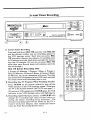
hi_tant Timer Recording
m
0
B
RI_M
F FWD
I.--$PEED SEA,rICH--J
PLAY
STOP
(
(
•
J[
•
)
m=
PAUSE
rE T _FLDD(
LCHANNEL -_
ON
SCREEN
PROGRAMMING-HQ
L,
A. Instant
Press
Timer
and hold
,i
Recording
down
REC ITR one time
until
REC CH
and the channel
number
you are recording,
appear
in
the VCR message
center.
Each
time you press
REC
ITR thereafter
chooses
the amount
of recording
time
in 30 minute
intervals.
Each press extends
the recording time 30 minutes.
(If you do not press REC ITR
more than once Record
mode will continue
until the
OfT
0
end of the tape.)
REC
ITR Button
SELECT
Recording
One TV Program
While
QUIT
O ® @
Time.
2 Presses
30 Minutes,
3 Presses
1 Hour, 4 Presses
1
Hour 313Minutes,
5 Presses
2 Hours, 6 Presses 2 Hours
30 Minutes,
etc. up to a maximum
of 4 hours. The time
you choose will be displayed
in the VCR clock area and
will count down until recording
time is over.
B. Recording
)
Watching
Another
Press TV/VCR on the remote
control
to turn off the
VCR indicator
in the VCR message
center. Then tune
the TV to the desired
channel.
See CATV note page 7-1.
<D ® @ DQ
@ ® @
@ C-,-)
lrli_
Yr..R_
q_l-iOIAP_ MIJTE
TIUER
(To return to VCR tuning, press "rv]vGR again, the VCR
indicator
in the VCR message
center will light again.)
C, Recording
Speed
Multiple
presses
of SP/LP/EP
will
change: the recording
tape
speed
either
before
or
during the instant
recording
setup procedure.
The
selected
recording
speed will be shown on the TV 4Corner
On-Screen
Display.
(See Additional
Operations, for Tape Recording
Speed Chart.)
26_3-o
8- l
--3
1
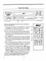
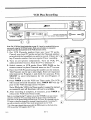
Timer Recording
PLAY
STOP
c --_- i[--_--) i
( _
I[--_-- )J
L-SPEED
;_;EARCH'_
"
(
!
EP
P.usE
to have the program
1. Turn
the TV on and tune
to channel
3.* (If you
programmed
the remote
to operate
your TV, press 3,
then ENTER.)
=See Footnote
at the bottom
of page 6-1.
the remote
control
OFF ON
-0
to VCR mode.
3. Insert a VHS tape into the VCR tape loading compartment. If this is a new tape it will be cued to start at the
beginning;
if this is a previously
recorded
tape, advance
or rewind
the tape to the position
where you want to
begin recording.
4. Press MENU on the remote control to bring up the Main
Menu
(VCR
Features).
Press 2 to bring up Program
Record.
Follow the on-screen
instructions,
and enter the
recording
information
for Program 1; check for accuracy
when complete.
5. Enter
the information
for Program
2; if there
is one.
Check Program 2 information
for accuracy,
etc. Press 3
to bring up Program
Review,
if needed,
to check for
accuracy what you entered
for Programs 1 and 2, etc.
6. When programming
is complete
press TIMER
on the
remote
control
to set the VCR in Timer mode; TIMER
SET' will appear
in the V.CR message
center.
When
recording
assignments
have been
completed
TAPING
DONE will appear in the VCR message
center.
If necessary, press TIMER to release
the VCR from Timer mode.
Note: While the VCR is operating in the Timer mode it cannot
be turned on or off manually, and other features available in
modes like PAUSE and STOP, will not be available.
261_o
2
2E_1112
Note: The clock/date must be set correctly
recorded at the right time.
2. Change
I
) I
9-i
(=D
SOURCE
()
FLASHgI<
,/
SELECT
QUIT
®®®
CHANNEL
N
YOLU_E
G
(
EITI-'R
)
(S=D CZD CZD (_D
CZD OED CS_D C=D
RR.CORO STOP
PL_
_
S_kRCH
F FWO "rv/VCR
I
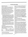
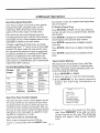
Additional
Timer Recording
J
Program
Review
f
Program
/
J
Channel
- will be :;elected
automatically
if
automatically
if you
specified CATV in the Tuning Features,
Tuning Band submenu before you entered
the Timer program.
Aux Input - must be specified to record
radio broadcasts or to use a surveillance
camera connected to the VIDEO/AUDIO
2:30AM
_
1 - Press SELECT k_,,
Recording Speed
to see next program
SP - Standard Play is the best for video
reproduction.
erase this program
or
LP - Long Play will extend the recording
time available on the tape.
x,
EP - Extended Play will triple the recording
time over Standard Play.
Note: To quit press QUIT key
Tape
FM
input jacks on the ba,=k of the VCR.
Press 'O' key to
Automatic
Band
CATV - will be selected
Chafi/nel 11/Sp eedSP
\
/
Tuning
you specified TV in the Tuning Features,
Tuning Band submenu.
1 to/record:
Month 3/fl_ay 8
Start lz.00AM/Stop
Operations
Switching
If you are using Timer Recording
to record a
program at SP (Standard
Play) speed, and there
i,; not enough tape to complete the recording,
tlne VCR will automatically switch to EP (Extended Play) speed. There will be some distortiion in pictazre and sound at that point on the
tape. The VCR will switch to EP Speed when
there would be 10 minutes of tape left at SP
speed, giving you 30 minutes of tape left at EP
speed.
Recording Selection
Once -- will record a broadcast one time.
Weekly - will record a broadcast
each week.
one time
Daily --will record one broadcast, one time
each day, Monday through Friday.
The VCR Timer automatically sorts through
the recording information and sets up the
broadcasts based on starting times.
Note: If recording l:iraes overlap, the onscreen menu system alerts you to that fact as
you are programming the VCR for recording.
2,ns-o
9- 2
I
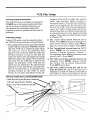
VCR Plus Recording
0
l
II (
P LAY
STOP
REW
F FWD
•
II
•
_.-SPEED
SEARCH--J
C
"
|
?
)
PAUSE
JI
\_
LCHANNEL_
(
li
N
6
SP-LP-EP
REC I_R
rE T [LBEK\, m
] ON
PM
II v,0
1
VRL4170-4HEADS
(D
SCREEN
PROGRAMMING-I
J
\"
Note: The VCR Plus Setup beginning on page 11-1 must be completed before you
can record using the VCR Plus feature. Make sure all cables are connected
properly and that the date!time in the VCR clock are correct.
1. Get
VCR
Consult
Pluscode
number
from
your
local
your local TV guide and get the Pluscode
printed
with the broadcast
you want to record.
any Pluscode
number then use regular Timer
2. Turn
on all
cable/converter
3. Switch
remote
TV
guide.
number
If there isn't
recording;.
OFF ON
Z)
C:D
system
components.
Turn
on VCR, TV,
box etc. Tune the TV to Channel
3".
remote
control
to VCR
to place
SOURCE
©
N
®®(D
N
(9@(9
@'® (D N
/G) @D
N
mode.
Press VC8 PLUS on the
Pluscode
menu on the TV screen.
FLASI-IBK
SELECT
CF_NNEL
4. Enter the VCR Pluscode using the numbers on the remote.
The Pluscode can be up to nine digits. Enter all requested
information
for Program 1 and check for accuracy. Press
SELECT
to enter
there
is one.
5. Press
TIMER
will remain
pear
information
the
next
Program';
to set the VCR
VCR
4_
the VCR is in Timer mode it cannot be turned
and all functions
will not be available.
_/
(
off until broadcast
into
Timer
time;
center
6. After recording
is complete,
release
the VCR from Timer
mode.
The
TIMER SET will ap- (
window.
if necessary,
mode.
press
TIMER
to
Note: A recording/viewing TV option is to use the I'VNCR key on your remote
control to switch the TV screen image from the picture being received by the
VCR tuner to the picture being received by the TV Tuner, then manually use the
TV tuner to select the channels for viewing. Using this method of watching TV,
you will not interfere with the Timer mode programmed into the VCR.
* Or 4, the :same channel that you set with the 0H3-4 switch on the back of the
VCR to send the VCR signal to the TV set.
2_lJ_o
VOLUNE
if
/
in the VCR message
Note: While
on manually
for
QUIT
10 -- 1
{'5_
!
/
L
i:_'_; ,"
ko_
l
VCR Plus
Recording
programs to be broadcast ,an that day, are contained in a 24 hour listing. Each program has its
own Pluscode. Use the l?luscode specified for
VCR Plus Description
VCR Plus is a quick method of programming your
VCR to record while you are away. When you enter
the 9 (or less) digit Pluscode the VCR automaticallly enters the start time, stop time and selects the
channel number of the broadcast you wish to
re.cord. All you have to do is select the recording
speed and whether you wish to record the broadcast
Once, Daily or Weekly. When the time of the broad_LSt arrives, the VCR automatically tunes to the
channel of tile broadcast, or tunes the channel on
file cable/converter
box (if you have one).
Note: Cable/Converter
each program
weekly.
than Monday use the Daily or Weekly recording
modes to eliminate the pc.ssiblity of receiving an
error message. After the broadcast(s),
simply
erase the remaining programming
information
from the VCR's memory. Press MENU, Choose 3Program Review, Enter 0 to erase programming
information.
Box Users
a Cable/Converter
Plan Your Recording
BoX
When you plan your recording week, the recording sequence may call for inserting several different tapes, at different times or on different
days. For example, if you plan on recording a program Monday, Wednesday and Friday while you
are away- a soap opera perhaps. But also want to
record a mini-series broadcast on Tuesday and
Thursday 7 to 9pm, you probably would want to
use different tapes for each. In this scenario
record your daytime program Monday. Take out
that tape and insert a different tape for the first
part of the Mini-series recording. Reinsert the
tape with the Monday program and record the additional program on Wednesday. Take out that
tape. Reinsert the Mini-series tape to record on
Thursday, and so on. In this way the TV can be
If you do not have cable you can still use the VCR Plus
feature to record over-the-air programs. If necessary,
channel map for your local broadcast area. If you do not
do the Channel Map procedure the broadcast you record
may be from a different station than the one you intended.
VCRPluscodes
These Pluscodes are printed in your local TV
guide with each program description.
This nine
digit (or less) Pluscode number may be included
with each program.
t ,IAX
Wilderness
13569
7:00pm
Comedy 2468927
VCR Plus Recording
Air War 27689957
7:30pm
Journal 34567821
Notes
used
with the
tives; programs
record.
Some local TV guides publish program listings
for an entire week. Each 24 hour day and the
2_,13-O
Times.
Although your VCR can be programmed
to
record up to 8 programs; at a time it may be advantageous
not to enter that many programs at
one time.
If you do not have a cable box, but you subscribe to CATV,
you will still have to program your VCR to receive VCR
Plus listed channels. If you do not do the Channel Map
procedure the broadcast you record may be from a different station than the one you intended.
tBO
once, daily or
Other TV guides publish the daytime programs;
soap operas, serials etc., only on Monday, with
the VCR Pluscodes listed only for that day; the
Tuesday, Wednesday,
Thursday and F:riday Pluscode listings for those programs
(since they are
mostly repeats) are omitted to save space. To
record broadcasts with Pluscodes on days other
This VCR will control most models made by different
cable/converter
box manufacturers. However it may not
control all the models of all the cable/converter box brands
currently available in the marketplace. Also, some older
model cable/converter boxes are manually controlled; they
cannot be controlled by this VCR. Speak with your cable
company about an IR (Infra-red) controlled cable box.
Notes: Users Without
you wish to record,
10-2
VCR
tuner
for your
viewing
alterna-
you will watch but do not want to
VCR Plus Setup
nal path of the VCR or cable box, such as
coffee
cups, ashtrays,
books,
etc.(See
illustration
below.) Note that the cable/converter box is located
on the top and at the
front of the VCR. Note that the signal sent
out by the VCR is _,eing reflected
off the
reflective
surface or wall and bounced
back
VCR Plus Setup Introduction
"]?heVCR Plus setup is as simple as pressing the
CH MAP key on the remote control and followi:ag the on-screen instructions.
However, you
raust perform the preliminary
setup and be
prepared
to answer or perform the on-screen instructions.
Preliminary
to the cable/converter
box signal receiving
window. Note that the cable box has tuned
to Channel
59.
Setup
2. The source select
option must be set to
Tuner. Press Menu, choose
4-Tuning
Features. Press 4-Sourc,_
Select.
Press ADJ to
Certain VCR options must be selected to allow
the VCR Plus Setup procedure
to be performed.
1. The cable/converter
box and the location
of the VCR are critical
to VCR Plus record-
place
the arrow
=
TheVCR's
correctly.
Set,
Press
Sa
follow
QUIT
clock
Press
the
when
date
and
MI'NU,
on-screen
done.
time
must
choose
be set
1-Clock
instructions.
Channel 3; set CH 3-4 switch on the back of
the VCR to 3. Note: If you chose to set the
Cable Box and Signal Receiver
Window
Cable
Box
Surface
VCR
261.O
be CATV.
control.
The VCR, cable/converter
box and TV set
must be turned oa. The TV must be set to
VCR and Cable Box Location/Relationship
Reflective
QUIT.
Choose
4-Tuning
Features.
Choose
1Tuning Band. Press ADJ to place the arrow
next to CATV. Press QUIT.
signal is sent out by the VCR and reflected
off most surfaces
in such as way that the
cable box wiI1 receive the signal from many
different
angles; the signal will literally
fill
the room. For the cable box to receive
this
signal,
the positions
of the VCR and the
cable box are important.
No obstructions
should
be in the path of the receiving
window on the cable box, or in the path of the
sending
window
on the VCR.
In other
words,
do not place any objects in the sig-
Wall or _ny Other
Press
3. The Tuning Band selected
must
Press
MENU on the remote
ing. The VCR has a window through
which
the codes are sent to the cable box. This
VCR and Signal Sender
next to Tuner.
11 -1
m
i
VCR Plus Setup
,
CH 3-4 switch on the back of the VCR to 4,
then tune the TV set to Channel 4.
the cable box: should then tune to Channel
Channel 59 should remai_ selected.
The cable/converter
box output wire must
be connected
to the VCR ANT IN jack on
the back of the VCR to be able to use the
If the first number does not work, try the other
"MFR" numbers for your (:able brand in sequence; try the next, then the next etc. If none
work try relocating the cable box and VCR to a
different location or relationship. If you have successfully placed the components, the cable box
will automatically tune to Channel 59 and Channel 59 will remain selected.
VCR Plus feature.
(See
page
4-3, Figure
2.)
VCR Plus Setup
Channel
Map Procedure
1,. Press CH MAP
Press CH MAP on the remote control; follow the
on-scl'een instructions, answer the questions and
enter the requested information.
Choose 1- CH Map Setup.
.4mswer question, Do you have a cable box?
If No, proceed to page 11-3 Step 4, Channel Mapping.
If Yes, you may have to turn the cable/converter
box on manually when you want to use the VCR
Plus recording feature.
If yes, is cable box connected to VCR "ANT IN"?
As mentioned in Preliminary Setup, the VCR
must be connected to the cable/converter box as
dietailed on page 4-3 Figure 2, to be able to
record premium channels.
2. Enter Your Cable/Converter
Channel Number
Box Output
The cable/converter box output channel number is
usually 3 or 4; the number could also be 2, 5, or 6.
Note: This number may be printed on the
c.able/converter box back panel or in the
cable/converter box operating guide. If the number is not located in either place then call your
(:able company and ask them for "The Cable Box
Output Channel Number."
;3. Enter Your MFR Number
]Enter your "MFR" number from the list on page
:l1-3; the system test is automatically initiated and
:,613-o
59 and
Note: These MFR numbe rs were determined by
the Gemstar Corporation from tests with most
popular cable boxes and then compiled and
presented in list form for manufacturers who are
employing the VCR Plus technology.
The manufacturer's name could be printed somewhere on your cable/converter box. Lx)cate the
name in the MFR Number List on page 11-3 and
write down the 1 or 2 digit MFR number on a
sheet of paper. Some mmiufacturers :mayhave
more than one number. Write down all the MFR
numbers for' your partkm]tar cable/converter box
manufacturer. One of these MFR numbers may
be accepted to program the VCR to send the signal that will control your cable box. If your cable
box does not have a manufacturer's name, call
your cable company and ;ask for "the Cable Box
Manufacturer's Name."If none of these numbers
work enter 99 for the MFR number; the VCR
will not control the cable box.
New MFR Numbers
The MFR Number List on page 11-3 is a current
listing of all available MFR numbers to date. If
your cable/converter box does not tune to Channel 59, perhaps a newly created MFR number
will work that has not yet been published. In this
case try entering all MITI_[numbers starting with
number 1 and continue through MFR number 83
to see if the cable box will tune to Channel 59,
and have Channel 59 remain selected.
11 .- 2
I
VCR Plus Setup
MFR Number
List
Archer
1, 29, 42, 44, 76
29
Cabletenna
42,44,63
Cableview
44
Century
30, 42, 44, 52
Citizen
Curtis
8, 9, 56, 61
Diamond
29, 44, 76
Drake
37, 67, 71
13, 20, 21, 22, 23,
Eagle
28
Eastern
57
General Electric
General Instruments:
1, 2, 3, 4, 34, 55,
GC Electronics
: 42,44,63
Gemini
4, 3O
44
Gerrard
14, 15, 28, 41
Hamlin
Hitachi
31, 79, 80
Jerrold
1, 2, 3, 4, 34, 55,
Jerrold Starcom
: 1,3,4,55
IVlacom
31, 79, 80
13, 20, 21, 22, 23,
Maganavox
16
IVlatsushita
32, 38, 39, 40, 60
IVlovietime
32, 38, 39, 40
NSC
Oak/Oak Sigma
: 10, 11, 12, 13, 46,
Panasonic
6, 16, 17
13, 20, 21, 23, 24
Philips
Pioneer
5,6,78
Pulser
42, 44
Quest
78
RCA
6, 16, 17
Realistic
44,51,53
44
Fl:ecoton
14, 23, 41
Fi;egal
28
Fi',egency
Rembrandt
29, 32, 42, 44, 60
4, 6, 42, 78
SL Marx
_l. Channel
25, 58, 62
75, 83
75, 83
25, 26
ZenRh
47
Mapping
The last step is Channel Mapping. The listed
channel numbers in your TV guide may have to
be mapped to the local cable company's "assigned" TV channel numbers for your cable
company's broadcast area. Change each listed
number to your cable company's assigned number as required.
LISTED
TV Channel
These listed
channel
Numbers
numbers
used in the VCR
Plus system are ordinarily included in your local
TV guide and may be called VCR Plus Channel
Numbers. You may find them in a separate VCR
:_lro
Salora
Samsung
Scientific Atlanta
Sheritech
Signal
Sprucer
Stargate
Starquest
Sylvania
Teknika
Telecaption
Teleview
Texscan
Tocom
Toshiba
Uniden Satellite
Unika
Universal
Videoway
Vid Tech
V'_ter
Viewstar
:
:
:
:
:
:
:
:
:
:
:
:
:
:
:
:
:
:
:
:
:
:
68, 72
4, 6, 32, 42, 78
8, 9, 56, 61
27
26
6, 16, 17
4, 6, 42, 44, 78
6
19
54,74
77
4, 6, 40, 42, 78
18, lC_
1, 33, 34, 42, 48, 49, 73
36, 66, 70
65, 69
29, 42, 44, 76
42, 43, 44, 52, 63,, 82
7, 4,5, 50, 59
64
64
13, 20, 21, 22, 23,,
25, 40, 58, 62
• 7, 73,.45, 50, 59
All other cable/converter
boxes use: 99
Note:
If the system test was not successful enter 99 as the MFR
number. If the system test is riot successful then the VCR
cannot control the cable box functions. You will have to
turn on the cable box and tune the channels manually for
each recording.
Plus section
guide
of your local broadcast
Cable Company
bers
ASSIGNED
area's TV
TV Channel
Num-
The channel numbers included with your cable
company's program guide are called Assigned
channel numbers. These number are arbitrarily
assigned by your cable company. The "Premium
Channels" like HBO and Cinemax of'Len have
cable company assigned q?'Vchannel :numbers different than 1Lhelocal TV guide's listed TV channel numbers. For example, Cinemax may be
listed as Channel 45. In the Fort Wayne Indiana
11- 3
VCR Plus Setup
Example:
Numbers
(°
Listed/Cable
Company
Listed "IV
Assigned
Channels
Channels
Assigned
EXAMPLE:
2
3
4
\
Channel
Mapping
Listed TV
Assigned
Channels
Channels
For CINEMAX
Before Channel
Mapping
47
(Enter Cable
Company
Assigned
Channels)
CINEMAX
Notes:
cable system, to receive Cinemax you would have
to "assign" Channel 16 on the Listed TV Channels
number 45 line. (See examples above.) If several
different cable companies
service your local
broadcast area, each cable company's assigned
q,"v"channel numbers may be different for each
cable company. The VCR cannot be programmed
at the factory with the multitude of cable
companys' TV channels for a given local broadcast area; you have to determine
and enter these
cable company's TV assigned channel numbers
manually during the Channel Mapping Procedure. Use the worksheet provided on the next
page.
If you entered 99 for you_-MFR number you will
have to manually select each channel you wish to
record at the cable box..
If you move to a different location, a different
broadcast area, do the Channel Mapping procedure over.
If you do not do the Channel Map procedure
broadcast you record may be from a different
tion than the one you intended.
To change Channel Mapping information
in the
VCR's memory press OH MAP, select 2-CH Map
Review, make the necessary adjustments.
This will complete the VCR Plus Setup Proce€lure. You are now ready to record programs
using VCR Pluscodes. (See Page 10-1.)
"To find out which publications
in your area carry
PlusCode '=numbers, please call 1 800-2584-827"
the
VCR Plus-- and Plus Code are trademarks of Gemstar Development Corp.
VCR Plus-- system ts manufacturecl unOer license from
Gemstar Development Corporation.
VCR Plus+ et Plus Code sont des rnarclues de Gemstar Development Corp.
Le syst_me VCR Plus+ est fabnque'sous licence de
Gemstar Development Corporation..
::6_yo
the
sta-
11- 4
VCR Plus Setup
Listed/Cable
Company
Assigned TV Channels for Your Local Broadcast Area
for reference when performing
the channel map
procedure.
If necessary, change any of the listed
numbers for the cable networks below to con-
On the worksheet below write in (with a pencil)
)'our cable ,company's local broadcast area's assigned TV ,channels and the broadcast channels
Listed/Cable
Company's
Listed TV Channels (printed
in your local TV guide).
Write in broadcast channel
numbers.
Over-the-Air
Assigned
Channels
form to your local broadcast area. Use your cable
company's TV guide for reference.
Worksheet
i
Cable Company Assigned
TV Channels in Your Local
Broadcast Area (Write in
both broadcast and CATV
.
!Listed TV Channels (printed
in your TV guide).
channel numbers).
Broadcast "IVChannels VHF/UHF
Cable Network TV Channels
MAX
45
MTV
48
NICK
38
SHOW
41
SC
5;9
TBS
43
TLC
5;1
TMC
5;8
TNN
49
:TNT
52
USA
44
VH-1
62
WWOR
60
Cable Company
TV Channel.,; in
Broadcast Area
CATV channel
Assigned
Your Local
(Write in
numbers).
CATV Continued
CBS
NBC
ABC
PBS
PBS
(;able Network TV Channels
A & E
39
AMC
35
BRAV
54
CNBC
19
CNN
42
COM
21
CATV
Note: Some of these number may vary in your particular broadcast area. Consult your TV guide;
make any necessary additions or deletions.
C-SPAN
(SATELITE)
DIS
53
DISC
37
ENC
70
ESPN
34
FAM
47
HBO
33
LIFE
46
2sI_o
1I-- 5
m
Additional
Recording
Speed
the counter
Selection
Your video recorder can record in three speeds:
Standard Play (SP), Long Play (LP), and Extended Play (EP). SP provides better picture
quality. EP provides longer recording time.
How much you can record
recording speed you select
tape length you use. Video
ing lengths as shown in the
depends upon the
and the video cassette
cassettes come in varytable below.
Adl tapes, regardless of brand name, are designated by the. letter "T" and by a two or three digit
number. The letter stands for time and the number represents
the amount of time (as expressed
in minutes) available for recording in SP (Standard Play). As indicated in the table below, the
total amount of recording time available on any
video cassette is doubled when LP is selected and
tripled when EP is selected.
m
Cassette
Record/Play
Operations
Times
;assette
SP
LP
EP
,ength
(Standard
Play)
(Long
Play)
(Extended
Play)
'-30
30 Minutes
1 Hour
1 Hour,
30 Minutes
'-60
1 Hour
2 Hours
3 Hours
'-120
2 Hours
4 Hours
6 Hours
'-160
2 Hours,
40 Minutes
5 Hours,
20 Minutes
8 Hours
is reset, the elapsed
time begins from
that new position.
To Display
[;lapsed
Press RECORD
the tape counter
and seconds.
Time
or PLAY. As the tape advances,
times precisely in hours, minutes
Press ENTER to display the on-screen display,
which includes the real time tape counter.
Press ENTER
a second
time to display
counter
time only.
Press ENTER
time.
a third time to display :remaining
Press ENTER
a fourth
time to eliminate
all dis-
plays.
Tape Counter
Memory
This feature has two
feature enaMes you
on a tape. Any point
erence by doing the
1. Press
RECORD
2. Allow
the tape
3. Press
MEMORY
display
screen.
the
positions; On or Off. This
to return to a desired point
may be selected as your reffollowing:
or PLAY.
to :reach
the desired
on the remote
following
Counter
:
point.
control
information
to
on
:
Press "0" key
10 ZerO
cotlllt_.'r
or
Real Time Tape Counter
Display
Press MEMC,RY
The real time tape counter, which appears on the
TV screen, shows you the amount of time which
has elapsed from the point at which the tape was
inserted in ihours, minutes and seconds. You can
also use the: tape counter along with Index Search
(described ,on the next page) as a guide for locating different programs on a tape.
Tape Counter
2613-O
J
4. Press "0" to zero the counter
at that location. Press MEMOFIY to be able to return
to that location
on lhe tape. The following
display
will appear
when counter
memory
is on.
Resets Automatically
When a tape is inserted
counter is automatically
key
for counter memory
(To remove lais display
press the QUIT key)
into the VCR the
reset to 0:00:00. Once
12 -'1
Additional
Operations
For Index Search:
Code--.
1-Enter index oxle
Counter Memory is ON
Press MEMORY key
to turn Memory off
Example: 2/not 02
2-Press F FWD/REW
key
(To remove this display
press the QUIT key)
(To remove 'this display
press the QurI'
2. Press a numbered
key that corresponds
to
the number
of index marks to be passed on
the way to the Index destination
from the
present
tape location.
(Up to 99 marks can
be detected
on an iindividual
tape.)
5. Press QUIT to remove counter display.
To Return to a Desired Point
1. Press
STOP.
2. Press REW. The tape will rewind
selected zero memory position.
Index Search
to the
3. Using the remote control press either F FWD
or REW briefly. If eJlther key is held down
too long, the fast forward
or rewind
mode
will engage.
INDEX and the index number
appear
in the VCR message
center.
The
tape advances
or rewinds
past the number
of index marks entered.
Playback
begins
automatically
from that mark.
Index Search works like an electronic bookmark.
Each time you start a recording, an index mark is
placed on the control track of the video tape,
where it will not interfere with the audio or
video. During Play mode or Stop mode, you can
access any one of these marks (up to a total of 99)
either in fast forward or reverse.
To Start
Index
To Stop Index Search
Press PLAY or STOP.
Search:
following
screen:
_13-o
on the remote control. The
display
Note: If the end of the
tape is reached during search, the Index mode is
cancelled and the tape rewinds.
From the PLAY or STOP mode:
1. Press SEARCH
key)
will appear on the TV
12 - 2
I
Additional
Operations
When
Blank Search
following
Blank Search allows you to find the beginning of
(and tell you the recording time available on) a
section of video cassette tape.
Before you begin Blank
to the beginnning.
Search, rewind
the VCR finds a section
of blank tape, the
display will appear.
Blank
the tape
tape
starts
here
Tape time remaining
:
From the Stop Mode:
1. Press SEARCH
on the remote control.
Index Search display will appear.
The
2. Press SEARCH
play will appear
dis-
again. The following
on the TV screen.
(To remove this display
press the QUI']["k,.'y)
If no blank tape is available,
the tape to the beginnning.
Double
Speed
for blank tape search
the normal
(To r_move this display
press the QUIT key)
you to play a tape at twice
speed.
To Adjust Playback
1. Press
Press F FWD. The following
display
will
appear briefly on the TV screen;
the VCR
will search for blank tape.
playback
3.
Speed:
PLAY to start
2. Press
Q
Playback
This feature enables
1 press the F FWD key
the VCR will rewind
PLAY
playing
a second
speed.
(Audio
Press
PLAY again
playback
speed.
to
a tape.
time
to
double
will not be heard.)
return
to normal
VCR Flashback
VCR Flashback allows you to view the TV program the VCR Tuner is receiving while viewing a
video tape, without stopping the tape..
The VCR is searching
for blank tape
To Operate VCR Flashback:
(To remove this display
press the QUIT key)
1. Press FLASHBK
on the remote', while playing a tape to view the TV program
that is
being received
by the VCR tuner.
2. Press FLASHBK
the tape.
2_t3-o
12-3
again to return
to viewing
I
Service Information
Before Calling for Service
Following are some common problems associated with operating a VCR. Please
Problem/Resolution
Chart before calling for service.
Problem/Resolution
Operating
refer to the',following
Chart
Problems
Observed Condition
Possible Cause
Probable
Solution
No power to the VCR,
Power cord is not connected.
Connect
porter cord.
VCR cannot be turned on.
TIMER SET or TAPING DONE appear in VCR message center; VCR is in
Timer Mode.
Press TIMER to release VCR from
Timer mode.
Remote control does not function.
Batteries are weak.
Replace with new batteries.
No picture appears on TV screen from
a channel selected using the VCR
Tuner. VCR symbol is lighted in
raessage center.
TV not set to channel 3.
Set TV to channel 3. (Be sure CH3-4
switch on back of VCR is set at CH-3.)
Message Center Displays
There has been a power failure.
VCR will ihave to be repro_Fammed. Set
clock to the correct time; redo channel
searchifnecessary.
Tape will not rewind or fast forward.
Tape is fully rewound or fast forwarded.
No action required.
VCR operating sound is audible during
operation.
Note: This is normal operating sound that will come from the internal mechanical
mechanisms.
Tape playback picture does not appear
on TV screen.
TV not set to channel 3. (Be sure the
VCR symbol is shown in the VCR
message center.)
SET CLOCK
Playback
Problems
Set TV to channel 3, make sure the
VCR switch is set to the same channel.
Press TWVC',Ron the remote control to
switch to VCR Mode. VCR symbol will
be shown ]inVCR message center.
Video "Noise" appears during normal
:,layback.
Tracking adjusted automatically.
Adjust tracking manually fl3r tapes that
have been recorded on other equipment.
Tape heads are dirty.
Clean video heads.
Observed Condition
Possible Cause
Probable Soltution
(hamcorder image is not shown on TV
screen.
Source is set to TUNER.
Set source to Aux.
Camcorder
Camcorder
Turn camcorder
Recording
Problems
is not recording.
is off.
on.
Tape does nor. run during recording.
REC PAUSE appears in VCR message
center; VCR is in Pause mode.
Press PAUS!E to release VCR from
Pause mode.
TV broadcasts
Source Select is set to Aux.
Set source to, Tuner.
26:3-0
cannot be recorded.
13 " 1
Service Information
Clock is not set to correct time.
Set clock to correct time.
Timer has not been programmed
correctly.
Reprogra_a
TIMER SET is not on in VCR message
center,
Press TIMi-'R to set VCR into Timer
mode.
Some channels axe skipped over when
scanning channels.
Those channels axe preset to be skipped.
Restore ci_annels to channel search
sequence; select SAVED next to
channel Skipped]Saved.
Channel cannot be switched.
VCR set to Timer mode.
Press TIMFR to release VCR from
Timer M_:le.
Picture and sound are weak or missing.
Antenna cable is loose.
Tighten cc,nnections or replace cable.
Timer recording is not possible.
timer.
Tuning Problems
Maintenance
Automatic Head Cleaning
Your video recorder has a built-in head cleaner that automaticallly cleans the _6deo head drum assembly whenever a tape is loaded or unloaded. This Auto Head Cleaner reduces head clogging.
Video Head Cleaning
After long periods of use, the video heads may become clogged with accumulated dirt, causing distortion. When this occurs, use do-it-yourself wet head cleaning cassettes available through your Zenith
dealer.
CALrHON: Do not use dry head cleaning systems. They may seriously damage both the video recorder
and cassette. When visual signs appear (snow, streaking in picture and horizontal pulling of picture) indicating the need for video head cleaning, please see your Zenith approved selvice center.
Cabinet Cleaning
The outside surfaces of the video recorder may be cleaned with a soft lint-free cloth as required.
care not to scratch the VCR message center window during cleaning.
2613-o
13 - 2
Use
RECOMMENDED
ACCESSORIES
FOR YOUR VCR
ALG1140 ONE WAY
VIDEO REWINDER
MBC4OOP 3 FUNCTION
MULTI-BRAND REMOTE
CONTROL (2 Ib$)
(2 Ibs)
Rewinding t_o,.=sin your
VCR or full size camcorder
causes unnecessary wear
on your delicate video
heads. By u:;in;] our
Allegro VHS tape rewinder,
you can help kgep your
equipment in t,_p shape.
Combining three remotes
into one has never been
easier. Operate your TV, VCR
and cable converter with one
remote control.
• Electronic mode switching
• Easy set-up: simply
depress the "Learn" key
for 5 seconds and enter
the three digit preprogrammed code
• Operate on-screen menus
and displays
• Ideal replacement for lost
or broken remotes
ONLY $29.95
ONLY $12.95
Plus shipping
and handling
Plus shipping
and handling
ALG1141 2 WAY
HIGH-SPEED VIDEO
TAPE REWlNDER WITH
FAST FORWARD (2 Ib=)
ALG1310 VHS HEAD
CLEANER (1 Ib)
Keep your VCR or full size
camcorder performing at its
best with Allegro's VHS head
cleaner. Monthly maintenance
helps preserve picture quality
and color sharpness.
ONLY $9.95
ONLY $39.95
Plus shipping
and handling
Rus shipping
and handling
Order Form
........
.....
and
Attn:
Acc_
return
J
/'_4_ _'_
electronicete that senses
the end of tlne tape to
prevent snapping.
Automatic soft eject and
_
_
(_
__}
J
,,_4b- .**_
___
tI_O" = _
/
f
power shut off for added
_'%_--_
convenience.
_-_,_)
,_€
%_v.___ .
.II_,
._%,,
,.
Photocopy Page end Detatch Here
..................-----------------------
.....
To take =_J_tage
of this
ex('.iting offer, please fill out
thP.; card
Allegro's 2 way high
speed rewinder works
twice as fast a:; a regular
rewinder and [eatures an
em
a photocopy
Number
........
....
........
.......,...
..o...°
Price Per Item
Description
to:
Ofie_
Zenith _deo Tech Corporation
1900 N. A,J_in Avenue
Chicago,
Charge
lllino_
60639
c4Md customers,
to speed
Subtotal
SaJes Tax: Please add your =tare sakts tax if you
your order, call toll free 1-800-255-6790
Check payment
live in one of the follo_ng
method you prefer:.
Total Ship
Weight
states.
S_a_e SaJas Tax
[]
Check or money order
Ibs
CA 7 3/4%, GA 4%, IL 8 3/4%, KS 4.9%, KY 8%, ME 6%,
A 8%, RI 7%, TX 7 3/4%, VA 4 1FZY_ WA 6 1/2%
(made paynh,,!e to Zenith V'_leo Teeh)
[] _a
Ship,3h_,,= [See
Shipping
[] _a_e_a_
Information
T_d l mount of Order
Account
Ship weight
Charge
1-51bs
$4.5O
Number
-I!11111t1!1111tl
6 - 10 Ibs
$5.35
11 - 15 Ibs
$7.00
16 - 20 Ib_
$8.75
Ship to:
Telephone
Exp. date
26
+
tbS
$10.4,5
Name
Address
Signature
PLEASE ALLOW 3-4 WEEKS FOR DELIVERY. THANK
TO receive
please
take
information
a moment
On other
fine
to comp4_te
e_
the
YOU!
WOduCtS
like
those
fo_lowing:
/
VCR Model •
VCR Serial
(_:romt_k
(from back of unit)
\'CACCES1
of unit)
#
Ap_
C_y
State
Zip Code
above,
Mo.
/
Day.
Yr.
NOTE: Price and av_ta,:,ility
subject to change.
II
Product
Registration
Card
You could win a full refund on your new Zenith product.
Product Card lost or misplaced?
Look for the Product Registration
product.
The Product Registration Card furnished with your video
product is pre-printed with its Model and Serial numbers.
Please fill out the card and mail it at your earliest convenience. It is imperative that Zenith know how to reach
you promptly if we discover a _afety problem that would affect you. If the original card has been lost or misplaced, you
may use the replacement card provided below. Either card
will qualify you for the free drawing, but you are limited to
only one entry in the drawing. Complete the card, place it in
an envelope and mail it to:
Card on your new video
]Each month a drawing is held by Zenith from the completed Product Registration Cards received during the
preceding month. Zenith will reimburse the winner for the
full purchase price of the product purchased.
]in order to participate, simply complete and return the
Product Registration Card at once, even if you choose not
to complete the information and interests portion of the
questionnaire.
Zenith Electronics C,_rporation
P. O. Box 173262
Denver, CO 80217-3:!62
The odds of winning the free drawing described above
depend on the number of participants. Free drawing
offer is void in Canada and other places where
restricted or prohibited by law. Offer is void for
Hotel/Motel and Institutional models. Rental models
are not eligible.
PHOTOCOPY
.o_
.......
.o....°....
Zenith
0
.............
.
Product
Please Print
Clearly
....
Use the replacement Product Registration Card only if the
original card has been misplaced or lost.
AND CUT ALONG
. ..................
. ....
Registration
or Type
DASHED
.
LINE
...........
._..
.........
z, ....
. ..........
Card
0
H5Y01-01
Area Code
,.ISIs,. _.D,,,. _.I-l=s. ,.r-l,,,.
II
First Name
Initial
llllllllll
Ii II!1!111
Telephone
I IIII
I--I I I IJ
Last Name
IIILI!IIJ
Street
Apt.
IIIIIit1111111
°....._
I I I I I I I ILl
No.
I 1 IJ
City
IIIIIII111!111
_afe
[
I
Zip Code
Q
Date
Ida.
IIII11111-11111
III
of
Purchase
Day
Yr.
t_A_JI_LJ
Please record the model number
and serial number fmrn the sticker
on the back of your set.
Copy Numbers Here
From Label on Set
111111111111
NUI_ER
VCRC.ARD3
15-- 1
Ill
I
I
VRL4170 Quick Reference Guide
Month, Date, Year etc. (Day of the week, Monday Tuesday etc., comes or automaticaUy). When
finished press QUIT to exit the Clock Set Menu.
Quick Play Setup
To play a tape follow this sequence.
1.-Turn on the TV and tune it to channel
3.
2. Make sure the Ch3-4 slide switch is set to
channel 3 on the back of the VCR.
3. Turn on the VCR, press POWER on the
front of the VCR or insert a VHS recorded
tape into the VCR tape loading compartment.
4. Press
PLAY.
5. When finished
watching
the tape press
STOP then EJECT to eject the tape. Pull
the cassette tape straight out of the VCR.
6. To return
the VCR.
to normal
TV viewing
turn
off
Setting The Clock
i@:Er:L0:
Turn on the TV set and the VCR.
Tune
the TV to channel
Change
the remote
3.
control
to VCR mode.
Press MENU on the remote control to place the
Main Menu (VCR Features)
on the TV screen.
Press number I to bring up the Clock Set submenu. Follow the on-screen instructions
and
enter the information
for the current time. Enter
:_:3-o
Recording
Tapes
Turn on both the TV set and VCR. (You must
have specified either TV o:: CATV in the Tuning
Features submenu, see Installation
Section.)
Insert a videotape
ing compartment.
the video cassette
Select Channel
cassette into the cassette load(Make sure the safety tab on
is intact.)
3 on the "1_/set.
Use tile VCR
Tuner to select the channel you wish to record.
When the TV program coraes on you wish to
record simply press and hold RECORD on the
remote control or REC ITFI on the VCR until
REC CH and the channel number you are recording, appear in the VCR message center. Select
the recording speed by pressing SP/LP/EP
repeatedly
until the appropriate
recording speed
appears on the TV screen. You can record a program from 30 minutes up to 4 hours by pressing
REC ITR to choose the
time.
Note: For recording CAIN
(cable) broadcasts the
cable box must be on and
tuned to the same channel
you wish to record.
QRG - I
II
VRLA170 Quick Reference Guide
Recording
Recording/Playing Tapes wiLtha Camcorder
Turn on the TV set and the VCR.
Using the Timer
Turn on both the TV set and VCR. (You must
have specified either "IV or CATV in the Tuning
Features submenu, see Installation Section.)
Press MENU on the remote control to choose the
Main Menu (VCR Features).
Insert a VHS video cassette tape into the cassette
loading compartment on the front of the VCR.
Make sure the safety tab on the video cassette is
intact.
Choose 4-Tuning Features; press the number 4
key. This brings up the Tuning Features submenu.
Press number 4 to choose Source Select.
Select channel 3 on the TV set.
Change the remote control to VCR mode.
Press MENU on the remote control to choose the
Main Menu (VCR Features).
Select 2-Prograrn Record.
Connect the camcorder cables into the VIDEO
IN, AUDIO IN jacks on the back of the VCR.
Insert a VHS cassette into the VCR cassette
Enter the required information using the remote
control. Date of the Program. Start Time and
Stop Time. Choose the Channel. Choose the
Recording Speed. Choose the number of times
you want to record this program, Once, Weekly
(1 time each week) or Daily (the same time each
day Monday through Friday).
loading compartment.
intact.
When finished programming the Timer, press
TIMER once to turn offthe VCR and set it into
Timer Recording mode.
Note:The VCRcannot be turned on while it is in
the Timer mode. Ifyou want to use the VCR
before your recorded program broadcast time,
press TIMER on the remote control to release
the VCR from the Timer mode. Once the Timer
Make sure the safety
When the program comes on that you wish to
record you can also watch it, press TVNCR once
on the remote control then turn on the TV set
and ttme it to channel 3.
tab is
Turn on the camcorder and start recordinffplaying. (Refer to camcorder operating guide :for information about camcorder particulars.) To stop
recording/playing momentarily, press PAUSE on
the VCR or remote control. When finished
recording/playing press STOP on the VCR or
remote control. To eject the tape press EJECT
on the VCR.
When you are finished with the camcorder,
VCR source select option will have to be
switched back to TUNER.
is activated TIMER SET will appear in the VCR
message center.
Press MENU on the remote
control.
Press 4 to choose TUNING
KEATURES,
the
When
that sub-menu comes up on tl_e TV screen press
ADJ to place the arrow so it is.next to the word
TUNER; this resets the VCR back to normal
VCR mode.
Note: For recording CATV (cable) broadcasts
the cable box must be on and tuned to the same
channel you wish to record.
Recording With VCR Plus
When the timed program is finished the VCR
will turn itself off until the next timed program (if
there is one); if not press TIMER to release VCR
from 'Timer mode.
z613-o
Press ADJ to place the arrow next to the word
AUX. Camcorders use the AUX inputs AUDIONIDEO
IN. (When finished recording
you will reset the arrow so it points to TUNER).
Turn on all system components; TV, VCR =rod
cable box. Tune TV to channel 3. Use the remote to
switch to VCR mode. Press VC:RPLUS, follow onscreen instructions. (See page 1.0-1.)
QRG - 2
Your Zenith Warranty
Consumer Protection Plan for Zenith Video
Cassette Recorder/Video Player
Owner's Responsibility
Effective Warranty Date -- Warranty begins on the
date of original consumer in.,_tallation. For your convenience, keep the dealer':_ dated bill of sa]Leor
delivery ticket as evidence of the purchase date.
Welcome into the Zenith family! We believe that you
will be pleased with your new Zenith video product.
Please read this Consumer Protection Plan carefully.
It is a "LIMITED WARRANTY" as defined under
Operating Guide - Read your operating guide carefully so that ,.youwill understand the operation of
your video product and how to adjust the customer
controls.
Federal Law. This warranty gives you specific legal
rights, and you may also have other rights that vary
from state to state within the U.S.A.
Zenith's
Responsibility
Carry-In Service - The video product must be
taken to a U.S. or Canadian distributor-approved
Zenith video recorder sercice center for warranty service and must be picked up by the Owner.
Service Labor -- During a period of 90 days from effective warranty date, Zenith will pay for service
labor by a U.S. or Canadian distributor-approved
Zenith video recorder service center when needed as
a result of manufacturing defects.
TV Set Performance -- It is the owner's re:sponsibility to maintain the TV receiver with which the
video product is used, and the associated antenna system, in proper operating condition.
Parts - New or remanufactured replacements for
factory-defective parts will be supplied by a U.S. or
Canadian distributor-approved Zenith video recorder/
camcorder service center for one year from effective
warranty date. Such replacement parts are warranted
for the remaining portion of the original warranty
period.
Important:: Product Regis;tration - Please fill out
and mail your Product Regi:;tration Card. It is imperative that Zenith know how to reach you promptly if we should discover a safety problem that could
affect you.
Not Covered - This warranty covers manufacturing
defects and does not cover installation, adjustment of
customer controls in the home, installation or repair
of home antenna systems, cable converters or cable
company-supplied
equipment; it also does not cover
damage due to misuse, abuse, negligence, acts of
God or other causes beyond the control of Zenith.
Any alteration of the product after manufacture
voids this warranty in its entirety.
Warranty Service _ For we rranty service information, contac_ your Zenith ,dealer preferably, or)hny
U.S. or Canadian distributo:_'-approved Zenith video
recorder service center. Parts and service labor that
are Zenith's responsibility (:;ee above) willl be
provided without charge. Other service is at the
owner's expense. If you have any problem in obtaining satisfactory warranty service, write:
Zenith Electronics Corporation
Customer Service Department
1900 N. Austin Avenue
Chicago, Illinois 60639-5079
Telephone: (3121}745-5152
Mon-Fri, 8:00 a.m. - 4:30 p.m. Central Time
NOTE: Before you ask for Warranty service, check the
Operating Guide section entitled, "SERVICE INFORMATION". It may be possible to avoid a service call.
VCRWARR4
ZENITH ELECTRONICS CORPORATION
1000 MILWAUKEE
AVENUE
GLENVIEW, ILLINOIS 60025
Printed in Korea
Zenith Part No. 206-2613
Issue O
16-
I