1
10. Press the UP arrow temperature adjustment button
several times to increase the temperature to a maximum
of 185*, see Figure 4. This will verify the unit has been
successfully converted. If the temperature does not
increase past 120 or 140, then the conversion failed,
disconnect and restore power and restart the procedure at
step 5.
! DANGER: Hotter water increases the potential for Hot
Water SCALDS.
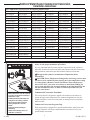
With this Commercial Conversion the temperature ranges
available through the thermostat control are as follows:
Available Thermostat Settings - Factory Configuration
11. Set the remote control to the desired operating
temperature, and restore the gas and water service to the
water heater.
F
85
100
102
104
106
108
110
112
114
116
118
120
C
29
38
39
40
41
42
43
44
46
47
48
49
Residential High
Temperature
Settings
12. Place/Stick Conversion Label to the front of the tankless
water heater and remove the Energy Star label. Leave the
new warranty certificate for the customer and discard the
original warranty certificate.
Commercial High
Temperature Settings
F
125
130
135
140
F
150
160
170
180*
185*
C
52
54
57
60
C
66
71
77
82*
85*
* Some models may be able to reach up to 180°F (82°C)
Commercial Conversion in a Multi-Unit Manifold
or EZ-Link™ Installation
Commercial Conversion in a Multi-Unit Manifold or EZ-Link™ Installation
Commercial Conversion of water heaters in a Multi-Unit
Manifold or EZ-Link™ Installation requires that each
tankless water heater in the installation gets a conversion chip
installed on the Control Board, as in steps 1 through 4. After
the chip installation the Program Chip Initiation is slightly
different from a single unit conversion since in a MultiUnit installation there is only one remote control. Complete
the entire manifold installation before continuing with the
Commercial Conversion procedure.
A. Complete the chip installation on each water heater as in
steps 1 through 4 on the front side of this document.
B. Find the two DIP switches located at the top right hand
side of the PCB. The switch labeled “DIP1” in the top
switch.
C. Change the DIP Switch #4 setting to the “ON” position.
DO NOT alter any other DIP Switch. The LED on the
PCB is flashing. At the same time, the display of the
Main Remote Control starts to flash.
D. Press the “Max” button located at the top right hand side
of the PCB for more than 1 second. The LED on the PCB
starts illuminating continuously. At the same time, the
display of the Main Remote Control is on continuously.
E. Change the DIP Switch #4 setting back to the “OFF”
position. DO NOT alter any other DIP Switch. The LED
on the PCB will stop illuminating. At the same time, the
display of the Main Remote Control will turn off.
F. Turn on the water heater at the remote control by pressing
the power button, see figure 3.
G. Press the UP arrow temperature adjustment button
several times to increase the temperature to a maximum
of 185*, see figure 4. This will verify the system has
been successfully converted. If the temperature does
not increase past 120 or 140, then the conversion failed,
restart the procedure at step A.
H. Set the remote control to the desired operating
temperature, and restore the gas and water service to the
manifold system.
I. Place/Stick Conversion Label to the front of the tankless
water heater and remove the Energy Star label. Leave the
new warranty certificate for the customer and discard the
original warranty certificate.
3