1
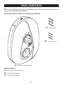
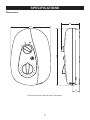
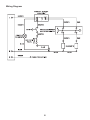
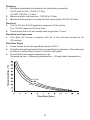
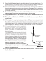
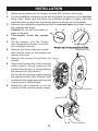
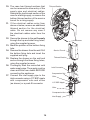
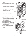
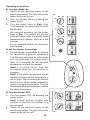
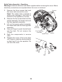
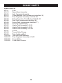
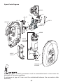
Vi e ira M Mira Vie Electric Shower Installation and User Guide These instructions are to be left with the user Contents Introduction.............................................................................................. 3 Patents and Design Registration........................................................... 3 Important Safety Information.................................................................. 4 Warning!................................................................................................ 4 Caution!................................................................................................. 5 Pack Contents.......................................................................................... 6 Mira Vie 8.5 kW, 9.5 kW or 10.8 kW Electric Shower............................ 6 Specifications........................................................................................... 7 Dimensions............................................................................................ 7 Wiring Diagram...................................................................................... 8 Plumbing............................................................................................... 9 Electrical................................................................................................ 9 Standards and Approvals...................................................................... 9 Flow Rate Graph................................................................................... 9 Installation Requirements..................................................................... 10 Plumbing............................................................................................. 10 Electrical.............................................................................................. 12 Installation.............................................................................................. 13 Commissioning...................................................................................... 16 Operation................................................................................................ 17 Advice to Users................................................................................... 17 Operating Instructions......................................................................... 18 Fault Diagnosis....................................................................................... 19 Maintenance............................................................................................ 23 Cleaning.............................................................................................. 23 Cleaning the Inlet Filter....................................................................... 23 Relief Valve Assembly - Resetting....................................................... 24 Notes....................................................................................................... 25 Spare Parts............................................................................................. 26 Spare Parts List................................................................................... 26 Spare Parts Diagram........................................................................... 27 Customer Service................................................................................... 28 Introduction Thank you for purchasing a quality Mira Vie Electric Shower. To enjoy the full potential of your new shower, please take time to read this guide thoroughly, and keep it handy for future reference. Mira Vie electric showers have separate controls for power selection and for temperature/flow adjustment. A unique flow regulator stabilises any temperature changes caused by water pressure fluctuations, which can result from taps being turned on or off or toilets being flushed. Products covered by this guide: Mira Vie 8.5A 8.5 kW 240 V AC (7.8 kW 230 V AC) heater with push-button Start/Stop. Available in a white/chrome finish. Mira Vie 9.5A 9.5 kW 240 V AC (8.7 kW 230 V AC) heater with push-button Start/Stop. Available in a white/chrome finish. Mira Vie 10.8A 10.8 kW 240 V AC (9.92 kW 230 V AC) heater with push-button Start/Stop. Available in a white/chrome or satin chrome finish. Recommended Usage Domestic Light Commercial Heavy Commercial Healthcare Patents and Design Registration Patents GB: 2 237 860 Ireland: 64471 Design Registration 000165071 - 0013 000165071 - 0014 If you experience any difficulty with the installation or operation of your new shower control, then please refer to ‘Fault Diagnosis’, before contacting Mira Showers. Our telephone and fax numbers can be found on the back cover of this guide. Important Safety Information Warning! 1. Products manufactured by us are safe and risk-free, provided that they are installed, used and maintained in good working order, in accordance with our instructions and recommendations. 2. THIS APPLIANCE MUST BE EARTHED. 3. In accordance with ‘The Plugs and Sockets etc. (Safety) Regulations’ in force at the time of installation, this appliance is intended to be permanently connected to the fixed electrical wiring of the mains system. 4. DO NOT twist the individual cable cores of the live and neutral conductors, as this will prevent them from entering the terminal block. 5. Make sure that any pipework that could become frozen is properly insulated. 6. DO NOT operate this appliance if it is frozen. Allow the appliance to thaw before using. The shower unit must not be fitted where it may be exposed to freezing conditions. 7. DO NOT fit any form of outlet flow control as the outlet acts as a vent for the tank body. Only Mira Showers recommended outlet fittings should be used. 8. If water leaks from the pressure relief valve, maintenance will be required before the appliance can be safely used. 9. There are no user-serviceable components beneath the cover of the appliance. Only a competent tradesperson should remove the cover. 10. If any of the following conditions occur, isolate the electricity and water supplies and refer to To contact us, on the back page of this guide. • The cover is not correctly fitted and water has entered the appliance case • The case is damaged • The appliance begins to make an odd noise, smell or smoke • The appliance shows signs of a distinct change in performance, indicating a need for maintenance • The appliance is frozen 11. Isolate the electrical and water supply before removing the cover. 12. Mains connections are exposed when the cover is removed. 13. Refer to the wiring diagram before making any electrical connections. 14. Make sure all electrical connections are tight, to prevent overheating. 15. This product is not suitable for areas with very high humidity (i.e steam rooms). Please consult your installer. Caution! 1. Read all of these instructions and retain this guide for later use. 2. Pass on this guide in the event of change of ownership of the installation site. 3. Follow all warnings, cautions and instructions contained in this guide, and on or inside the appliance. 4. The electrical installation must comply with the “Requirements for Electrical Installations” (commonly referred to as the IEE Wiring Regulations), or any particular regulations and practices, specified by the local electricity supply company in force at the time of installation. The installation should be carried out by an electrician or contractor who is registered, or is a member of, an association such as: • National Inspection Council for Electrical Installation and Contracting (NICEIC), throughout the UK • The Electrical Contractors Association (ECA), England and Wales • The Electrical Contractors Association of Scotland (ECAS) 5. This is a high power unit; it is essential to contact your electricity supply company to make sure that the electricity supply is adequate for the purpose. 6. The plumbing installation must comply with the requirements of UK Water Regulations/Bye-laws (Scotland), Building Regulations or any particular regulations and practices, specified by the local water company or water undertakers. The installation should be carried out by a plumber or contractor who is registered, or is a member of, an association such as: • Institute of Plumbing (IOP), throughout the UK • National Association of Plumbing, Heating and Mechanical Services Contractors (NAPH & MSC), England and Wales • Scottish and Northern Ireland Plumbing Employers’ Federation (SNIPEF), Scotland and Northern Ireland 7. This appliance is not thermostatic and can produce scalding temperatures if not operated in accordance with the instructions given in this manual. 8. Anyone who may have difficulty understanding or operating the controls of any shower should be attended whilst showering. Particular consideration should be given to: • the young • the elderly • the infirm • the disabled • anyone who suffers from a medical condition that can result in temporary incapacity (e.g. epilepsy or blackouts) • anyone inexperienced in the correct operation of the controls 9. When this appliance has reached the end of its serviceable life, it should be disposed of in a safe manner, in accordance with current local authority recycling, or waste disposal policy. Pack Contents Tick the appropriate boxes to familiarise yourself with the part names and to confirm that the parts are included. Mira Vie 8.5 kW, 9.5 kW or 10.8 kW Electric Shower 1 x Mira Vie Electric Shower Documentation 1 x Installation and User Guide 1 x Installation Template 1 x Guarantee Brochure 3 x Wall Plugs 3 x Fixing Screws Specifications Dimensions 96 318 210 37 All dimensions are nominal and in millimetres. Wiring Diagram Plumbing 1. Minimum maintained inlet pressure for satisfactory operation: 8.5 kW and 9.5 kW: 70 kPa (0.7 bar). 10.8 kW: 100 kPa (1.0 bar). 2. Maximum static inlet pressure: 1000 kPa (10 bar). 3. Minimum static pressure to keep the flow valve closed: 50 kPa (0.5 bar). Electrical 1.The 8.5 kW and 9.5 kW appliance requires a 40 Amp fuse. The 10.8 kW requires a 45 Amp fuse. 2.The terminal block will not accept cable larger than 10 mm2. Standards and Approvals 1.This Mira Vie shower complies with all of the relevant directives for CE marking. Temperature Rise (°C) Flow Rate Graph 1. These curves are for the specified outputs at 240 V. 2. All appliance heating elements have a manufacturing tolerance. Flow rates may be above or below those shown on the flow rate graph. 3. The left-hand axis shows temperature rise. Temperature rise = (Showering temperature) - (Supply water temperature). 10.8 kW 9.5 kW 8.5 kW Flow Rate (l/min) Installation Requirements Plumbing 1.The Mira Vie 8.5 kW and 9.5 kW electric showers are designed to operate with a minimum maintained inlet pressure of 70 kPa (0.7 bar) up to a maximum static inlet pressure of 1000 kPa (10 bar). The Mira Vie 10.8 kW electric shower is designed to operate with a minimum maintained inlet pressure of 100 kPa (1.0 bar) up to a maximum static inlet pressure of 1000 kPa (10 bar). 2.The appliance is normally connected to the cold water mains-fed supply. However, the water supply can be taken from a cold water storage cistern, provided there is a minimum maintained inlet head of water of 7 metres for the 8.5 kW, 9.5 kW and 10 metres for the 10.8 kW (the vertical distance from the base of the cold water storage cistern to the shower fitting handset). To reduce pressure losses and fluctuations, the cistern-fed water supply must be independent from other supply draw-offs, and should avoid long horizontal pipe runs and use swept bends rather than 90° elbows. For further advice please refer to the back cover of this guide for Mira Vie Showers contact telephone and fax numbers. 3. The appliance is suitable for installation within the shower area. It is fitted with a pressure relief device and must be positioned over a water catchment area with the controls at a convenient height for the user. The shower fitting should be positioned so that it discharges down the centre line of the bath, or across the opening of a shower cubicle, and must be directed away from the appliance. 4. The appliance is fitted with an inlet connector assembly that is designed to accept plumbing supplies from the top or bottom. The water supply can be fed with 15 mm pipe or 10 mm microbore pipe, suitably adapted into the inlet connector assembly. If 10 mm microbore is used, then an allowance for increased pressure loss must be made to ensure that the minimum maintained inlet pressure is achieved. 5. Do not fit the appliance to the wall and tile up to the case. The appliance must be fitted onto a finished flat and even wall surface. Otherwise, difficulty may be encountered when fitting the cover, and subsequent operation of the unit could be impaired (small pillars moulded on to the back of the case allow air circulation). 6. Use only the inlet connector assembly supplied with the appliance. Do not use any other types of fitting. 7.Refrain from applying excessive force when making any connections. Always provide mechanical support when making the plumbing connections. 8.This appliance is not designed to be plumbed directly from the rear. For a rear‑entry supply, add an elbow to the supply pipe and connect it as a rising or falling supply. 10 9. Do not install the appliance in a position where it may become frozen. The shower unit must not be fitted where it may be exposed to freezing conditions. The shower unit must not be used if you suspect it may be frozen. 10. We recommend that a non-restrictive (free-flowing) isolating valve is fitted in the cold water supply pipe to allow the complete maintenance of the appliance. Do not use a valve with a loose washer plate (jumper) as this can lead to a build up of static pressure. 11. To avoid damage to the case when soldered fittings are used, pre-solder the pipework and fittings before connecting them to the inlet stub. 12. Supply pipework MUST be flushed to clear debris before connecting the appliance. 13. The appliance is fitted with a 1/2” BSP male outlet thread, to accept an Mira Vie shower hose. 14.When installed in very hard water areas (above 200 ppm temporary hardness) your installer may advise the installation of a water treatment device, to reduce the effects of limescale formation. Appliance malfunction due to excessive limescale formation is not covered by the manufacturer’s guarantee. Your local water company will be able to advise on the hardness of water in your area. 15.A hose retaining soap dish is supplied to prevent the handset from dropping below the spillover level of the bath or shower, which could lead to contamination from back‑siphonage. The supplied hose retaining soap dish should meet the majority of user requirements for shower installations with flexible outlet fittings. However, there will be occasions when the hose retaining soap dish will not provide a suitable solution. In these instances an outlet double checkvalve must be fitted. This will increase the required supply pressure typically by 10 kPa (0.1 bar). Double checkvalves, fitted in the inlet supply to the appliance, cause a pressure build-up, which could exceed the maximum static inlet pressure for the appliance. 16.Avoid layouts where the shower hose will be sharply kinked. This may reduce the life of the hose. 11 Electrical 1. In a domestic installation, the rating of the electricity supply company fuse and the consumer unit must be adequate for the additional demand. This is a high‑power appliance, and it is essential to contact your electricity supply company to ensure that the supply is adequate for the appliance. Voltage drop due to local heavy demand will reduce the performance of the shower. 2. The appliance must be earthed by connecting the supply-cable earth conductor to the earth terminal. Supplementary bonding: Within the bathroom or shower room, all accessible conductive parts of electrical equipment and extraneous conductive parts that are likely to introduce earth potential, must be electrically bonded to earth using a minimum cable size of 4.0 mm2 if the cable is not mechanically protected (2.5 mm2 if mechanically protected). 3.The minimum cable size (cross-sectional area) must conform to BS 7671. 4.To obtain full advantage of the power provided by this unit, use the shortest possible cable route from the consumer unit to the shower. 5. A 30 mA residual current device (RCD) should be fitted. This may be part of the consumer unit or a separate unit. 6.A separate, permanently connected supply must be taken from the consumer unit to the appliance through a double-pole switch, which has a minimum 3 mm contact separation. The switch can be a ceiling mounted pull-cord type within the shower room, or a wall mounted switch in an adjacent room. 7. DO NOT twist the individual cable cores of the live and neutral conductors, as this will prevent them from entering the terminal block. 8. DO NOT exert strain on the terminal block. 9. DO NOT turn-on the electrical supply until the plumbing has been completed. 12 Installation 1. Determine a position for the shower, at least 200 mm from the ceiling. 2. Put the installation template on the wall and mark the positions of the top two fixing holes. Make sure that there are sufficient lengths of supply pipe and electrical cable to reach the connection points as shown on the template. 3. Remove the installation template and drill the top and side fixing holes. Insert the supplied wall plugs. Caution! Do not drill into cables or pipes in the wall. 4. Thoroughly flush the supply pipe. 5. On the shower, turn the Power and Temperature Knobs to the full anti‑clockwise position. 6. Remove the three retaining screws Retaining Screw that hold the cover on the shower and remove the cover. 7.Remove the service tunnel from the Shower shower. 8. Determine the direction of the incoming water supply: falling (entering the shower from the top), or rising (entering the shower from the bottom). Do not use an incoming supply entering the shower directly from the back. Add an elbow to the supply pipe and connect it as a rising or falling supply. 9. Rotate the inlet connector to suit the direction of the incoming water supply. Retaining Screws Service Tunnel Inlet Connector 13 10. The case has thinned sections that can be removed to allow entry of the supply pipe and electrical cables. Remove the top thinned section of the case for a falling supply, or remove the bottom thinned section of the service tunnel for a rising supply. 11. If the electrical cables enter from above or below, remove an additional thinned section for the electrical cable. Do not remove any case if the electrical cables enter from the back. 12. Secure the shower to the wall loosely through the top and side fixing holes, using the supplied screws. 13. Mark the position of the bottom fixing hole. 14. Remove the shower from the wall. Drill the bottom fixing hole and insert the supplied wall plug. 15. Replace the shower on the wall and secure through the three fixing holes, using the supplied screws. 16. Thoroughly flush the mains-fed cold water supply pipe. The supply must be clean and free from debris BEFORE connecting the appliance. 17. Connect the inlet supply pipe to the inlet connector using a 1/2” BSP nipple with compression nuts and olives (as shown) or a push-fit connector. Thinned Section Screws Service Tunnel Thinned Section Inlet Connector Compression Nut Olive 1/2’’ BSP Nipple Olive Compression Nut Inlet Supply 14 18. Bring the electrical cables into the case. 19. Strip a short section of the electrical cables. 20. Fit an earth sleeve to the earth wire. 21.Loosen the screws in the terminal block and insert the bare wires into the clamps: L (Live) = Brown Wire E ( ) (Earth) = Green Sleeved Wire N (Neutral) = Blue Wire Note! Do not twist the cores of the wires or strain the cables to make them reach the terminal block. 22.Tighten the screws in the terminal block so that they securely clamp the bare wires. 23. If necessary, fit an earth bonding clamp to the supply pipe and make sure that the bonding complies with the relevant regulations in force at the time of installation. 24.Replace the service tunnel. 25.Replace the cover. If the cover does not fit easily, rotate the knobs slightly so that they fit onto the spindles. Do not force the cover. 26.Tighten the three retaining screws. 27. Install the shower fittings, refer to your Shower Fittings Installation and User Guide. Retaining Screw Shower Retaining Screws Service Tunnel 15 Commissioning Caution! If you are unsure how electric showers work, please read the Operation section before continuing. 1.Turn the shower OFF by pressing the power button. Make sure that the button is in the OFF position. 2.Turn the temperature knob fully anticlockwise to cold and the power knob to low. 3.Turn on the water supply fully at the isolating valve. Check that water is not leaking from the bottom of the case. 4. Switch on the electrical supply at the double pole switch. The light around the power button will turn on. 5.Turn the shower ON by pressing the power button. Check that water flows freely from the shower within a few seconds. If not, refer to the Maintenance section. The water from the handset should be at full force and at a cool temperature. 6.Turn the temperature knob slowly clockwise to hot. As the knob is rotated the flow will be reduced and the temperature will remain cool (this shows that the flow regulator assembly is operating correctly). 7.Turn the temperature knob back fully anticlockwise to cold. 8.Turn the power knob to Eco. The temperature of the water should rise slightly. Allow a few seconds for the warm water to reach the handset - this shows that the half power setting is operating correctly. 9.Turn the power knob to High. The temperature of the water will rise further - this shows that the full power setting is operating correctly. 10. Set the shower temperature by rotating the temperature knob as necessary. Turn the knob clockwise for warmer water and anticlockwise for cooler water. Allow approximately 10 seconds for the adjusted temperature to reach the handset. Note! It is normal for the flow rate to change when the temperature is changed. 11.When the required temperature is reached, press the power button (OFF position). Water will continue to flow from the handset for a few seconds, as water is purged from the tank. The shower is now set for future operation. 12. Switch off the power at the double pole switch. Note! It is normal for the shower to make a slight hissing sound during operation. High mains water pressure and high shower temperatures will affect the tone. 16 Operation Advice to Users Note! Read the Important Safety Information section first. Warning! The spray plate holes must be kept clear. Lack of regular spray plate cleaning will lead to poor performance and cause early failure of the appliance. Refer to the Shower Fittings User Guide for more information. 1. Electric showers work by taking in cold water and passing it over the heating elements contained in the tank inside the shower. 2.The showering temperature is adjusted by turning the temperature control knob, which varies the flow of cold water across the elements. The slower the rate of flow, the warmer the water, and vice versa. The holes in the spray plate of the shower handset should always be kept clean to maintain a consistent flow and stable shower temperatures. 3.The appliance is designed to stabilise temperature changes caused by water pressure fluctuations. These fluctuations can be caused by taps being turned ON/OFF, or toilets being flushed. Under such conditions, average shower temperatures will be held within a 6 °C range, provided that the minimum required pressure is maintained. 4. Seasonal changes in the temperature of the incoming cold water supply and/or fluctuations in mains electrical voltage will effect the temperature of the water. Adjust the temperature knob as necessary to compensate. 5.The shower requires a minimum pressure of 70 kPa (0.7 bar) to operate, (100 kPa (1 bar) is required for 10.8 kW). At pressures above 70 kPa (0.7 bar), the shower will minimise the temperature fluctuations caused when other drawoff points are used. If the flow rate drops below an acceptable level, the heating element inside the shower will turn off, resulting in a cold shower. 6. If the water temperature reaches an unsafe level, then the thermal switch will turn off the heating element inside the shower. The heating element will be turned back on when the water temperature drops. The thermal switch will cycle ON/OFF/ON unless the flow rate is increased and the temperature of the shower is reduced. This will result in a fluctuating shower temperature. 7.Check the shower temperature before entering the shower. The previous user may have selected a different temperature setting. 8. When the shower is first turned on, or the temperature setting is changed, there will be a slight delay before the water temperature changes. 17 Operating Instructions To turn the shower on 1. Switch on the electrical supply at the double pole switch. The light around the power button will turn on. 2.Turn the shower ON by pressing the power button. 3.Turn the power knob to High. Wait 15‑20 seconds for warm water to reach the handset. For electrical economy, set the power knob to Eco. This setting will provide sufficient power when the supply water temperature is warmer, such as in the summer. For an unheated shower, set the power knob to Low. To set the shower temperature 1. Set the shower temperature by rotating the temperature knob as necessary. Turn the knob clockwise for hotter water and anticlockwise for cooler water. Wait 10‑15 seconds for the adjusted temperature to reach the handset. Note! It is normal for the flow rate to change when the temperature is changed. Note! If the water temperature cycles between hot and cold, the temperature is set too high. This is causing the thermal switch to turn off the heating element to reduce the water temperature. Turn the temperature knob anticlockwise to reduce the water temperature. To turn the shower OFF 1.Turn the shower OFF by pressing the power button. Note! A small amount of water may continue to flow from the handset for a few moments. 2. Switch off the electrical supply at the double pole switch. The light around the power button will turn off. 18 Fault Diagnosis The troubleshooting information tabled below gives you details on probable causes and remedies should difficulties be encountered whilst the shower is in operation. Warning! There are no user serviceable components beneath the cover of the appliance. Only a competent tradesperson should remove the FRONT cover! Malfunction Cause Remedy Shower is too hot during the summer. The incoming water is warmer in the summer, so the shower power setting is too high. Turn the power knob to Eco and adjust the temperature knob until the desired temperature is reached. Shower is too hot. The handset sprayplate is blocked. Regularly clean the handset sprayplate. Turning the temperature knob does not affect the water temperature. The handset sprayplate is blocked. Remove and clean the handset sprayplate. If the fault persists, contact the shower installer. The water continues to flow when the double pole switch is turned off. Broken diaphragm. Contact your installer to replace the flow valve assembly. No water or very low The handset sprayplate is flow rate. blocked. Clean the handset sprayplate. The incoming water supply stop valves, or the appliance isolating valve, is closed. Open the stop/isolating valve completely. The hose or handset is blocked. Clear the blockage or replace the hose or handset. The power is off at the double pole switch. Switch on the power at the double pole switch. The fuse is blown or the MCB/RCD has been tripped, indicating a possible electrical fault. Renew the fuse or reset the MCB/ RCD. If the fault persists, contact the shower installer. 19 (continued) Malfunction No hot water from shower, with the knobs in any position. The temperature cycles between hot and cold. Cause Remedy Other water outlets are being used during showering, causing the water pressure to drop below the minimum required. Make sure the other water outlets, such as the washing machine or dishwasher, are not in use during showering. The water pressure is below the minimum required. Make sure that the incoming water supply stop and the isolating valve are completely open. If the fault persists, contact the shower installer. Failure of the pressure switch, the micro switch or the thermal switch. Contact installer to replace faulty parts. The temperature is set too Turn the temperature knob high. This is causing the anticlockwise to reduce the water thermal switch to turn off the temperature. heating element to reduce the water temperature. ALL OF THE FOLLOWING REMEDIES MUST ONLY BE PERFORMED BY A COMPETENT TRADESPERSON! No hot water from shower, with the knobs in any position. Insufficient water supply pressure. Contact the local water authority. Failure of the pressure switch, microswitch or thermal switch. Check the continuity of the switches, using a suitable continuity measuring device. Replace the switches as necessary. An internal wiring connection has failed. Check the integrity of the internal wiring. One of the heater tank elements has failed. Replace the heater tank. Switch assembly diaphragm Replace switch assembly. fault, water dripping from the unit. The shower temperature cycles between hot and cold. The temperature is set too high. This is causing the thermal switch to turn off the heating element to reduce the water temperature. Turn the temperature knob anticlockwise to reduce the water temperature. DO NOT TAMPER with the thermal switch. (continued) 20 Malfunction Turning the temperature knob does not affect the water temperature. Cause Remedy The flow regulator is faulty. Replace the flow regulator. The handset sprayplate is blocked. Remove and clean the handset sprayplate. Refer to the shower fittings User Guide. If the fault persists, contact Customer Services. No water or very low The handset sprayplate is flow rate. blocked. Regularly clean the handset sprayplate. The incoming water supply stop valves, or the appliance isolating valve, is closed. Open the stop/isolating valve completely. The hose or handset is blocked. Clear the blockage or replace the hose or handset. Insufficient water supply pressure. Contact the local water authority. The heater tank is excessively scaled. Replace the heater tank. The pilot valve is faulty. Replace the flow regulator assembly. The inlet filter is blocked. Clean the inlet filter. Refer to Maintenance: Cleaning the Inlet Filter section. The power is not turned on at the double pole switch. Switch on the power at the double pole switch. The fuse is blown or the MCB/RCD has been tripped, indicating a possible electrical fault; for example, heater tank element failure. Renew the fuse or reset the MCB/ RCD. If the fault persists, contact Customer Services. Replace the heater tank. 21 (continued) Malfunction Cause Water leaks from the bottom of the case near the outlet, and there is no flow from the handset. The pressure relief valve in the tank has been triggered, (the shower has a pressure relief valve assembly that works to reduce the damage if the outlet is blocked or the unit is frozen). When the relief valve operates a small rubber ball is ejected. Remedy The water cannot be The pilot valve is faulty. turned off. Broken diaphragm. The supply pressure is below the minimum requirement. 22 Resolve the blocked outlet, and replace the tank assembly. Reset the relief valve assembly, refer to Maintenance “Relief Valve Setting” If the fault persists, contact Customer Services. Replace the flow regulator assembly. Replace the flow regulator assembly. Contact the local water authority. Check the static water pressure. Note that the static pressure may fall below minimum requirement when other appliances are drawing water, for example the dishwasher or washing machine. Maintenance Any maintenance must be carried out by a qualified tradesperson, following the instructions provided. Before replacing any parts, make sure that the underlying cause of the malfunction has been resolved. Warning! There are no user-serviceable components beneath the cover of the appliance. Only a competent tradesperson should remove the cover. Cleaning Many household and industrial cleaners contain abrasive and chemical substances that can damage the finish of your shower. Only clean the shower and fittings with a mild washing-up detergent or soap solution, and then wipe them dry with a soft cloth. Handset Poor shower performance can be avoided by regular cleaning of the handset. Use your thumb or soft cloth to wipe the rubber nozzles. The handset must also be descaled regularly. Cleaning the Inlet Filter Warning! Isolate the electrical and water supplies before removing the cover. 1.Remove the three retaining screws that hold the cover on the shower and remove the cover. 2.Remove the service tunnel from the shower. 3. Use a suitable spanner to remove the inlet filter from the inlet connector assembly. Hold a wrench across the flats of the inlet connector assembly to prevent damage to the connector, whilst removing the strainer. Do not remove the ‘O’ seal. 4. Remove the inlet filter. 5. Clean the inlet filter with a stiff brush. If necessary, use a kettle descalent in accordance with the manufacturer’s instructions. 6.Refit the components in reverse order. Screw Cover Inlet Filter Inlet Connector Assembly 23 Relief Valve Assembly - Resetting Warning! Isolate the electrical and water supplies before removing the cover. Mains electricity connections are exposed when the cover is removed. 1.Remove the three screws that hold the cover and remove the cover. Note! The rubber ball is ejected to reduce any damage if the outlet is blocked or the appliance is frozen. 2. Remove the five screws that hold the switch assembly, the heater tank and the flow regulator assembly. 3.Lift out the power switch assembly, the heater tank and the flow regulator assembly. 4. Use your finger to push the ball back into the tank. Do not remove the ‘O’ seal. 5.Refit the components in reverse order. 6.Replace the cover. If the cover does not fit easily, rotate the knobs slightly so that they fit into the spindles. Do not force the cover. Screws Switch Assembly Flow Regulator Assembly Heater Tank Ball 24 Screws Notes 25 Spare Parts Spare Parts List 406.27 Filter 439.74 Spare Neon Assembly 439.75 Inlet Connector Assembly 439.76 Clamp Bracket Pack (components identified ‘A’) 439.78 Flow Regulator Assembly, 9.5/10.8 kW 439.80 Switch Assembly, Push Button 9.5/10.8 kW 439.88 Seal Pack (components identified ‘B’) 439.89 Screw Pack (components identified ‘C’) 439.90Thermal Trip Assembly 439.92Heater Tank Assembly 8.5 kW 439.93Heater Tank Assembly 9.5 kW 439.94Heater Tank Assembly 10.8 kW 439.97Tunnel 439.98Tunnel Satin Chrome 439.99Tank Outlet and Ball 1539.349Terminal Block Assembly 1539.379 Flow Regulator Assembly, 8.5 kW 1539.400Cover White 1539.406Cover Satin Chrome 26 Spare Parts Diagram 439.80 A B 406.27 C 439.75 1539.349 A 439.74 1539.379 439.78 C B 439.90 439.92 439.93 439.94 439.97 439.98 B C 439.99 1539.400 1539.406 Important Note! Push-fit connectors must be assembled back to back onto the terminals of the micro-switches. A minimum air gap of 4 mm must be maintained between the connectors after assembly. 27 Customer Service Guarantee of Quality Mira Showers guarantee your product against any defect in materials or workmanship for the period shown in the Guarantee Registration Document included with your shower. Alternatively, to confirm the applicable guarantee period please contact Customer Services. To validate the guarantee, please return your completed registration card. Within the guarantee period we will resolve defects, free of charge, by repairing or replacing parts or modules as we may choose. To be free of charge, service work must only be undertaken by Mira Showers or our approved agents. Service under this guarantee does not affect the expiry date. The guarantee on any exchanged parts or product ends when the normal product guarantee period expires. Not covered by this guarantee: Damage or defects arising from incorrect installation, improper use or lack of maintenance, including build-up of limescale. Damage or defects if the product is taken apart, repaired or modified by any persons not authorised by Mira Showers or our approved agents. This guarantee is in addition to your statutory and other legal rights. What to do if something goes wrong If when you first use your shower, it doesn’t function correctly, first contact your installer to check that installation and commissioning are satisfactory and in accordance with the instructions in this manual. We are on hand to offer you or your installer any advice you may need. Should this not resolve the difficulty, simply contact our Customer Services Team who will give every assistance and, if necessary, arrange for our service engineer to visit. If the performance of your shower declines, consult this manual to see whether simple home maintenance is required. Please call our Customer Services Team to talk the difficulty through, request a service under guarantee if applicable, or take advantage of our comprehensive After-Sales service. As part of our quality and training programme calls may be recorded or monitored. Our Customer Services Team is comprehensively trained to provide every assistance you may need: help and advice, spare parts or a service visit. Spare Parts We maintain an extensive stock of spares and aim to provide support throughout the product’s expected life. Spares can be purchased from approved stockists or merchants (locations on request) or direct from Customer Services. Spares direct will normally be despatched within two working days. Payment can be made by Visa or MasterCard at the time of ordering. Should payment by cheque be preferred, a pro-forma invoice will be sent. All spares are guaranteed for 12 months from date of purchase. Spares that have been supplied directly form us can be returned within one month from date of purchase, providing that they are in good order and the packaging is unopened. Note! Returned spares will be subject to a 15% restocking charge and authorisation must be obtained before return. Please contact our Customer Services Team. Note! In the interests of safety, spares requiring exposure to mains voltages can only be sent to competent persons. Service Our Service Force is available to provide a quality service at a reasonable cost. You will have the assurance of a Mira trained engineer/agent, genuine Mira spare parts and a 12 month guarantee on the repair. Payment should be made directly to the engineer/agent using Visa, MasterCard or a cheque supported by a banker’s card. To Contact Us England, Scotland, Wales and Northern Ireland Mira Showers Customer Services Telephone: 0870 241 0888, Mon to Fri 8:00 am - 5:30 pm Sat 8:30 am - 3:30 pm E-mail: [email protected] Fax: 01242 282595 By Post: Cromwell Road, Cheltenham, Gloucestershire, GL52 5EP Eire Modern Plant Ltd (Dublin) Telephone: 01 459 1344, Mon to Fri 9:00 am - 5:00 pm E-mail: [email protected] Fax: Dublin 01 459 2329 Post: Otter House, Naas Road, Clondalkin, Dublin 22 Modern Plant (Cork) Telephone: 021 496 8755, Mon to Fri 9:00 am - 5:00 pm E-mail: [email protected] Fax: 021 496 8607 Post: Tramore Road, Cork Mira is a registered trade mark of Kohler Mira Limited. The company reserves the right to alter product specifications without notice. www.mirashowers.com 5+!3 1088848-W2-A (J06A-D) 28 © Kohler Mira Limited, October 2007